
cosmosuave
-
Posts
259 -
Joined
-
Last visited
Content Type
Profiles
Forums
Blogs
Gallery
Everything posted by cosmosuave
-
Thanks Wilba I'll test them with it out an post the results...
-
Looking for some help regarding the interconnection test... Here is the scenario... A few days ago I try'd the test with the IC's in only to discover that the test voltages with the IC's removed were too low... I rebuilt my PSU and get the correct test voltages on the IC's 5v and 12v... Installed the IC's performed the interconnection test using MidiOx and form pins A0 to A3 I am getting around 4.45v which I'm sure is fine... Pins A4 to Pin CS# are all 0v... Is it possible that I have ruined my SID chips? They are warm to the touch but not hot that they will burn your finger is this normal?
-
Ooops I'm using Smash's SID R3A board and I did notice that both pins go into the AC side of the rectifier so I guess it does not matter... Thanks...
-
Which pins are Vd and Vs on the J1 connection of the SID core PCB? I am wiring up the 14+ line and am not sure which pin of J1... If you know please use the J1 label as a reference... Thanks...
-
Not sure what steps to proceed with next on my stereo sid "sidated"... So far this is what's completed... 1. Core module loaded with latest mios V1.9 f 2. Sid modules complete x 2 3. 2x40 LCD is working 4. Optimized PSU complete and working 5. DINx4 module completed 6. All the surface controls are completed but not connected to the DIN module I want to test each sid module for the test tone before installing in the enclosure... I have looked at the optimised PSU pdf wiring diagram for V2 till my eyes water and am trying to figure out how to connect it all with plugin connectors instead of soldering individual wires... Are there any pics to help on this? Basically all my hardware is built and completed and now I need to connect it all... I have gone through the documentation but am unsure where is the best place to start? Appreciate anyone's suggestions... Thanks... Brian.
-
PwrSupply: Rectifier Substitution B40C800 for DB104
cosmosuave replied to cosmosuave's topic in MIDIbox SID
I took the pin out config in consideration of the DB104... here is the following Voltage readings that I get... 5.11 V between grd (- side of 100nf cap) and pos (+ side of 100nf cap) 7.96 V between grd (- side of 100nf cap) and 220 ohm resistor (for led connection) 1.12 V between grd (- side of 100nf cap) and pin#3 7809 regulator 13.12 V between pin #1 and pin #2 of the 7809.... Not sure why that is but can I assume to tap off of that connection for my 14 V feed? C64 PS outputting 5.11 VDC and 9.8 VAC which is correct... Thanks for the previous replies... In the meantime I'm going to check my connections and the voltage output of the C64 power supply that I have... -
Can I substitute a DB104 rectifier for the B40C800? Reason I ask is that my source did not have any and said the DB104 should work... Below are the links to the spec sheets... Forgive me I am not so knowledgeable on these compnents... DB104 http://www.ortodoxism.ro/datasheets/RECTRON/DB104.pdf B40C800 http://www.ortodoxism.ro/datasheets/wte/B40C800.pdf Thanks...
-
Hey Smash you were correct about the cap being backwards... I have since replaced it when it blew... Gotta learn the hardway... After several failed attempts with 2x20 lcd I was successful with a 2x40 only issue is that it is non-illuminated... I am eager to get this done after hearing some recent sound bites... I need to make a trip to the electronics store soon to finish the power supply and grab some ribbon cable for all the connections... Thanks for the pic compliments... A curved piece of white paper does wonders...
-
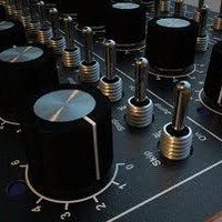
I thought I would update my SIDated project since I have had to park it for awhile... Below is what the front panel will look like when done... What is the best way to mount the PCB's? JB weld and some 8x32 machine screws? I may recess the encoder knob below the control surface...
-
Kitsune that's great.... I love the stuff that has been released on that label...
-
Not much digital experience... By the sounds of things my money for a course could be spent better elesewhere...
-
Since I have started building my SIDbox I though it would be a good idea to take some course at the local college to learn programming of micro controllers... Not being familiar with them would this be an asset for me in building any of the MIDIbox platforms? Through my work I can get reimbursed for successful completion of the course up to $1500 worth... I do have some previous electronics experience but nothing involving PICS and stuff... Below are the cousre outlines... Any thoughts? 7336 certificate name: COMPUTER ENGINEERING MICROCONTROLLER TECHNOLOGY description: All new electrical and electronic equipment is controlled by microcontrollers. If you are interested in learning everything about microcontrollers, this program is for you. The courses were designed and approved through the same process as the day time courses and qualify for the credit transfer to the full-time electronics and computer engineering technology diploma programs. Please take each course in the sequence shown below. admission requirements: Computer Engineering Fundamentals Certificate of Achievement or permission of the dept. notes: Laboratory Kits are NOT included in the price of courses. They may be purchased in the college bookstore or from outside sources. course code: CEEL-222 course name: MICROCONTROLLERS 2 category: Engineering Technology & Applied Science description: This is the extension of the CEEL-202 Microcontrollers 1 course. Examine the advanced features of the MC68HC11 architecture: I/O interfacing, interrupt processing, real clock timer, and A/D converter. The special interface board connected to the microcontroller system will be used in the laboratory, which will enable you to gain valuable practical experience. Special Requirement: Laboratory Kit (not included in the price of the course; may be purchased in the college bookstore or from outside sources) (includes materials fee - text extra)
-
Wow I listened to this at work yesterday on some shitty PC speakers and then just listened to it in my studio and I can't beleive how warm and rich that sounds... Is that straight out of the SID or is there some FX added?
-
Are those LED's on the encoders standard or did you add them on and how?
-
Thanks AM... I guess I am going about it the right way cos I did start with the IC and I have been using the component legs for jumpers... Good job on your SIDbox...
-
Thanks... SO....
-
Looking for some help or some links on how to make a perf board from a schematic drawing? I have no problems with PCB's but I have never done anything with perf board and what I want to add to my SIDbox is a this headphone buffer amp... http://www.paia.com/proddetail.asp?prod=9605K I have purchased the parts I just not sure the right way to go about this?
-
I connected D4-D7 to the corresponding pins on the LCD...
-
YESSSSSSSSSSSSSSSSSSSSSSSSSSS!!!! It works!!! I connected D4-D7 and I get the following... MIOS 1.9 TOM KLOSE READY Now to make a proper cable... Thanks for all your input... Seriously I was losing sleep over this besides the fact my 5 month old son has been keeping me up as well...
-
+1 for the MIOS... I'll be shits n giggles if the LCD works when I wire up DB4- DB7... Will try tomorrow... Thank you...
-
I have uploaded MIOS to my pre prog'd PIC18F4685 via midi and get the following output... I assume this is correct? Starting upload of mios_v1_9f_pic18f4685.hex Hex file contains code in MIOS range, forcing reboot! Received error code 01: Less bytes than expected have been received This was an expected error - please ignore!<------------------------------Is this normal? Received Upload Request Sending block 00000400-000004FF Received Checksum: 0E - OK Sending block 00000500-000005FF Received Checksum: 6E - OK Sending block 00000600-000006FF Received Checksum: 6D - OK Sending block 00000700-000007FF Received Checksum: 19 - OK Sending block 00000800-000008FF Received Checksum: 4E - OK Sending block 00000900-000009FF Received Checksum: 76 - OK Sending block 00000A00-00000AFF Received Checksum: 07 - OK Sending block 00000B00-00000BFF Received Checksum: 79 - OK Sending block 00000C00-00000CFF Received Checksum: 0E - OK Sending block 00000D00-00000DFF Received Checksum: 21 - OK Sending block 00000E00-00000EFF Received Checksum: 77 - OK Sending block 00000F00-00000FFF Received Checksum: 2C - OK Sending block 00001000-000010FF Received Checksum: 51 - OK Sending block 00001100-000011FF Received Checksum: 4F - OK Sending block 00001200-000012FF Received Checksum: 00 - OK Sending block 00001300-000013FF Received Checksum: 5A - OK Sending block 00001400-000014FF Received Checksum: 2C - OK Sending block 00001500-000015FF Received Checksum: 04 - OK Sending block 00001600-000016FF Received Checksum: 32 - OK Sending block 00001700-000017FF Received Checksum: 68 - OK Sending block 00001800-000018FF Received Checksum: 34 - OK Sending block 00001900-000019FF Received Checksum: 6B - OK Sending block 00001A00-00001AFF Received Checksum: 74 - OK Sending block 00001B00-00001BFF Received Checksum: 57 - OK Sending block 00001C00-00001CFF Received Checksum: 5A - OK Sending block 00001D00-00001DFF Received Checksum: 01 - OK Sending block 00001E00-00001EFF Received Checksum: 10 - OK Sending block 00001F00-00001FFF Received Checksum: 3A - OK Sending block 00002000-000020FF Received Checksum: 79 - OK Sending block 00002100-000021FF Received Checksum: 67 - OK Sending block 00002200-000022FF Received Checksum: 1A - OK Sending block 00002300-000023FF Received Checksum: 22 - OK Sending block 00002400-000024FF Received Checksum: 2D - OK Sending block 00002500-000025FF Received Checksum: 63 - OK Sending block 00002600-000026FF Received Checksum: 16 - OK Sending block 00002700-000027FF Received Checksum: 31 - OK Sending block 00002800-000028FF Received Checksum: 2C - OK Sending block 00002900-000029FF Received Checksum: 2A - OK Sending block 00002A00-00002AFF Received Checksum: 23 - OK Sending block 00002B00-00002BFF Received Checksum: 65 - OK Sending block 00002C00-00002CFF Received Checksum: 2D - OK Sending block 00002D00-00002DFF Received Checksum: 65 - OK Sending block 00002E00-00002EFF Received Checksum: 72 - OK Sending block 00002F00-00002FFF Received Checksum: 7E - OK Sending block 00003000-000030FF Received Checksum: 22 - OK Sending block 00003100-000031FF Received Checksum: 60 - OK Sending block 00003200-000032FF Received Checksum: 40 - OK Sending block 00003300-000033FF Received Checksum: 39 - OK Sending block 00007C00-00007CFF Received Checksum: 0E - OK Sending block 00007D00-00007DFF Received Checksum: 22 - OK Sending block 00007E00-00007EFF Received Checksum: 08 - OK Sending block 00007F00-00007FFF Received Checksum: 0B - OK Upload process complete Reason I ask is that I amstill having LCD issues... I have the contrast working on the LCD and have it wired for 4 bit operation but all I get is one line of bars... Maybe I have to connect the other leads for 8 bit? Latest LCD info this is the 3rd BTW... http://www.jameco.com/Jameco/Products/ProdDS/166983.pdf This LCD installation is stumping me and I have put enough hours in trying to figure it out is there not a plug in play solution?
-
Still having issues... Purchased a 16x2 LCD and have discovered that I need to get the contrast working in order to view anything... Currently I have tested the contrast control and only the 1/2 of the LCD is working which is the left half so the char readout is 8x2... I am testing the LCD on it's own not attached to the core... Setup for the contrast... Supply Voltage 9 volts... 25k pot Wiper connected to Vo (LCD) Pos connected to Vdd (LCD) Neg connected to Vss (LCD) The former LCD 2x24 I amanged to illuminate with the above method but now I think I burnt it out as one of the chips was too hot to touch... This is starting to get exspensive and frustrating... Some have mentioned to ground Vo but where do you ground it exactly? The outputs Vdd Vss Vo supply voltage but will not illuminate the LCD... What is the easy way to do this?
-
Yeah I saw the price afterwards..Ouch..
-
Check this out!!! http://www.e-sonic.com/whatsnew/weekly_NKK_SmartSwitch.htm
-
Still can't get the LCD to work... Just gonna buy another one... When I apply power to the core and then power off I'll get a blip on the LCD... Plus from the spec sheet I'll need 100V to power the back light... It was only $10...