cosmosuave
-
Posts
259 -
Joined
-
Last visited
Content Type
Profiles
Forums
Blogs
Gallery
Everything posted by cosmosuave
-
Thanks I figured IC6 but just wanted to verify and extra thanks for the schematic...
-
I have planned to power my LPC Module with J2 5v from a mini ATX PS instead of USB... As mentioned below I cannot find IC3 on the board is it suppose to menan IC6 as this is 7805 voltage regulator... When I apply 5v to J2 the LCD's pulse off and on and work properly when supplied via USB (J17 jumper installed) Thanks... Brian For Jumper J2... When used as +5V input: for supplying the core from an external stabilized Power Supply Unit (PSU). The voltage regulator (IC3) doesn't need to be connected, also the rest of the voltage stabilization circuit between J1 and J2 (X1, C8, C9) can be left out. If the core module (and all connected modules to this branch) drains more than 100 mA, it's recommended to mount C8 directly to J2 (a small cable between the outer soldering pads of the left-out 7805 will do this)
-
I have soldered header pins in J1 J2 J3 J4 now upon looking at them I am worried I will not have clearance for the connectors to attach to them once the front panel is connected... Now I have try'd to desolder one row of pins and it is a bitch gonna stop now in hopes that they can stay as they are... I planned to remove them and solder them to the other side of the board... Thanks... bri.
-
Not to thread jack but do I need the DOUT module to drive the LED's that populate the control surface from SMASH TV? Hope not or that means i have to order one or make one on perf board...
-
As usual I jumped the gun... Turning the contrast pot helped... One LCD not showing characters... From toubleshooting it is not the LCD or port but I suspect the ribbon cable... On both LCD's with the good ribbon cable tested on each port I get the Midibox marquee scroll then Step 1 screen... Will have to check the suspect ribbon cable... Ribbon cable was not crimped properly... I think I crimped that end with the strain relief connector on...
-
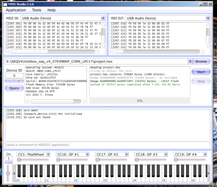
I have uploaded seq_v4_079 and it seems to have taken as there were no error read outs in MIOS but I am not seeing any characters on my LCD's even though they are lit up... Also all iI have connected is the core and the LCD's no SD card or control surface... Thanks... Brian
-
Found how to do it... Love the internet... http://www.wikihow.com/Convert-a-Computer-ATX-Power-Supply-to-a-Lab-Power-Supply Note that some power supplies may have either a gray or brown wire to represent "power good"/"power ok". (Most PSU's have a smaller orange wire that is used for sensing-- 3.3V- and this wire is usually paired at the connector to another orange wire. Make sure this wire is connected to the other orange wires, otherwise your lab power supply won't stay on.) This wire should be connected to either an orange wire (+3.3V) or a red wire (+5V) for the power supply to function. When in doubt, try the lower voltage first (+3.3V). If a power supply is non ATX or AT compliant, it may have its own color scheme. If yours looks different that the pictures shown here, make sure you reference the position of the wires attached to the AT/ATX connector rather than the colors.
-
Shit I just ordered one... Anyway I ordered a ATX mini one and I am gonna mod it as I don't see a need to have a fan on it anyway... Will have to make it work even if involes removing parts and placing on perf board...
-
Thanks for the suggestion Hawkeye but upon searching it looks like an ATX PSU will work as it has +/- 12v and 5v and 3v outputs... THe one I am looking at has a fan but I am sure I won't need it for my appliaction and will need to mod this to fit in a case of the sequencer... http://www.tigerdirect.ca/applications/SearchTools/item-details.asp?EdpNo=8533107&CatId=1078 Power Supply Specifications Form Factor ATX Wattage 400W Fan 120 mm Input Voltage 100 ~ 240 VAC +3.3V 22 A +5V 22 A +12V 1 18 A +12V Rails 1 -12V 0.5 A +5VSB 2.0 A
-
Hello... Looking for an all for one power supply for my SEQV4 and the issue is I require a 12v bi-polar PS for the AOUT NG module and at the same time the core requires 5v... I do not want to have to plug in 2 leads to supply the AOUT NG and supply core (powered USB hub as suggested)... I imagine I can tap off the bi-polar supply with a voltage regulator and some caps to get my 5v for the core... Who has done this and could they provide some insight? Thanks... This is the bi-polar supply I am looking to build... http://www.musicfromouterspace.com/analogsynth_new/WALLWARTSUPPLY/WALLWARTSUPPLY.php
-
Help - Installing the MIOS32 Bootloader SEQV4
cosmosuave replied to cosmosuave's topic in MIDIbox SEQ
Fixed and loaded... Problem was the USB cable... The whole time i had a cable under my nose in my headphone bag... Five min later everything fixed after 2 hours of frustration... -
Help - Installing the MIOS32 Bootloader SEQV4
cosmosuave replied to cosmosuave's topic in MIDIbox SEQ
Okay older version of IDE installed and all the menu options appear but after hitting the " "Program Flash" icon I get the following message... Connect to Emulator: No compatible emulators available. They may be disconnected, not powered, already in use or not compatible with this target. One thing I noticed using a USB port utility which shows USB ports connected, it does not show the LPCXpresso connected yet the led on the LPCX is blinking... Do I need drivers for the LPCXpresso? Okay I think it is the cable from my laptop to the LPCX as I borrowed it from someone and it is a multi dongled USB charging cable so me thinks it just supplies power and not data capabilities... -
Help - Installing the MIOS32 Bootloader SEQV4
cosmosuave replied to cosmosuave's topic in MIDIbox SEQ
Thanks!!! DL'g the older version... -
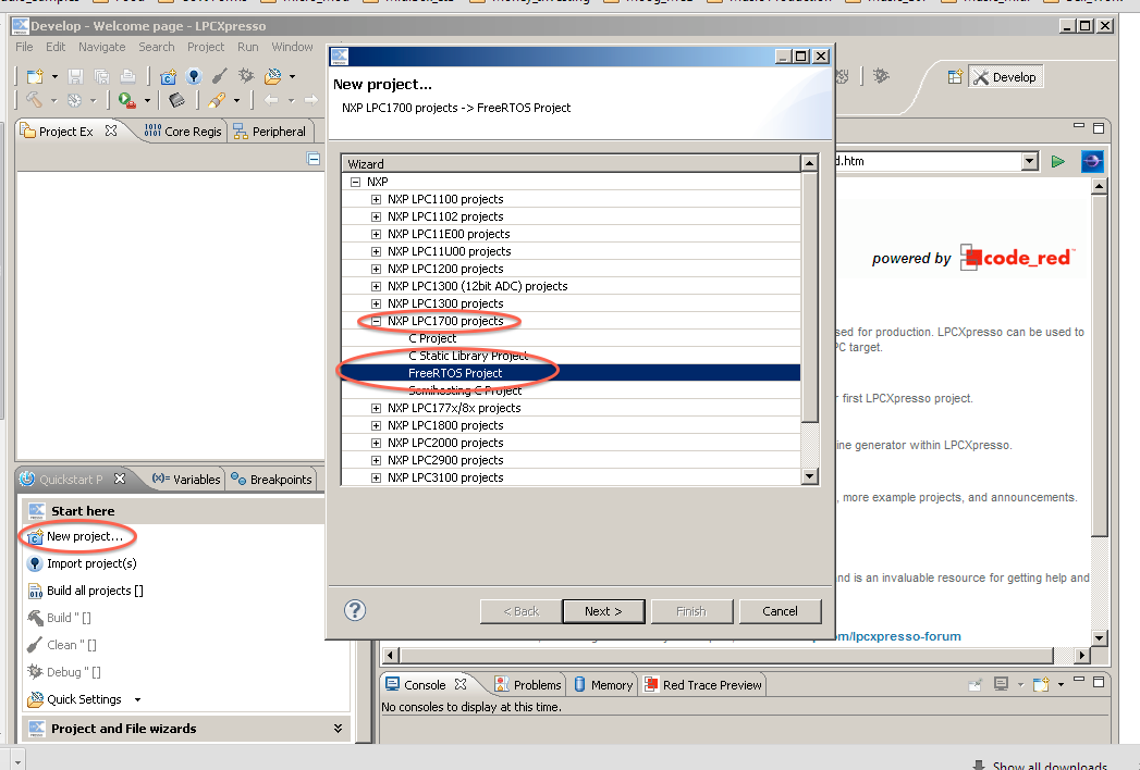
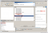
Hello... This is where I seem to struggle with the Midibox projects due to my lack of experience with micro-controllers and programming... My only other experience is with the stereoSID I built a few years back... I have all my boards made and now I am trying to install the MIOS32 bootloader on the LPC1769... Trouble is I am not seeing the FreeRTOS Project listed in the drop down for new project (see below as per the instructions)... Do I have DL this from the FreeRTOS site and import to the LPC developer program? Also I have DL'd the latest version of the LPCExpesso Developer Program... Thanks... bri
-
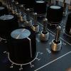
Got me knobs here in Toronto... Thanks Kristal...
-
I noticed you are using a Machinedrum... Are you using the MBseq to trigger the individual voices or having it play patterns?
-
Any particular reason you soldered to the underside of the main board for CV/Gate?
-
Looks good...
-
Thank you... I am financially not ready to go Eurorack as of yet...
-
Cool his vid at Tresor is great and i can't believe he is using an MMT-8 for sequencing... Will be on the look out for him if he play's Toronto... Your SEQV4 looks nice and i like how you put the jacks on the faceplate... I may do that or go from the rear nmot sure yet as it will be racked... Like the tune you guys did... Cool... Good to see people have gone the route with jacks... Since my Doepfer stuff is 1/8" I will go with that...
-
Any pics? Level shifter for gates what does that do? I am looking to CV/Gate 2 darkenergy's and a minitaur... On a side note... I just discovered Shawn Rudiman and he is from Pittsburgh like you, have you ever seen him play?
-
I have just started my build of the SEQV4 with analogue out (gate/cv) via DB25 connector... Has anyone opted out of the DB25 connector and substituted it for 1/8" jacks? I want to do this as I do not want to have to construct another interface to run my analogue gear or if you are using the DB25 how are you interfacing with your gear? Thanks... Brian
-
Right on...
-
Cool and thanks for putting this together...
-
How would one go about back lighting those knobs on the SEQV4?