Snoozr
-
Posts
146 -
Joined
-
Last visited
Content Type
Profiles
Forums
Blogs
Gallery
Everything posted by Snoozr
-
I'm looking for 10 white/black ones and 10 red/black ones. Feel free to PM w/ price. I'm in the US for shipping purposes.
-
There are some spots on the CS that allow you to screw that to the bottom of the case. You don't want the CS moving period because of all of the jacks attached to it. You can also screw the bottom of the case to the top of the case using the recessed holes in the bottom of the case.
-
Good news - for the next person, the encoders were due to the +5/GND cabling. And the Column 7 problem is now gone. Row 5 and Column 5 of the matrix are now blinking permanently. Found only a few posts regarding the matrix and none about blinking. It seems the logic thinks I have the corresponding buttons pressed and held down. I checked the diagrams to find out what pins correspond to these and then checked those connections between the CS and the surface. Connections seemed to be fine. Well if anyone has experienced this before, feel free to give me some tips. For now, I'm going to finally get my little guy back to play with. I'm super stoked as it's really clear with a full CS how incredibly deep the architecture is. From what I've explored so far, I'd say the MB-6582 easily hangs with fairly high-end synths. Glad I kept plugging away on this for so long. I started back in 2008 with some practice builds of Cores and Sid modules, all as a warm-up for this. It's been a journey of highs and lows for sure :thumbsup: Looking forward to the MB FM group buy as I'm hooked on Midiboxes.
-
MB6582: clones slave2 and resets on statup?
Snoozr replied to JRock's topic in Testing/Troubleshooting
I am having problems with my encoders (they all stopped working) so I thought I would switch around some of the ICs that are above Base JD1 and JD2 vi-a-vis. JD7 & JD8. Doing so caused this error message. Switching them back got rid of the problem. Maybe yours are switched? -
+1 but on a different part. Although mine was entirely decent :smile:
-
Sid Engine 2 LED is not dead - I was able to accidentally light it with the power disconnected (!) by touching its lead while touching J8 D6. The switch corresponding to Sid Engine 2 is also connected to J8 D6 and J5 D2 as its supposed to be. (Perhaps a transistor or capacitor is discharging?) I did not poke around for Column 7 as the usual inspections for shorts etc. did not turn anything up. Also Column 7 LEDs light up during the boot sequence so they are ok. It seems to be either the switch or the IC.
-
Come on everyone (Bump ba-dump)
-
So I have everything connected again but no encoders work (i.e., LCD shows no effect of encoders). I've established that rotating several "guinea pig" encoders is detectable on the Base in that the rotation alternately shorts/unshorts adjacent pins. So would this indicate that my U16 etc IC's are blown? There was a time when all encoders worked and the only thing that has really changed is the cabling. Also, Column 7 of the matrix does not respond to its button press and Sid 2 Select LEDs is either out or dead. Will poke around some more to see if I can nail this down some more. I had a problem with these two previously (see above) but it appeared at the time to be a cabling issue.
-
Sorted. Turning certain encoders alternately shorts/unshorts various pins.
-
First some updates that might be of interest to others. I was successful in re-attaching the pads with silver epoxy glue as described in a previous post. So if you have this problem, you might consider this as an avenue. Also, I used Chip-Quik for some desoldering. I was able to desolder at 2.25 on the temperature dial on a small Weller iron as opposed to the usual 3. Might be of interest to others if you have a tough desolder as I did (my CS board's connections are rather torched after several desolderings). And now for the question - I am again reattaching the stiff gray cabling from the CS to the base. Currently it's just on the CS. Cable 6 (looking from the top side of the CS) is shorted across all pads except 4. I've visually inspected and there are no obvious bridges. The guide indicates there should be no shorts/connections. My question is: would this possibly be due to some of the current values of the encoders, switches, etc.? Following the traces indicates that most (all?) of the traces go to various encoders. Or do I have some massive fault in the board due to all the soldering/desoldering?
-
OK - thanks. For the next person, there is electrically conductive epoxy at Mouser (below) that is good for repairing traces (and pads presumably). I may just clean up the pads and pad locations with isopropyl and reglue them. $25 is a bit rich but nothing's too good for my midibox :) http://mouser.com/ProductDetail/MG-Chemicals/8331-14G/?qs=sGAEpiMZZMtyU1cDF2RqUM5GB9DKDhl%2f%252bc9DWWHcI5c%3d
-
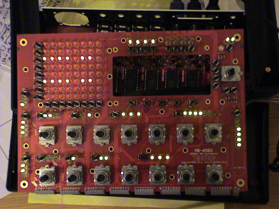
I am back at work on my MB6582 and in the course of desoldering, two pads came off. I recovered the pads. Although I doubt it, I was wondering if they are reattachable. They are on the bottom of the base board, i.e., in the above photo they are visible at right (specifically JD6 D01 and JD7 D03). The pads on the other side of the board are ok. I saw on another post that it is possible to attach wires in the event that pads come off. I wasn't sure how can I attach wires if the pads are off. Thanks.
-
I didn't describe things very well but a large number of the metal wires inside the cabling have sheared off due to metal fatigue (opening and closing the case has been bending them and they sheared off at the pads). So as a first step I was thinking these all need to be re-attached. I have at least 2 options I can think of: a.) desolder base pads, restrip wires, and then do a proper solder of wires to base, or b.) do a quick solder of currently broken wires, test everything for continuity as described, and then hot glue gun the wires so they cannot move/shear. Option A is preferable in a vacuum - however, I have already desoldered the base pads once for something else and they are in kind of rough shape already. I'm not very knowledgeable about how many desolderings a set of pads can take but if they can take a lot, Option A sounds viable. Also I have enough cable to make restripping viable as I misread the instructions and have 2 inches of cable instead of 42-43 mm. Option B sounds like the crap way but again if the pads go, then I'm even farther in the hole. Thoughts? Thanks for your help, Wilba. This is my first big DIY project ... and my first non-minor project problem, so I really appreciate the tips.
-
Alright, it's the cables for starters. They are an utter mess on the underside of the base. <demoralized> :sad:
-
(Picture did not come through 1st time)

-
“Likewise, you can test if the LEDs are working by first disconnecting all the 74HC595 and then applying ground to JD8 pin and 5V (through 220 ohm resistor!) to JD7 and JD6 pins. If that works, the LEDs are not dead, if it doesn't work, the problem is (probably) not on the base PCB side..†This test succeeds in lighting all LEDs. I seem to have HPF, BPF, and LPF filter in the reverse order of the schematic (verified twice) but a.) that’s the least of my worries, and b.) the filter selections worked fine before. Apparently I am not having a good weekend as I replaced two of the 595s in the wrong orientations, dimming the LCD and causing the 595s to get very hot very fast. These will obviously need to be replaced. Anyway, here is the picture after running the LED test hex file. Surprisingly there are some LEDs on after putting the 595s back in the right orientaiton. What’s become clear to me is that all of the opening and closing has put a lot of strain on the cabling. One portion of JD9’s cable has become separated. Moving the CS causes some LEDs to turn on and off, again consistent with certain bad connections (JD-D4 & D7; JD6 D1). I can’t visually see these bad connections except for the cabling one I mentioned so I don’t know if there’s stress fractures inside the PCB or what. (I had about 48 hrs where the little guy was working near flawlessly and now it’s a mess – huge sigh…)
-
Unfortunately while chasing down 2 minor problems I introduced more. Sid 2 button did not work, and Matrix column 7 button did not work. I traced connectivity of Matrix column 7 button to JD5 D6 on the main board. However, while doing this I saw some LEDs flash at a certain point -even though the power was disconnected-. Perhaps a capacitor discharged? One pin on Sid 2 button was not soldered so that looked like the culprit. I soldered Sid 2 button and all of the encoder tabs. Now when powering on, LEDs on Matrix Rows 1, 2, 4, 5, & 8 do not even flash (they had before). Matrix Rows and Columns 1, 2, 4, 5, & 8 are not selectable (button). There are also a number of other buttons and LEDs out. - - - After a nice round of cursing :smile: I checked for shorts. The Sid 2 button looks fine and there's no way to tell if there is a short under the encoders, although from the looks of the schematic there is nothing in the vicinity of the encoder tabs to short to. I tried permuting the 595s in U21-U23 - this did not change anything. It's not clear to me how I would test T2-T9. The LCD has not yet been mounted so that can be ruled out. <stumped>I will try looking at things again but I haven't much of a clue since just about all of this was working before</stumped>
-
Alright, think I got it now - R40-R55 must be inserted to get LEDs going. All's well that ends well. Although there's a few squirrely buttons and LEDs but that's a job for another day.
-
Also, nothing lights up when running the contents of mb6582_led_matrix_test2.zip. Updates: I had not soldered T2-T9 since they are listed as optional. However some searching reveals that Wilba says "They are not really optional". After soldering these, all buttons have effect on the LCD display save the following: Matrix Col 7 Matrix – all rows Sid Engine 2 Mode 2,3,4 Sid L/R It's possible I was not in the right menu for these buttons to have effects. Also, all LEDs are still off. LED test app also did not light them. Nebula indicates failure to solder T2-T9 may blow a shift register IC. Would that be an explanation for no LEDs? If so, which parts would these be - couldn't quite figure that one out.
-
So I thought I would start at square one. I can get +5V across JD9. So as a first test, I touched a resistor to +5V, touched the long leg of a spare LED to the resistor, and then the short leg to GND. The LED lights. So (I think) this confirms that my LEDs are short-leg=cathode like the MB-6582 CS construction guide indicates. I then tapped into current from JD9's counterpart on the CS. I routed current based on the above cathode description to the LED directly above JD9's counterpart (i.e., ramp waveform). Doing this caused the LED to light. Anyone have some thoughts on what I should check next? I'm getting power to the CS. FWIW all encoders work whereas no switches work.
-
Well, looks like I overlooked this "The ideal length to use when connecting the PCBs and using a PT-10 case is around 42mm-43mm between the holes/pads on each PCB". Looks like I've got some more desoldering in my future - yay. :thumbsup:
-
PS - it's the Mouser 25001-0802 cables. The 2-wire cable doesn't seem as stiff so maybe I will have to score the 8-wire cables to get them to bend more...
-
I got these and they seem too long. The case does not close easily. I tried folding them back over the Base PCB but the wire is so stiff that it will not bend easily. I don't want to desolder these because I already had to desolder the pads on the Base PCB once before due to misreading the instructions. Any tips anyone?
-
MB-6582 Troubleshooting (might need assistance)
Snoozr replied to frailn's topic in Testing/Troubleshooting
FWIW I had the same no output/Core problem a few weeks ago and did some posting about it in the SID forum. It was traced to a likely problem of blowing out the Core by touching the wrong pins on the SID socket. -
I managed to mess up 3 by connecting pins 8 and 28 as compared to 8 and 27. It was a slightly expensive way to find out my fine motor skills aren't what they used to be :whistle: