

Janis1279
-
Posts
287 -
Joined
-
Last visited
-
Days Won
1
Content Type
Profiles
Forums
Blogs
Gallery
Posts posted by Janis1279
-
-
Nope, didn't enable multiplexers. That would be part of my problem, but I can still test pots in unmuxed mode directly on the core without recompiling with this flag set, right? I want to make sure I'm wiring things up correctly before I add in the AIN module.
Are you corrected the some default values for pots in
the setup_midibox16e.asm file :
...
#define DEFAULT_NUMBER_AIN 0
;
; you could enable the multiplexers here to test this application
; with a MIDIbox64 based hardware
; if 0: no multiplexers (a *must* when MF module connected)
; if 1: use multiplexers
#define DEFAULT_ENABLE_AIN_MUX 0
...
in this string:
#define DEFAULT_NUMBER_AIN 0
edit your pots quantity from 0 up to 8 for unmuxed mode , recompile , and pots will work.
-
ITo do this I believe i need:
1X MIDIBOX64 core (MIDIBOX64E if Enc's were used)
1X AIN module
1X DIN module
1X DOUT module
1X LCD
1X USB GM5 Module
Is this correct?
So to make
7 pots
3 sliders
16 buttons
8 leds
1 screen
i would need all the modules above, is that right??
Yes ,but without the some Shift Register chips. You can read more in the Ucapps MB Hardware Platform section.
-
the first SR pin HEX numbers :
first 1 0 0×00 D0 / QA D7 / H
first 1 1 0×01 D1 / QB D6 / G
first 1 2 0×02 D2 / QC D5 / F
first 1 3 0×03 D3 / QD D4 / E
first 1 4 0×04 D4 / QE D3 / D
first 1 5 0×05 D5 / QF D2 / C
first 1 6 0×06 D6 / QG D1 / B
first 1 7 0×07 D7 / QH D0 / A
-
Can I replace the 6n138 by the 6n139?
From a Pic based Core article:
"Every MIDI device comes with such an optocoupler which isolates the MIDI Input from the device on the other side, just to avoid any damage.
For the case that you don't find a 6N138, you can also use a 6N139 (it's pin compatible)."
And the c3 1uF ceramic capacitor by one 1uF film capacitor?
Yes , it's a good replacement.
-
Are you corrected the some default values for pots in
the setup_midibox16e.asm file :
...
#define DEFAULT_NUMBER_AIN 0
;
; you could enable the multiplexers here to test this application
; with a MIDIbox64 based hardware
; if 0: no multiplexers (a *must* when MF module connected)
; if 1: use multiplexers
#define DEFAULT_ENABLE_AIN_MUX 0
...
-
:D
The chips and the pcboards arrived today !
Thank you , Thorsten ! ! !
-
-
You can read about programming voltage testing for Pic Burner in Uccaps too.
"+" probe to Pin 1 , MCLR
"-" probe to Pin12 or Pin31, GND , both pins are connected.
Regards, Janis
-
Hi
Read in some forums:
- better to use a 12V AC adapter instead of USB, or powered from other's computer's USB port,
- tWC= 8-10, tWP=30
There are many fuses for Pic Mcu's too
Be patient
Regards, Janis
-
You can made your own MB64 configuration in the setup_midibox64.asm file (open it in the Word Pad , easy to edit) .
Regards, Janis
-
I could be wrong, but for another MBHP projects may be similar data velocities
from the MIDIO128 design page :
"The software captures all 128 inputs within a period of 1 mS. If the status of an input pin has been changed, the program searches for the predefined MIDI event in a big table and sends it out"
-
for right soft choice :
-
-
B40C800 0,8A 100V from datasheet.
W04 to be better and can be used instead of B40C800.
-
midibox_lc_v1_6c\src\lc_io_table.inc
-
:D
Hi, Wilba,
Chips arrived . Thank you very much ! ! !
Regards, Janis
-
I found the pairs of leads on the power switch that are continuous. I don't understand why there are only two power switch symbols on the schematic. The datasheet doesn't help.
I think, you mean a double pole power switch. It's enough for switching on and off two separate secondary voltages as 5VDC and 9VAC simultaneously.
Regards ,
Janis
-
- I'm using the MIOS Studio midi keyboard controler, MIDI has DATA out but no audio on the PC.
- There´s only 5 pots in unmuxed mode(J5)
for the audio on the PC:
- In the Mios Studio > Options > Midi Device Routing >
You need connect left side Midi Device-Readable : Mios Studio Out Port with Midi Device-Writable : ..... ( in my computer it's Microsoft GS Wavetable SW Synth )
- For MB 64e is possible up to 8 pots in unmuxed mode(J5), editing in : setup_midibox16e.asm file
-
Is a plus sign is near pin 2 ?
Electrolytic capacitor value partly depends on which : external or internal 5 volts PSU will be used.
-
From the DOUT Module additional info section :
-
fuse link=topic=13944.msg119927#msg119927 date=1250801545]
As I planned to make my own PCBs including core/ain/din/dout inside, I'm finishing my kicad schematics and I'm a little bit stuck by the part that concerns J1 & J2 and all the power supply stuff at the bottom right on this schematic: http://www.ucapps.de/mbhp/mbhp_core_v3.pdf
if I plan to never use J1 (& and >5v psu) should I remove the rectifier, the uln etc ? should I put them however ?
If you now using yours 5V psu with J2 its quite so ,redraw a schem without the power supply stuff at the bottom right on this schematic: http://www.ucapps.de/mbhp/mbhp_core_v3.pdf
on a new maded pcb.
-
the midibox run with momentary type led buttons (push and keep push =ON , release =OFF)
or not "momentary" type (push =on , re-push =off) ?
???
In the midibox tutorials may be you read about a special feature which will be assigned to the buttons : Toggle value - Send learned value with the first keypress, send zero value with the second keypress.
-
Hi.
Mios suports your's Epson SED1278 chip LCD display.
You need compare are you soldering wires as in :
http://www.ucapps.de/mbhp/mbhp_lcd.pdf
In your case LCD pins are grouped in the odd and even columns, but pin meanings are the same as in a one row, I think.
Regards , Janis
-
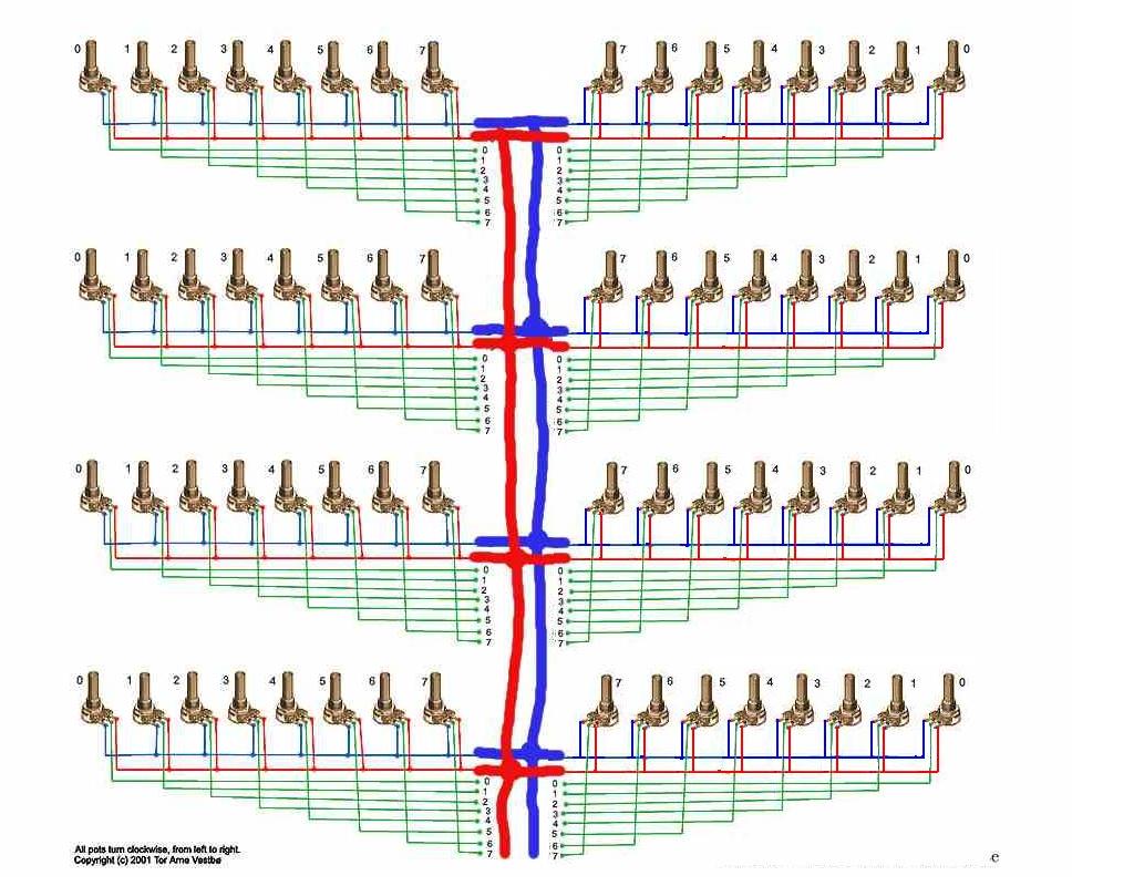
Yes, it's right. Only , when mirrored text, pots connections looks like reversed.
Redrawing some lines for better understanding.
Regards, Janis
Controlling Virtual DJ - New MIDIBOX - Help & Input Needed
in Design Concepts
Posted
The DOUT module comes with multiple serial registers 74HC595; every register provides 8 digital outputs, which are updated with the latch enable signal RCLK and shifted out with the clock signal SCLK. The advantage of using such shift registers is, that they can be cascaded to a long chain without the need of more than 5 cables to the core module. The DOUT board has been designed on a way which allows to cascade not only the ICs on the board, but also several DOUT modules.
The DIN module comes with multiple serial registers 74HC165; every register provides 8 digital inputs, which are sampled with the latch enable signal LD and shifted out with the clock signal CLK. The advantage of using such shift registers is, that they can be cascaded to a long chain without the need of more than 5 cables to the core module. The DIN board has been designed on a way which allows to cascade not only the ICs on the board, but also several DIN modules.