

Janis1279
-
Posts
287 -
Joined
-
Last visited
-
Days Won
1
Content Type
Profiles
Forums
Blogs
Gallery
Posts posted by Janis1279
-
-
Welcome, damiano,
Some infos about possibily button modes you can find in the MIDIbox64E Tutorial V2.x article under Midibox64E .You do not need to use the flip flop circuit to toggle the value .
May be you can draw the simple schematic diagram of what you wish to build ?
The basis of the midibox project is the Pic microcontroller based Core module (for the most of projects ). For the buttons and the encoders are used the DIN modules, for the leds ( ledrings ) - the DOUT modules. The potentiometers (> 8 pieces ) are connected to the AIN modules.
Regards,
Janis
-
Hi echo,
If you have these buttons or similar, you need read more carrefully the note-schematic on the last page ( page 4 ) of the current data sheet .
Regards,
Janis
-
As I understand your wishes, you need to change only DIN SR 3,1, to 5,0, (or to 5,1, or to 5,2, etc. ) The other : SR2 pins are DOUT pinsSo I am looking at the DIO_M_ROW_ENTRY
        ;; --> 1*DIN/4*DOUT <-- pins of the 4 row select buttons

        ;;       		DIN SR/Pin,  Row1 SR/Pin,  Row2 SR/Pin,  Row3 SR/Pin,  Row4 SR/Pin

        DIO_M_ROW_ENTRY  3, 1,        2, 2, 		2, 3, 		2, 4, 		2, 5
What do I need to change to define only the 4 pins on a new DIN SR. I would do DIN SR 5 PIN 0,1,2,3. Do I just delete The ;; --> 1*DIN/4*DOUT <-- Column and also delete the first entry which was labeled DIN SR/Pin like this?;; --> DIN <-- pins of the 4 row select buttons ;; Row1 SR/Pin, Row2 SR/Pin, Row3 SR/Pin, Row4 SR/Pin DIO_M_ROW_ENTRY 5, 0, 5, 1, 5, 2, 5, 3
Or do I add it to the first Din column below DIO_M_COL_ENTRY ?;; --> 1*DIN/4*DOUT <-- pins of the 4 row select buttons ;; DIN SR/Pin, Row1 SR/Pin, Row2 SR/Pin, Row3 SR/Pin, Row4 SR/Pin DIO_M_ROW_ENTRY 5, 0, 2, 2, 2, 3, 2, 4, 2, 5 -
as an example.
http://forum.hauptwe...&t=3777&start=0
and as here:
Filed under: Circuits — Greg Lipscomb ;

Here is a simple circuit that can be used to detect a black line in a DIY line following robot. The R1 and R2, need to be picked so that the current or voltage across the LEDs do not go over the specifications of the components. You can use the simple equation V=I*R. V=voltage accross the LED, it could be the 5 volt power source, I is the current through the component, and it can be measured with a multimeter. R is the resistor value. Anyway, the LEDs are infrared, and here are the numbers for them. The infrared Emitter Diode was a Kingbright L53F3C. The Infrared Phototransistor (detector) was a Kingbright L53P3C.
-
Hi ,
Paul
In my Midi Box Cores for LCD drivers I am using 2N2222 and 2N2222A transistors instead of BC337 without any problems.
Regards,
Janis
-
Every row button have a 1 NO contact.
-
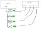
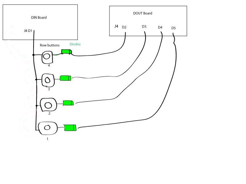
I have the buttons wired straight to the DIN J8 D1 and the diodes anodes (non-striped side) connected to these buttons also. The cathode (striped side) of each diode is wired to one of the DOUT J4 D5, D4, D3 and D2. Is this not correct? All the buttons do not work.
These connections are correct.
The better way to understand how the button matrix works, you need connect all 4x 6 buttons. Without leds, of course.
Should I rewire the diodes anode side (non-striped) to DIN J8 D1 and then put the button on the cathode side (stiped) of the diode? Then also put the DOUT J4 D5 on a button and so forth?
Why ?
Regards,
Janis
-
Do the diodes go before the buttons or after the buttons? These diodes are not on the DIN or DOUT board already right? The DIN diagram looks like the diodes go after the buttons then from the diodes cathode side (striped) to the DOUT connection. I tried this with the buttons before the diodes and I am thinking my only choice now is to try the diodes before the buttons. Maybe someone has a picture of what a working row button section looks like?
Thanks for your responses
The 4x row button diodes are additional diodes to DIN and DOUT diagrams.
The Led button module part is custom maded and a picture not give a more clearer view , anyway. But these 4 diodes are included in my module.
p.s. When I have interest to build or better understand for me any diagrams, schems etc. I am printing or drawing its,always. And then I look its many times if it needed .
Regards,
Janis
-
I do not have any leds wired yet. Another question I had was, do the leds need to be wired up for the row buttons to work? I am just trying to get the row buttons working. Where do the diodes go? the schematic of the DIN board shows diodes going in the middle between the row buttons and the DOUT J4 D2,D3,D4,D5. Or am I reading it wrong?
I may be wrong, but leds don't be wired for correct row buttons work.
diodes of the DIN board are connected : R1 to the green coloured wire R1on the DOUT board, R2 to the green coloured wire R2 on the DOUT board etc.
By default MB FM uses The third SR of DIN board for the row matrix buttons .
Regards,
Janis
-
Оу, ÑпаÑибо большое за ответ... но очень интереÑует Ñледующий вопроÑ.
Как Ñти Ñамые ÑенÑорные площадки подключать к ДИÐам ... напрÑмую или через дополнительную микруху какуюто... Ñ ÐºÐ°Ðº то видел доку на форуме но так и не нашел ее в поÑледнее времÑ
Na skoruju ruku poiskom nasjol:
no vozmozno, eto sovsem ne to.
Po podsojedinenijam raznih datcjikov k MB platforme pripominaju user: audiocommander
Udacji
-
ГоÑпода вÑем привет,
ПодÑобите Ñоветом а возможно и помощью.
Хочу Ñобрать на оÑнове мидибокÑа клавиатурку, да не проÑтую а Ñ Ð²Ñ‹Ð²ÐµÑ€Ñ‚Ð¾Ð¼.
Многим наверное не понÑÑ‚ÑŒ Ð¼ÐµÐ½Ñ , но... хочу миди-клавиатуру на 2,5 октавы Ð°Ð»Ñ EMS AKS, EDP WASP и иже...
то еÑÑ‚ÑŒ плоÑкую ÑенÑорную клаву и что б проÑто по ÑŽÑбу врубалаÑÑŒ в комп. обычных миди, Ñкрана, оÑобых наÑтроек и Ñ‚.д. Ñовершенно не нужно. Питание желательно ЮСБÑшное что бы было. Из бонуÑов к Ñамой клаве пару кнопок на тойже технологии Ð´Ð»Ñ Ñдвига ÑтроÑ, Ð°Ð»Ñ +/- октавы и пару Ñветодиодов Ð´Ð»Ñ Ð¾Ð±Ð¾Ð·Ð½Ð°Ñ‡ÐµÐ½Ð¸Ñ Ð¿Ð¾Ð»Ð¾Ð¶ÐµÐ½Ð¸Ñ.
Где то на мидибокÑах пару лет назад Ñ Ð²Ð¸Ð´ÐµÐ» топик Ñ Ð¾Ð¿Ð¸Ñание Ð¿Ð¾Ð´ÐºÐ»ÑŽÑ‡ÐµÐ½Ð¸Ñ Ñ‚Ð°ÐºÐ¸Ñ… площадок чуть ли не на прÑмую.
Может кто чего подÑкажет?
И правильно ли Ñ Ð¿Ð¾Ð½Ð¸Ð¼Ð°ÑŽ что мне нужны ÑобÑтно:
1Ñ… - Ñдро - ультра Ñдро наÑколько Ñ Ð¿Ð¾Ð½Ð¸Ð¼Ð°ÑŽ Ð´Ð»Ñ Ñ‚Ð°ÐºÐ¸Ñ… задач излишне
2Ñ… - Din -ÑобÑтвенно Ð´Ð»Ñ ÐºÐ½Ð¾Ð¿Ð¾Ðº (32 клавиши (2,5 октавы) + 2 Ð´Ð»Ñ Ð¿ÐµÑ€ÐµÐ¼ÐµÑ‰Ð°ÐµÐ½Ð¸Ñ Ð¿Ð¾ окатавам = 34 площадки)
1Ñ… - Dout - Ð´Ð»Ñ Ñветодиодов :)
Ð’Ð¾Ð¿Ñ€Ð¾Ñ Ñ‡Ñ‚Ð¾ нужно Ð´Ð»Ñ Ð®Ð¡Ð‘ и Ð¿Ð¸Ñ‚Ð°Ð½Ð¸Ñ Ð¾Ñ‚ него, как Ñто вÑе подрубить вмеÑте.
ОговорюÑÑŒ в ДИУ Ñ Ð½Ð¾Ð²Ð¸Ñ‡ÐµÐº откровенный. То еÑÑ‚ÑŒ модить аналог Ñто 1, Ñобрать ÐПЦ Ñто тоже 1, ну или чаÑÑ‚Ñми модульник паÑÑ‚ÑŒ... а вот Ñ Ñ†Ð¸Ñ„Ñ€Ð¾Ð¹ и ÑенÑорами у Ð¼ÐµÐ½Ñ ÐºÐ°Ðº то в -.
Заранее буду благодарен за помощь :)
Privet,
Toljko otnositeljno standartnogo MB zjeleza.
V kacjestve centraljnogo modulja na ; PIC18F452 proce, Core po umolcjaniju imejet MIDI IN, MIDI OUT .Sjuda mozjno podkljucjitj GM5 module i budet USB gnezdo dlja PC.
2x DINX4 dolzno bitj dostatocno, no jesli ponadobitsja na upravlenije boljse vhodov, vozmoznosti rassjiritj imejetsja
Dlja svetodiodov i odnoi 74HC595 mikruhoi budet dostatocjno.
s uvazenijem,
Janis
-
Zdravstvui.
A pazve priobresti GM5 mikruhu, platu ( jesli neobhodimo) i razsjiritj kolicestvo vhodov / vihodov mozjet okazatsja slozjneje cjem izobretatj
svoi kontroler ? Ja ne uveren.
http://www.midibox.org/dokuwiki/tk_gm5_bulkorder
s uvazenijem,
Janis
-
just to add to my previous question.
I am reading about diodes and see that electricity goes one way in them. It starts from the non striped side (anode) and goes to the striped side (cathode. So from understanding this now, should I connect the first row button to the anode side of the diode and connect the cathode side to the DOUT input or ...?
Hi echo
Not any or... !
But are your leds are connected with it's longer legs to the DOUTX4 J4:D1,D0 and J5:D7,D6,D5,D4 pins ( in each column 4 x leds with longer pins connected together ).
Regards,
Janis
-
Hi all!
Here's my version of the SID-Board.
It's based on two 8580, compatible to the Core32 board and the drivers found in the repository.
Chip select is on J5A, but can be anywhere else.
It only needs a +5V supply, the 9V are generated on board. Also there are output amplifiers
to attennuate the signals to a 1Vpp level, line-out compatible.
The board is 80x50mm, two layer.
I am currently doing a redesign with two 6581 and two 8580 SIDs. More details soon.
Questions, Ideas etc. are welcome.
Hi, luke
In the your MBHP_SID_V4.pdf file the 74HC595 SRs outs are connected to diferent pins of Sids, than I can saw in the Sid module and in the fnp-sid ( stereo sid ) schems. The first SR in this chain controls a data bus instead of addreses and the second SR controls a address bus instead of data.
Is that realy workable without any software changes?
sorry, may be I am wrong.
Regards,
Janis
-
Thanks for pointing that out, nILS. As stated earlier, I'm a total electronics n00b so I could use a little help here. How should I be measuring the 9V rail? To be clear, the fuse is in the C64, it's powered on, and I'm measuring across the fuse.
Here :
http://www.zimmers.net/anonftp/pub/cbm/schematics/computers/c64/250469-rev.A-right.gif
you can find the 9VAC input : 9VAC1 and 9VAC2 pins.
The 9VAC you can measure between 9VAC1 and a fuse F1 connection points.
From your earlier posts, looks your 9VAC supply is OK ( you got a right reading of 11.82V on a Sid socket pin 28) .
Regards,
Janis
-
cheers, bhc303
Today I got my 2 x Mos 6581 chips.
And both of its are look fine !
Thank you very much !
Best Regards,
Janis
-
hi folks,
I'm about to build a bigger VU-meter using the LM3915.
The IC has open collector outputs which can sink 30 mA max. I need 120mA per output.
first Idea: 4009 inverting buffers (with pullup reistors) and some ULN2803 (or 2804) driver ICs. But I guess, that's pretty hardcore.
second Idea: would a simple PNP-transistor per output work? Any Idea, which type would be suitable for 120mA@5V ?
thanks in advance.
I prefer a PNP-transistor type BD136 or similar
Regards,
Janis
-
Not to much of a bump here.
I am configuring my MBFM and I am having issues with the speed of the encoders. I have tried the different encoder modes Detented, Detented2,3,4,5 and have not had any luck finding the sweet spot. I also tried the absolute fast and slow settings described above. I have better results using detented2 and 3. I can turn the data encoder very slow to step up one but if i turn it a full click it jumps 4 spaces. Any suggestions. I understand there is a topic on this in German but i can't read German :( My link
I saw the encoder settings for the MBFM made by me :
#define CS_MENU_ENC_SPEED_VALUE 3
and by the type :
MIOS_ENC_MODE_DETENTED2 for all encoders
Regards,
Janis
-
In a setup_mbfm_v1.asm file you can find more info about encoder types and encoder's speeds
Can you upload some pics of your soldered OPL3 board both sides ?
Regards,
Janis
-
Yes 4.9v is very stable. Can I touch the ICs with my finger when they are turned on without frying them? There are obviosly still a few things I could learn about electronics. I currently am using a 9vAC 400ma to pwer the core. I have switched between the mbfm testone and mbfm hex a few times but I will try again.
I also have 2 out of 8 banksticks connected and they did auto format when MBFM hex was loaded. Is there any reason they are the problem? I also retried the jsynthlib editor and was able to make the mbfm audio cut out when changing parameters from jsynthlib but I did not hear any changes on the FM itself and the midi is sending correctly I believe.
How hot or warm is the +5v IC I do'not know, but to screw on it to a heatsink I want to recommend anyway. Your 9Vac 400mA power supply looks very good ! Another ICs in normal conditions are never be very hot.
Quantity of banksticks are more for future possibilities.
Could it be that my pic is only partially bad? Should I try with my 18F4620?
You can try with Pic18F4620 too, i am not sure your PIC18F452 is damaged.
In earlier post you wrote:
"I tried adjusting the volume for each instrument and operator to zero and I was still getting audio with no change in volume. "
Are your MBFM CS is working properly or i did not understand something? May be somewhere are connection mistakes ?
Regards,
Janis
-
The Pic18F452 is correct for MBFM.
I am thinking about 5v power supply part .
Is it stable 4,9v as echo wrote all the time and the +5v ic is not so hot ?
-
May be you can find some more usefull info in this :
topic
Regards,
Janis
-
From Wiki pages :
Can you connect multiple SIDs in parallel to one Core, to get a "unison" kind of sound?
Yes, this feature is available starting with the MIDIbox SID 2.0.
 Is this next piece still relevant?
 As TK says: you can connect multiple SID modules to one core module, in this case they always listen to the same control data. But the audible effect isn't really so interesting. If you are having two identical SIDs, then the volume will just be doubled (the oscillators are digital and therefore always output exactly the same waveform). This option can make sense if you want to switch between 6581 and 8580 because of the different filter characteristics. But for really interesting (especially fat) sounds, seperate cores are the best option, so that the SID parameters are modulated independent from each other. The result is much more analog-like(especially when the LFOs are in freerunning mode and the finetune/portamento/ENV parameters are slightly different).
Can we have more SIDs in one MB SID?
TK: As always I have to define such specs before beginning with the implementation. First I thought that controlling two SIDs from one control surface is sufficient for stereo effects. Then I was possibly in such a volatile temper that I decided the incredible: controlling 4 SIDs from a single PIC, which is doing the sound engine of one SID in parallel! Hard to believe that this works without affecting the realtime capabilities too much. I'm really proud that it works without trouble.
However, if you really want 8 SIDs, TK suggests: you could build two 4*SID systems… this will possibly cost you 50 EUR more, but what are 50 EUR compared to my unpayable sparetime

I'd go with that suggestion

-
I found this info :
Hint: it's possible to give each MIDI port it's own name by editing the [strings] section in the midibox.org_gm5.inf file.
Example:
WDM.MIDI_1.szPname="MIDIbox SID (1)"
WDM.MIDI_2.szPname="MIDIbox FM (2)"
WDM.MIDI_3.szPname="MIDIbox SEQ (3)"
WDM.MIDI_4.szPname="MIDIbox Stribe (4)"
WDM.MIDI_5.szPname="Keyboard (5)"
<P class=INFO>This helps you to organize your MIDI ports, so that they are easier to find:
use midi studio
in MIDIbox Tools & MIOS Studio
Posted
Hi, damiano,
the first step is to build the MIDIO128 interface,
the second step is to configure it with the MIDIO128 Tool.
or may be I am wrong. I have not any project with the MIDIO128 interface yet.
Regards,
Janis