philetaylor
-
Posts
828 -
Joined
-
Last visited
Content Type
Profiles
Forums
Blogs
Gallery
Everything posted by philetaylor
-
Yes with the CORE32, d0=lcd1, d1=lcd2 etc etc. Phil
-
You have a desk and lamp? I have a table, can't afford a lamp (spent all the money on the car :) )
-
Obviously I meant between collector and v+ :)
-
Just looking at your circuit, is there any reason why the load is wired between the emitter and ground? Usually you would place the load between collector and ground (with the emitter directly grounded). I have found a quite nice website that will help you with calculations etc: http://www.kpsec.freeuk.com/trancirc.htm Cheers Phil
-
I would try it without the capacitors, with 3 x 4700uF they will take quite a while to discharge which could be why you are seeing a slow switch-off. Also did you remove R4/R5 as with them in, there will always be some current flow through the base of the 2n3055 which could be why it never fully switches off. As to why it is never fully on, I would check the current through the lamp, for fully on it should be about 8A. Any less means that you may need an even smaller base resistor on the 2n3055. Cheers Phil
-
Sorry, you are quite right, with the N and P connections on the LCD connections, you should be fine with 1uF polarized electrolytics... Cheers Phil
-
Great. Another thing I did think, R3 will need to be reasonably big (about 2-3W) as it will have about 200mA across it.... Phil
-
Hi Ultra. Yes I limited the current to the backlight as per the datasheet, 56R IIRC. I always screw up anode/cathode connections on circuits (bit of a mental block I think) yes you are quite correct! The datasheet doesn't mention P/NP caps but the datasheet example uses NP and luckilly I had a never finished talkback project that used lots of 1uF NP so I stole them :) You may be able to use polarized but it could be a bit tricky working out which way round to put them. Maybe worth checking with TK to see what he used? Yes you are quire correct about the data line assignments. I moved away from the conventional D0=lcd1, D1=lcd2 because I am using an 18F4685 and D0-D3 are not available so I thought that I would start at D7 instead! AFAIK, the pinout for the CORE32 LCD is different to the CORE8 to make it more 1-1 for standard CLCD's so you may need to change it a bit... Cheers Phil
-
Also, assuming you are just using one BC547, I would lose R4/R5 completely. the emitter of the BC547 can just go straight to the base of the 2n3055 (via R3) and shouldn't need connecting to the 12v rail at all.
-
That's pretty much what I would expect. Ohms law states that I=V/R so with a 10K base resistor (R3), at 12V you should get about 1.2mA across R3. I don't know the spec of the 2n3055 but you need a collector current of about 8.3A so assuming it can handle a gain of about 40x you will need to replace R3 with something like 56R (you should then measure about 200mA across R3) but you might want to try some higher values and work down until it works! This also means that you will need to reduce R2 as well, probably about 4-500R should be OK. **WARNING** It is about 18 years since I did transistor theory so I may have got the above completely wrong :) Phil
-
I think if it was me, at this point I would fire up my oscilloscope and verify that data is reaching the pins of the display. I guess that you don't own a scope though? If you are absolutely certain that it is wired correctly then we are really looking at either faulty PIC I/O pins or a faulty display. Either is possible especially if (like I often do) you wired things wrong initially.... PIC's are incredibly robust but it is possible to kill inidividual pins. It may be worth investing in a cheap 16x2 CLCD display. These can be picked-up for a few euros and are easy to wire and are definately fullly supported by MIOS. If you are going to build any more Midibox projects in the future, i'm sure you will use it. I keep the first 16x2 display that I bought for just this reason. If I think I may have blown something, I plug it in to check if the PIC is still working :) Cheers Phil
-
Hi. I wouldn't worry about the 'snow'. This simply shows that the display has not been initialized properly. Usually when a GLCD first powers up, it's RAM contains random values, the last section of USER_LCD_Init will clear all display RAM. This does show that the display is either not talking to the PIC (wiring problem) or there is something wrong with the initialization sequence. I have done a quick comparison between what the MIOS driver should be sending and the recommended initialization sequence from the lcd-module.com website and they look pretty close. There are some differences but I don't know enough about the display to know if they are important! I will see if I can find any more info about this display (in English) and I will let you know. Phil
-
Hi, I have to agree with S1 that it's probably a wiring issue as the driver should at least display something even if it doesn't use the whole screen. I will happilly take a look at it for you but trust me, if you fix it yourself you will feel 'much' better :) One thing, can you let me know what exact model you have as looking at the datasheet, the different models have diffferent backlight current requirements, It mentions 2000mA at some point which looks very high to me and would cause the 7805 (regulator) to brownout which is why you are seeing errors as the PIC is constantly rebooting. You could try (very carefully) touching the 7805, if it is too hot to touch then this is the problem. (don't blame me if you burn yourself!). Also what type of power supply (voltage AC or DC) are you supplying the Core with? I tend to use 9V DC (as I have a lot of them). As you read German, you might be able to translate the section that deals with the backlights in the datasheet and let me know if I have misunderstood it as babelfish doesn't always do the best job!!! Thanks
-
This is because that code was not written for SDCC which I believe doesn't support the int16 datatype on PIC16's. To be honest you will spend more time trying to get that driver working than writing a new one. MIOS already contains a driver for the T6963C which is written in assembler NOT C (so will likely be quicker than a C version). The issue is the amount of processing that is needed as the driver must rotate the screen output by 90 degrees when displaying text. There is a non rotating driver which is quicker but the display must be used in a portrait orientation. Phil
-
Nice :) I have also written a driver for the DOG clcd using SPI, it seems quite a bit quicker than the parallel driver so do you think it is worth committing? If so what should I call it? dog_spi ? It would be useful if people wanted to use more than 2 of them. Cheers Phil
-
Brilliant. Did you have to change much to get the driver working?? EDIT: btw, what capacitors did you use???
-
lol. The only problem with this is there is no flux left in the solder once you reheat it so you may get a dry (or brittle) joint. I tend to agree with s1 here, wrap the wire round the pin and then solder. Phil
-
Hi. Looking at the datasheet for the YM1602C, it looks pretty standard. If you have a line of 'block' characters then this usually means that the display is receiving power but has not been initialized. This would indicate a wiring problem. The display supports both 8 and 4 bit but unless you are using a PIC18F4685 (which you say you aren't) then the default will be 8 bit. The LCD display type can also be selected by programming a different PIC ID, by default the ID is 0000000000000000 and unless you requested a different one (I take if you bought it from SmashTV or Mike) then the default is a character LCD. I know you have checked it but I would definately suspect a wiring problem, the fact that you are getting anything on the display means that it doesn't look like you have mirrored the connections :) Looking at http://www.good-lcd.com/upfile/product/2008920163018106.pdf the wiring should be exactly as on the wiring diagram http://www.ucapps.de/mbhp/mbhp_lcd.pdf so I would suggest a multimeter/continuity tester and double-check for shorts etc. I would also check right back to the PIC itself as a dry/bad joint might be the culprit! It is also possible that the LCD is faulty but you would really need either another Core or LCD to really verify this! Cheers Phil
-
Hi. Have you read http://www.lcd-module.de/eng/pdf/zubehoer/t6963.pdf it gives more information about initialization etc? It appears that tying reset high won't work for this controller as part of the init sequence is to keep it low "for 6 click cycles" to ensure a proper reset of the T6963C. The above doc suggests a simple circuit to ensure this happens. I may look closer at these displays if I can get hold of one but I am pretty sure that it won't "just work" with midibox as having written a driver for their DOG GLCD's, I can tell you that they don't tend to use standard commands! Unless you are happy to get your hands dirty and write a driver for the display I would suggest that you try another of the supported displays until somebody (maybe me if I get round to it) writes a driver for it! EDIT Ignore that I just realised that there is already a driver! Cheers Phil
-
Hi Simone. Yes for cable/pcb trace sizing you need to think in amps rather than watts. 50W @ 220V is 227mA whereas 50W @ 12V is 4.17A. On this basis, 1mm2 cable should be fine for the connection to each lamp. (maximum 8.75A @ 12V). You will need a very thick cable to connect to the battery(ies) though as even 10mm2 is only rated at 70A @ 12V!! Take a look at http://www.desmith.net/NMdS/Electronics/TraceWidth.html for calculating PCB trace widths. You will notice that the voltage doesn't make any difference to the required trace widths other than the higher the voltage the bigger the gap between traces is (to prevent arcing).
-
Confusion about Capacitor/Resistor Direction
philetaylor replied to grnsky's topic in Parts Questions
Just to clarify this, the little blue and mustard coloured capacitors (303nF 100nF and 33pF) are non-polarised so the direction of installation also doesn't matter. The electrolytic capacitors (the bigger ones) have lots of "-" signs on the body which indicates which is the negative terminal. Thanks Phil -
Why would i want to use SIL headers?
philetaylor replied to carsten_the_dane's topic in Tips & Tricks
Farnell is never the easiest site to navigate, for the DIL sockets use http://uk.farnell.com/multicomp/mc6fd010-30p1/socket-idc-with-s-relief-10way/dp/1099236?_requestid=520481 For SIL you will need pins and housings, http://uk.farnell.com/molex/90119-2110/crimp-socket-22-24awg/dp/9733272?_requestid=520223 http://uk.farnell.com/jsp/level5/module.jsp?moduleId=en/209512.xml Cheers Phil -
I know, here are the figures from lcd_benchmark DOG CLCD: 1677 *8 *100 nS = 1.34mS! DOG GLCD: 4481 *8 *100 nS = 3.58mS! I did manage to get a 1541 by removing most of the delay but I started to get problems so this is about the best I could get.... Phil
-
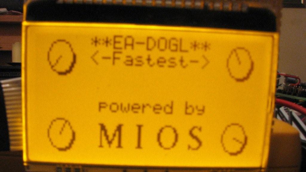
Here is a slightly better picture!
-
Hi all. I have now written a driver (well hacked one together) for these displays.... I have also written an SPI based driver for the 16x3 character LCD's. Technically it should be possible to have up to 8 of either the character or graphic displays. I was thinking about looking at combining the two into one driver but I don't think that MIOS allows mixing of GLCD/CLCD? Anyway here is a picture of the GLCD, it is 128x64, I went with the amber backlight although there are many other options just like the CLCD version. You will notice that it requires 8x 1uF capacitors, this removes the need for a high voltage supply for the LCD. Once I have sorted out and tidied-up the driver, I will commit it. Cheers Phil p.s. Apologies for the crap picture, I hadn't realised how difficult it is to take a picture of an LCD!!! IMG_0166.JPG IMG_0166.JPG