philetaylor
-
Posts
828 -
Joined
-
Last visited
Content Type
Profiles
Forums
Blogs
Gallery
Everything posted by philetaylor
-
I would check that the 3rd wire does really go to the LED. The 3rd wire on 3pin PC fans is usually a fan speed (tacho) sense wire. You may also find that it won't start on 9v but YMMV. Thanks Phil
-
If you are creating the software to actually 'play' the samples then you could have the samples triggered by a 'note on' from the midibox and then the sample player could send a 'note off' when the sample has finished. It could also send a 'note on' when it starts playing as a bit of a feedback loop (this could be used to trigger the leds). This is not exactly 'trivial' to achieve and would also require C (or assembler) programming knowledge on the midibox side. Cheers Phil
-
Hi. This morning I have received some samples of the TKD MLA-6100 series motorfaders http://www.tkd-corp.com/02_products/pdf/p02_MLA_e.pdf I have both the 60mm and 100mm versions so once I have built my MF module I will feed back on how (if) they work. Has anybody else tried TKD faders? Hopefully they should work as they don't use coreless motors....... I have no price for them yet but hopefully as they are "Low Cost Motorfaders" they should be cheap :) Thanks Phil
-
I now have a copy of the Wybron responder source for RDM and the spec pdf for RDM (ANSI E1.20) there are various changes that it looks like I should make with regard to timing etc and they also recommend that the controller contains a simple voltage divider which works as a bias circuit providing a 'mark' even when the controller is in the receive state (high impedance). I will look at this over the next few days. I think that to fully support RDM may be a bit complicated to handle within the midibox controller itself but I may write a PC program which actually handles the RDM discovery etc as then I have no memory constraints, I was thinking that the actual RDM information could be transferred to/from the PC as Sysex messages. As this is not mission-critical it wouldn't really matter if the PC was not connected during normal operation but it could be connected to handle discovery and any error conditions. p.s. Thanks for moving the thread stryd. :)
-
I didn't think it was too expensive for a 4x40 but I must be honest I haven't got much to compare it with. Are you planning to move this thread to user projects or should I just start a new one? Phil
-
If you mean buying from RS then yes I agree although surprisingly for them the display didn't have a minimum quantity of 1000 :o
-
Hi Stryd, Yes a move to user projects works for me.... You are quite right (well wrong actually) :D it is an OPTREX C-51849! Got it from RS in the UK, about £35. Cheers Phil
-
I have just updated the downloads on the wiki page http://www.midibox.org/dokuwiki/doku.php?id=midiboxdmx to the latest (still very beta) version. This version seems much more stable and I am now using a simple CRC8 check for the terminator so the chance of invalid data being received should be almost zero.. Buffering the received IIC data and making it interrupt driven also seems to have fixed most of the retry/timeout issues. I have also tried to tidy the code up a bit although there are still some very messy bits! Cheers Phil
-
I have been making many changes to the code recently, I redesigned the IIC-DMX firmware again and I have cut the DMX channels down to 256. I was tearing my hair out with 352 channels as 16 registers just wasn't enough for temporary data etc. I was concerned that the core was having to retry IIC sends a lot so I am now doing the IIC receive via an interrupt and buffering it. I am not now getting retries and it all seems much more stable. As RDM definately interests me and I can't find a (cheap) RDM compatible dimmer/fixture, I have decided to build one! I am currently designing the pcb etc for a 4 channel dimmer so this is taking quite a bit of my time (I wish I could just stick to doing one thing !!!), hopefully I can then use it for RDM testing etc. I am going to Poland for the weekend but I will post updated code soon! Phil
-
MIDIboxes in Sound & Recording magazine
philetaylor replied to sneakthief's topic in MIDIbox User Projects
It's called a Selmer Truvoice Echo 200, it works by using a tape loop and one record and 3 playback heads. The tape spins at a constant speed and using the knobs/switches you can select which of the playback heads to use and the level of feedback sent to the record head. If you can put up with the incredible amount of noise (mains and tape) you can create some great effects better than many solid state reverbs. Then again, the noise that it generated was nothing compared to the mains hum from his amp (and yes I have that as well!). Note the sexy immitation crocodile skin :) Phil (these aren't the actual units, they are in much better condition than mine, pics courtesy of www.vintagehofner.co.uk ) -
MIDIboxes in Sound & Recording magazine
philetaylor replied to sneakthief's topic in MIDIbox User Projects
Talking of reverb, I still have one of these lying around, it used to belong to my father, he was a club singer in the 50s and 60s. I used to love playing around with the different effects as a kid! -
I have found this (well I don't think it was lost....) http://www.bytecraft.com/apps/cop8capp.pdf The menu that they use in this sample appears to be quite configurable but I have been struggling to port it to SDCC.... Phil
-
Hi. I have been playing around with creating a multi-layer menu structure in C for my Midibox DMX application. Before I delve too deep into this I thought I would check to see if anyone else has created one they are prepared to share? Thanks Phil
-
I would take a look at the MIOS_AIN_PinGet(pin) function. You can call it from Init() and it returns the value of the selected pin. There are also 7bit and seperate LSB/USB functions. Cheers Phil
-
Yes I thought that but I notice on the magnulator project ( www.freedmx.org ) they have used a 6n137 between the PIC and the 75176. I suspect that it is overkill but as it is talking to devices that 'could' inject mains voltages onto the DMX bus they were just playing very safe. Especially as on their project the other end of the PIC is connected to a PC parallel port, I am not sure how much isolation the 75176 provides? Phil
-
It is annoying when proper work gets in the way of having fun isn't it :) With the code, I have made massive changes recently so I will probably just update the attachments on the other post. Everybody seems to have slightly different ideas on implementation when it comes to DMX so I would welcome any suggestions, especially wrt timing. RDM seems to expect to receive a packet within 58mS of sending the RDM request so these can easily interleave with the DMX packets and still achieve over 40 packets a second. I got a big delivery last week so I have been concentrating on the hardware recently, I got a 40x4 display as well which may be too big but at least I can display plenty of information! Cheers Phil
-
Hi. Here is a quick circuit that I have knocked-up. It should probably have a 120 Ohm resistor between pins 2 & 3 of the XLR but I haven't bothered at the moment! The benefit with the 75176 is that it has active high tx and active low rx so tx/rx can be toggled with a single data line. I suppose I should include some sort of opto isolation eventually but I can't really be bothered at the moment! Cheers Phil IIC-MIDI_IF.pdf IIC-MIDI_IF.pdf
-
I know I said that it was a medium term project but I got a bit with the bug and decided to make a start (and I haven't stopped since!!) I wasn't planning to implement comms on the the second pair as most manufacturers seem to have their own systems that are incompatible whereas RDM is a bit more intelligent. The current RDM standard (ANSI/ESTA E1.20) is actually a bit more intelligent and I am planning on trying to implement it as soon as I get a fixture that supports it. The way it works is that the controller usually streams DMX messages with a start code of 0x0. RDM uses a different start code (0x33 I think) which non RDM fixtures 'should' ignore and then stops sending DMX streams and waits a pre-defined time for the fixture to respond. I have implemented the hardware required for this by using a spare output on the p16f88 to switch the SN75176 to input so I just need to write the code (once I know what is required!). I will post the schematic for my little interface soon....... Phil
-
I know I was just musing, I will probably end up using a joystick.... I did wonder whether a laptop style touchpad would be usable? I have never really looked at them, we have loads of dead laptops at work so I might investigate further....
-
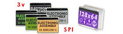
Yes that was one of my reasons for starting this project, I have used some really expensive lighting desks over the years and they are always missing the one feature that I need (or it is so complicated to find as to make it effectively missing) so I thought I would design a desk with all of the features that 'I' need and easy to navigate (although I might need to wait for MIOS32 before I get 'all' of the features!). I suppose I need to compare this with the more high-end desks when I think about the cost, I was thinking more of the sub £200 ones but as they are really just boxes with faders and very little intelligence it really is no comparison..... My thoughts with going for this case are that I should be able to easily fit at least 8 faders and plenty of other controls together with 1 or 2 nice displays..... I don't know if you have seen the thread in Parts Archive about the DOG displays that TK has got working? I was thinking of getting a couple of these, I did wonder about trying to get the graphic version working but it looks like it only has an SPI interface so I would need to bitbang SPI, maybe something else for the CORE32 with its 2 I2C/SPI ports? I like the thought of using the touch screen option for X-Y control of moving heads. Phil
-
Just a quick update (and I wanted to tell someone!). I have now got it running properly and it is much more stable. The code has gone through 3 or 4 redesigns over the last week as my coding skills and pic knowledge imroves. It took me two days to really get my head around how IIC (I2C) works! I have decided to use pseudo midi commands for the core<->iic dmx comms. For example, to change the second fader level to full, I am sending: 0xb0 0x01 0xff 0x00 Which is 'similar' to a control change midi command. This means with some bit shifting, I can send that immediately back to my PC via midi (great for debugging!) but I still get the full 8 bit resolution. I got a customs notification today so it looks like the PCB's that I ordered from SmashTV for this have arrived so I will start the 'proper' construction soon now I have a basic but functional IIC firmware! I have been looking for suitable enclosures and I found the attached from RS Components. It is a 19" wide sloped case which is designed for mounting an industrial keyboard, I was thinking of something like this but what do you think? Will I be able to fit everything in it (once I decide what everything is!). The only problem is at £45 it puts the build cost up massively. What does everyone else think? Phil
-
Yes I did think that, I wondered what the minimum break I could get away with was. I have now managed to get a timer working for the delay loop so it is much more accurate and I seem to have fixed the timeout issues as I can service the IIC within the loop. Cheers Phil
-
Here is my first very alpha release of the IIC_DMX code, I would appreciate it if any more knowledgeable assembler coders could look over it and make any suggestions/improvements. Initially I sent the whole DMX stream in one call from MAINLOOP go but this seemed to cause quite a few timeouts on the IIC so it now sends one byte at a time and returns to MAINLOOP, this did improve things quite a bit. I also tried using a timer instead of a standard delay loop as DMX512 calls for a 128uS break and a 12uS MAB between packets and I was worried that this might cause an IIC timeout but it doesn't seem to. In any case, I would like to know why my timer idea didn't work in fact my lights didn't seem to work at all with this code. I have left the code commented-out in dmx.asm. I have noticed that occasionally my el cheapo RGB LED Parcan stops working. If I reset it (or the Midibox) it starts to work again, I think that it may be a DMX timing issue. I have also written (ripped-off Midibox LC) a simple dmx controller which receives midi CC messages and sends them to DMX. It only works with the first 128 channels and is only really useful for testing at the moment. If you want to build a simple DMX out interface, you just need a 75176 connected to the USART TX pin, I will try to knock-up a circuit for what I built when I have a minute but it is really simple. Thanks Phil iic_dmx_v0.001a.zip dmx_controller.zip iic_dmx_v0.001a.zip dmx_controller.zip
-
The one-off price for the 128x64 is £12.49 and £8.70 for the 128x32, you also need a socket which costs £0.84 and a backlight, £2.98 for amber going up to £14.18 for RGB! The 3x16 character displays are also available at £5.14 each Phil
-
These dog displays look great! If anyone is interested, I have found a supplier in the UK called mmselectronics. I also notice that there are also 128x64 and 128x32 graphic modules available now, it would be really good if they worked with MB, they use the sam SPI interface as the character ones so hopefully it is possible..... http://www.mmselectronics.co.uk/lcdgraphicdog.htm Phil