

Antichambre
-
Posts
1,291 -
Joined
-
Last visited
-
Days Won
101
Content Type
Profiles
Forums
Blogs
Gallery
Posts posted by Antichambre
-
-
You can use any pin, they are all GPIO(General Purpose In/Out).
You just need declare the port of the pin as not used (MIOS32_DONT_USE_XXX) and use the GPIO_InitTypeDef. -
Hi!
It's not the subject here, but I can explain a few quickly. Phatline is right, the M16 is a 16x16 midi I/O interface, the plan is to build a expandable router using the MCAN bus to interconnect multiple couple of Core32+M16. Nx(16x16) I/O, 16x16, 32x32, 48x48 etc...The project is called "BANDMASTER", The two prototypes I've made are working... I will come back on this project once the HAARP is finished.

-
 2
2
-
-
-
Sorry not the good lib!
This one is fine:
USB1(old) FS, Device/Host, this is the one you have to use, ID is floating for Device Mode, ID to GND for HOST
41 - USB1.ID = ID pin for USB1
46 - VBUS = VBUS for USB1
43 - USB1.DP = USB1 D+
48 - USB1.DM = USB1 D-
USB2(new) HS in FS Mode, Host only.
44 - USB2.DM = USB2 D-
45 - USB2.DP = USB2 D+
49 - USB2.OC = Input for external overcurrent sensor.
50 - USB2.EN = Ouput for external power switcher -
Here the schematic you are talking about: http://www.ucapps.de/mbhp/mbhp_ainser64_interconnections.pdf
Connecting multiple AINSER64 is not a problem, you just need multiple CS lines. And will not increase the scanning time.
Any 32bits Core will do the job.
Here an example to add a CS line for AINSER8 , it's the same methods for the AINSER64.Best regards
Bruno
-
If I remember well, the pins I crossed on the first proto were J16.SI and J16.SO. J8/9 seems good on your schematic but pin 40 and 39 are still reversed!!!
39 ->J16.SO
40 ->J16.SI
More than that I added the USB Host, it doesn't appear on your pinout.
Note: USB HOST supports:- USB MIDI Device.
- USB HID Keyboard and Mouse.
attached the eagle lib.dipCoreF4_v2b.lib -
With J15.DC pin ;)

-
Pretty sure that LPC17 does not support USB Host Mode.
-
What is your core?
-
Hi Rio, Hi Andy,
If the "usb hardware controller" is an USB MIDI Device the SEQ must be set as USB Host.
Of course the SEQ needs an external power cause the MIDI Device will not provide it thru USB, and the SEQ must provide power if the Device requires USB power.
Have a good day. -
6 hours ago, rosch said:
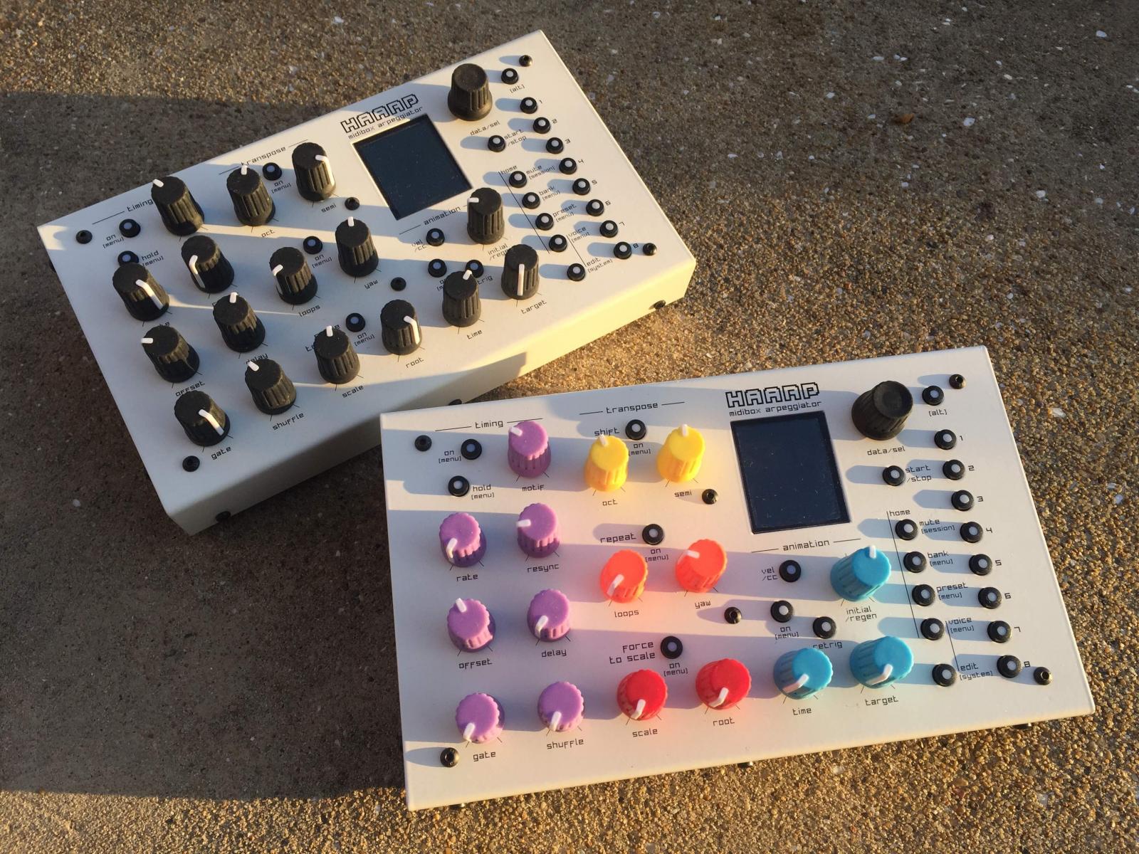
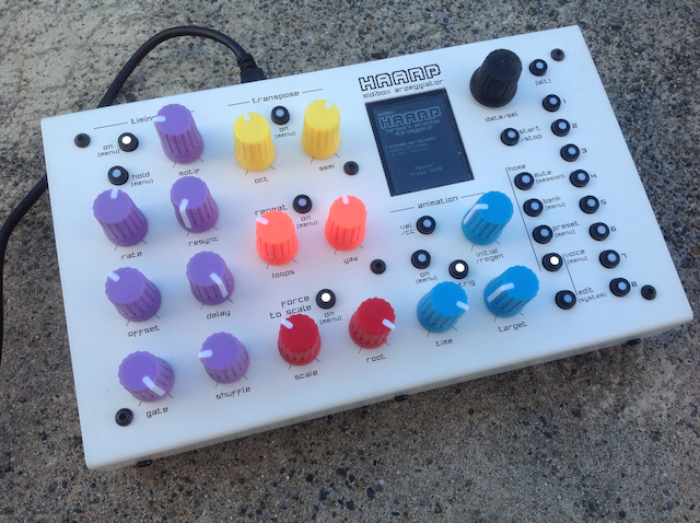
Très chic!
Merci!
6 hours ago, rosch said:I've played a lot with Xfer's Cthulu, a real arpeggiator in HW would be awesome.
This one has a pot for each parameter, it changes the game! ;)
6 hours ago, rosch said:Is there a way to get some boards / case to build one?
I will propose it soon now, I hope in the next months...
-
1
-
-
-
Remember me José Padilla's work... RIP
This track could really have had its place in a volume of "café del mar" ... And the next one as well(Caserne et forêt).
If you don't know what I'm talking about, I recommend his "souvenir" album
Anyway great chill-out sound. THX -
Put it on J16 which is 3V3, J8/9 is 5V and reserved for SRIO, J19 is 5V too.
http://www.ucapps.de/index.html?page=mbhp_sdcard.html -
Hi,
I risk being scolded because it's not exactly the subject, but it has a relation anyway ;)
At the beginning I destroyed a lot of micromatch by wanting to crimp them with a vice or an unsuitable pliers.
The official crimping pliers, probably solid gold, is extremely expensive, so I made adapters for the classic 10€ IDC crimping plier.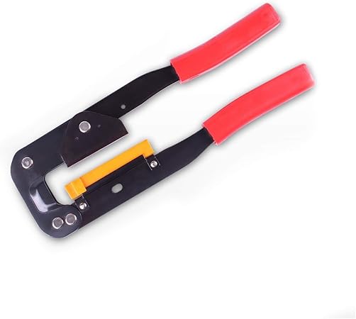


there's a ribbon guide, a male and a female adapter. It works for all type and pin number.

result is very clean!
Here the drawing, it requires a small CNC to fab it.
Peter, Andy, it's a very good idea, It would be perfect if your tester could also make the MIDI cables and Jack 3.5. :)
Very good cause it tests continuity and short-cut, Great!
Have a good WE! Best regards
Bruno
-
Like I said before, it's not something easy.
SD Card can be shifted to any predefined SPI port J16(default) J8/9(SRIO) and J19. They are unfortunately not defined over your requested pins.
Moving the SPI to your desired pins is something deeper, and the functions defined on this pins will have to be moved somewhere else then move another somewhere else again.
It's not in one unique file, it's multiple header files you have to modify in MIOS32.
There's no quick answer for your request, it needs study and time.
Best regards
Bruno
-
Hi,
All pin of the STM32F4 are General purpose I/O(GPIO) but they have limited alternative functions.
The pins for this SD Card are used for other ports/peripherals.
PC10 is used for the onboard DAC(Disco)
PC11 is the LCD Read/Write
PD2 is the UART5 RX(MIDI)
PC12 is the UART5 TX(MIDI)
Etc...
So you will have to remap more than this pins, cause the functions you remove has to move on an other pins, to get all MIOS32 ports available and avoid conflict.
I strongly suggest to follow the regular pinout and add an external SD Card Socket...Or you can download the datasheet, open a blank excel sheet and start a long adventure... ;)
Note: your CPU must be a STM32F407xx for MIOS32 to work properly.
Best regards
Bruno -
Thank you Thorsten, that's great and beautiful!
Before I was not able to slide down in my albums, it constantly went back up in the page, like an elastic ;) Now it's fine :)
Best regards
Bruno -
Too much complicated. All internal clock and PLL settings have to be change etc...
Swap the crystal or use a board which directly work with it. -
Yeah I checked it now, it seems the crystal is a 12MHz on this board, you need a 8MHz to make MIOS32 work on this.
-
DFU is a feature of the MPU not of the board. Most of STM32 provide it. Check AN3156
I use QMK Toolbox, it's made for QMK HID firmware but it works fine for me with DISCO and WAVESHARE.
No need to create a DFU file, connect the board in USB and DFU mode(BOOT0 tied to 3.3V) just load the HEX and flash. done. -
Compare the diagram and if some peripheral don't perturb MIOS32 pinout.
Seems compatible to DFU so USB pinout should be good but check.
you use the DFU(IUSB) or SWDIO to upload bootloader? -
Yep! Seems to be that one! lol

-
Hi,
It should be a 'Bankstick' issue, the EEPROM(24LC256/512) which are inside your machine. check their connection or replace it.
Best regards
Bruno-
1
-
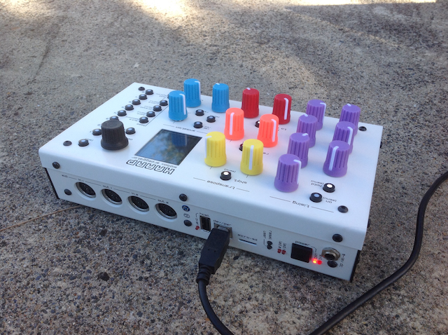
dipCoreF4 and dipBoardF4, a compact Core.
in Design Concepts
Posted
for J16 which is a SPI port
  MIOS32_DONT_USE_SDCARD
  MIOS32_DONT_USE_SPI0
Init
then to set or clear the pins you can use the macro: