

jjonas
-
Posts
422 -
Joined
-
Last visited
-
Days Won
24
Content Type
Profiles
Forums
Blogs
Gallery
Everything posted by jjonas
-
EDIT: The following is based on the pre3 release. I might be wrong (there might be a setting I've overlooked etc.), but I think that is not the problem. Here's some results I got this morning with a song that's 150 bars long and in Single mode. If I just select the song and press play, it plays fine from beginning to the end, moves location back to 1.1 on reaching the end of the file, and stops there. When a file is playing, Fast Forward works ok up to the point where you want to FF from bar 35 onwards. If you want to FF from bar 35 to 36, the player jumps to bar 2 instead (i.e. not to the beginning as I mistakenly said earlier). Below the accuracy is on bar level, as the tempo of the song I'm using (150bpm) is too fast to register sixteenths. (I could use the new and very useful tempo function here too, but maybe we can manage with this :-) Likewise: - when FFing from 40 to 41, player jumps to 7 - when FFing from 50 to 51, player jumps to 17 - when FFing from 60 to 61, player jumps to 27 - when FFing from 68 to 69, player jumps to 35 - when FFing from 69 to 70, player jumps to 1 - when FFing from 70 to 71, player jumps to 2 When a file is selected but not played and you try to FF from 35.1 to 36.1, the player jumps to 1.14 instead. With Rewind you get: - when rewinding from 36 to 35, and with all smaller numbers than this, the player works as expected - when rewinding from 37 to 36, the player jumps to 2 - when rewinding from 40 to 39, the player jumps to 5 - when rewinding from 50 to 49, the player jumps to 15 - when rewinding from 60 to 59, the player jumps to 25 - when rewinding from 70 to 69, the player jumps to 35 - when rewinding from 71 to 70, the player jumps to 1 - when rewinding from 90 to 89, the player jumps to 20 When you stop the file at 37.1 and try to rewind to 36.1, the player jumps to 1.14. Another thing related to FF/rew: when a file is playing and you press stop, and then play again, the playing continues from the same place. This is good. However, if you stop a playing file, then FF or rewind to a place you want and press play, the file starts from the beginning. It would be useful if you could FF/Rew to a place you like and then start playing the file from there.
-
I finished my build 30min ago and tested a midi file I have been making for band practice background and which I exported from Rosegarden. It works just like when Rosegarden is feeding the midi data into the synths! Just what I was looking for. TK better prepare for a beer. As to testing, obviously I haven't had too much time for that yet, but when I was testing the Rewind / Fast Forward function, I noticed that when you try to FF beyond 35 bars, the song starts from the beginning. Before further testing I'll have to read the user instructions carefully (as far as midi file playing is concerned), I'll do that on the weekend. BTW here's my build :-)
-
For what it's worth, I hope I'll have a unit running this weekend, I just need to put the enconder + buttons on it, and that's it. I'll then test the firmware at least concerning the functions I have planned using.
-
Ok thanks for the clarification. I guess it's up to you to decide whether to implement a separate loop function, I'm happy now as it turned out that SINGLE plays the selected song only once, i.e. without loop. You're right, probably 'play/pause', 'stop', 'next' and 'previous' would be useful. Maybe others have ideas for more useful controls (like 'rec'). As to tempo change and transpose, I don't think there's a need for direct live controls, at least not for me; the correct tempo and key would be defined after a few rehearsals, and once it's decided, it sticks (unless we change the singer :-)
-
The SDmidicontroller homepage boasts these "unique" :-) features: 1. In addition to just Play, you can Transpose your original midi track by + or – 24 semitones to a maximum 2 Octaves either way. 2. Tempo of the original midi file can also be changed + or - 15 steps. Eg. A 120bpm track could be played up to 75bpm faster or slower. A 250bpm track could be taken up to 325bpm or down to 175 bpm. I couldn't find them offhand having already been implemented in the MIDIO128 page. These would be really handy, there's always going to be issues about tempo and key changes when you rehearse new (or even old :-) stuff with the band. At present I'm plain-and-simple recording backgrounds and keyboard melodies on a multitracker, so if there's going to be tempo and key changes later on, I will have to record all the tracks again. As to tempo change, SDmidicontroller's 5bpm step size seems fine, though offhand one could think that it isn't harder to implement 1bpm step size..? If that's the case, I'd go for 1bpm step size. Also if I've understood correctly, there's two midi file play modes, ALL and SINGLE, ALL playing all the files in the SD card root (on repeat or not?) and SINGLE playing the selected file in a loop. If this is correct, it would be good to have a third mode that would just play the selected file, and stop when the file is played - i.e. no loop. Or maybe there could just be a separate loop flag, which would apply to both ALL and SINGLE..? Probably these won't require any new hardware, you can use the existing CS for them..? How does this sound?
-
Thanks for your answer!
-
Found this: http://lehmayr.de/e_mrmidi.htm It looks simpler than MIDIO128, anyone have experience/opinion on it..? Offhand it seems the challenge is to flash the the Atmega chip. Some guy has a version of this running on an arduino, that would make it a lot easier, but unfortunately he's not sharing the code, and doesn't seem like he's answering his viewers' questions either. Here's the "pipeorganphil" that he's referring to (sorry, the forum doesn't allow me to add more clickable URLs or media): www.youtube.com/watch?v=YNriw8VyvKM Could be the same thing that's been advertised here: www.youtube.com/watch?v=5L6oicVUcvQ ..and sold as a kit for £195(!) here: http://sdmidicontroller.com/ I think I could use arduino & USBtinyISP to program the chip, if I can translate mrmidi's programming instructions into an avrdude command.. Nonetheless, I would still be interested in an answer to my original question on what I can leave out of the MIDIO128 if for some reason I decide to try that way.
-
Hi, I would need a midi file player that I'd use to control various pieces of MIDI equipment live, basically to play the synth/keyboard stuff for a three-piece band (gtr/vx, bs, dr). I would make the files on my computer and save them on an SD card to be played on the player later. It seems MIDIO128 V3 has this feature ("integrated MIDI File Player"), but it seems like it's mostly about other stuff, and I don't know (yet :) if I'll have use for the other stuff. So the question is, does it make sense to build this just for the midi file player, or are there simpler/cheaper DIY hardware solutions around that you know of? If not, and if I'm interested only in the midi file player, what can I leave out of the MIDIO128..? DIN, DOUT, optional controls (J5A & J5B)? That would leave SD card, LCD and J10 controls. Is this correct?
-
Hi, here's a YouTube video of a DIY digital Mellotron I made, using Lee's SD card sample player project and mellotron samples found on the internet. Built into an old Philips digibox case :-)
-
This is what a programmer friend told me to do and what I did in Ubuntu 12.04. sudo apt-get install subversion Then, in terminal, cd into target folder and run svn co svn://svnmios.midibox.org/mios32/trunk/apps/synthesizers/SD\ card\ sample\ player/release/LPC1769/ Now you have LPC1769/ in your target folder. For some reason or another I had a feeling I would need to install apache2 first, but I don't know if that was necessary because I didn't try svn on the command line before I installed it. Anyway, should that be necessary, type: sudo apt-get install apache2 I wasn't really sure what I was doing but it worked, which is good enough for me.
-

MIOS32 booloader running, cannot upload app
jjonas replied to jjonas's topic in Testing/Troubleshooting
I tried uploading the MBSEQ4L hex onto the LPC board in my Windows virtual machine, and for some reason it succeeded. Now the question is whether I'll have to build an MBSEQ4L before I can get around to teaching myself how to download the Sample Player hex via svn :) -
MIOS32 booloader running, cannot upload app
jjonas replied to jjonas's topic in Testing/Troubleshooting
I tried uploading on a Windows XP (studio v 2.3.0 and MBSEQ4L_058), the result is the same, "No response from core after 16 retries!". -
MIOS32 booloader running, cannot upload app
jjonas replied to jjonas's topic in Testing/Troubleshooting
I'm using Ubuntu Linux 12.04, and trying to upload via a USB-MIDI connection. I can try it on a Windows PC too later this week. -
MIOS32 booloader running, cannot upload app
jjonas replied to jjonas's topic in Testing/Troubleshooting
Ealier I was using MIOS studio 2.1, now I tried the upload with version 2.3.0, this time there was no error message as before. But there was another problem, maybe this time it's on the hardware side, and probably something I have to try to fix. Query gives me this: Operating System: MIOS32 Board: MBHP_CORE_LPC17 Core Family: LPC17xx Chip ID: 0x26113f37 Serial: #21802121DAD04535CAB169D42000005F Flash Memory Size: 524288 bytes RAM Size: 65536 bytes Bootloader 1.008 © 2009 T.Klose This seems it's working ok. When I try to upload the hex, I get this: Reading project.hex Trying to contact the core... project.hex contains 203964 bytes (797 blocks). Range 0x00000000-0x00003fff (16384 bytes) - BL excluded Range 0x00004000-0x00031cff (187648 bytes) - LPC17 Flash No response from core after 16 retries! The led on the LPC1769 is pulsating while contact is attempted, and keep on pulsating after attempts are terminated. On the left hand window of MIOS studio the text "Upload in progress" changes into the message quoted above ("Board: MBHP_CORE_LPC17" etc), but the led pulse keeps going. I searched the forums for "response from core after retries!", there was one result, in which the problem was found in the resistor networks, which had been accidentally switched. I couldn't find the needed part in elfa.se (where I usually get my parts), so I made a network out of four 1kOhm and 10kOhm resistors. If I understood correctly, the one end of each resistor goes to a hole of their own, and the other ends are connected together in the common pin which, if you look at the core from the side of the MIDI connectors, is on the left side (pic attached).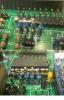
-
MIOS32 booloader running, cannot upload app
jjonas replied to jjonas's topic in Testing/Troubleshooting
Hi, sorry I wasn't clear enough, I did try to upload the app with MIOS studio via MIDI, and it was then that I got the error message I mentioned. The LPCxpresso or the separated link part of the board wasn't involved, but instead the LPC board proper was attached to the core module while trying to upload the app with MIOS studio via MIDI. It was only when I tried to reflash the MIOS32 bootloader that I used the LPCxpresso and the link board, but found that that didn't work either. -
Hi, I'm trying to upload MB SEQV4L app (version 058) onto the LPC17 board, but I get the following error message: ERROR: in line 4098: address 0x000000aa already allocated! As far as I can tell, the MIOS32 bootloader is up and running (3 led flashes), and MIOS studio recognises it as well. I don't know if it might have something to do with it that I tried uploading a non-hex file (i.e. a text file named as project.hex) in connection with the Midibox sample player user project as a means to circumvent the need to learn how to use svn to download the sample project hex file. I also tried - just to try something - to re-flash MIOS32 bootloader with LPCxpress, but that doesn't work either: the program tells me there is no board available. I have already separated the board into two, the successful bootloader flash with LPCxpress was when the board was still in one piece. Since I cut it in two the first thing I tried uploading was the text "hex" file with MIOS studio, which didn't work, and since then I haven't been successful in uploading/flashing anything on the board. However, the led flash and MIOS studio would seem to suggest that the bootloader is up and running.
-
Hi, at least hex and text almost rhyme :) but choosing 'Save link as' on the project.hex file gives the link to be saved as "filedetails.php". I guess there is no way around using Subversion to download the hex from the location given in the project wiki page. http://svnmios.midibox.org/listing.php?repname=svn.mios32&path=%2Ftrunk%2Fapps%2Fsynthesizers%2FSD+card+sample+player%2F If I read it correctly, though, the hex in the release folder hasn't been changed for 270 days, so on a layman basis it would seem it's not under feverish development, and hence it *might* seem that making a plain-and-simple downloadable hex available (like there is one for MIOS32 bootloader) would be a one-off affair..? Be that as it may, naturally I'm not in a position to demand anything from anyone in this respect, so if the developers of the project have no time, then they have no time - fair enough.
-
So I tried just copy-pasting the project.hex from /trunk/apps/synthesizers/SD card sample player/release/LPC1769/ into a text file, saving it as project.hex, and uploading it to the board with MIOS studio - I don't know if it was a good idea, but at least the smoke that drives all electronics didn't come out :-) Nothing else happened either, though. On the left hand side of MIOS studio I get: Operating System: MIOS32 Board: MBHP_CORE_LPC17 Core Family: LPC17xx Chip ID: 0x26113f37 Serial: #21802121DAD04535CAB169D42000005F Flash Memory Size: 524288 bytes RAM Size: 65536 bytes Bootloader 1.008 © 2009 T.Klose , so I suppose I've managed ok this far. However, browsing for the copy-pasted project.hex and trying to upload it, I get: Reading project.hex Trying to contact the core... project.hex contains 53136 bytes (208 blocks). Range 0x00000000-0x0000cfff (53248 bytes) - PIC Bootloader (ERROR!) ERROR: Range check failed! I don't know whether the problem is with my DIY hex file or with something else.
-
I too have problems downloading the project.hex, I don't know how to use a program to download SVN stuff, if that even is an expression that makes sense :-) Is there a reason why there is no idiot-downloadable version like there is for e.g. MBsid..?
-
A quick question on MB6582 PCBs: are they only available at SmashTV, i.e. they're not available anywhere in the EU..? I was thinking of the possibility of replacing my modular rat's nest with something a bit more trustworthy, but offhand it seems shipping etc. to Finland costs almost as much as the PCBs.
-
Here's a few patches I've made over a period of time. Some of them are more usable than others, and some are just random sound effects and such I decided to save in case I happen to need "computer chaos" style noises at some point :) The randomiser is a great help in coming up with good (or at least interesting ;) sounds. The attachment includes both individual patches and a 16 patch bank file. Here's a YouTube demonstration of the sounds: And BTW here's another YouTube clip of a song I made some time ago, it doesn't have a proper singing track yet so it's just a 20 second clip of an instrumental part. It features the arpeggio (more or less anyway) in the patch bank plus a slightly tweaked 'Nice Lead' from the "original" TK bank. (And don't mind the video :) jjonasbank.zip
-
Once again thanks for your answers! I tried TK's solution, and while I was trying it out I noticed what the original problem was: http://www.interfacebus.com/PC_MIDI_Pinout.html I had used this picture for the MIDI connector pins, and had taken it it was the MIDI socket pins as seen from the front, but apparently it was the plug pins seen from the front, i.e. I had pins 4 and 5 reversed.. in TK's schematic the pin order was clearer. Based on brief testing, it's working now. It has the 6N138 based optocoupler section from TK's schematic. @ Tim: What kind of problems might occur with the design I now have in comparison to the one you suggest..?
-
Hi, like in my previous post on this forum, I'm trying to make a MIDI thru box with this schematic: However, I have had no success, even though the circuit seems straightforward. I'm wondering whether the optocoupler is working and whether there are ways to test whether it is. When I was building MBSID, there was an LED flicker test, which I've used on the input side, and that seems to be working (i.e. the LED flickers when there is input). Is there a similar kind of LED test for the output side as well? I kind of think the phototransistor on the optocoupler's output side should be replicating the input side's signal, so can you test that with a LED too, like on the input side..? I'm using a 6N136 like in the schematic. http://www.datasheetcatalog.org/datasheet/fairchild/6N136.pdf When everything is set up, an LED between 5-6 is lit, but I'm wondering whether it should be flickering when there is input. Now the voltage between 5-6 is a constant 5VDC, and the signal at the thru box's MIDI out pins is a constant 5VDC. A broader question: why use the optocoupler here in the first place, why not just branch the input signal without it?
-
Thanks for your answers! :-)
-
Hi, I'm making a MIDI thru box as per this schematic: http://highlyliquid.com/support/library/midi-thru-circuit/MIDI-Thru-5x.png It uses the 74AC14PC hex inverter. What I could find with my local supplier, however, was only a 74AC14E, so I got that one just to try, but I now think these two are different products. However I'm not sure, and would like someone to confirm how it is. 74AC14E datasheet is here: http://www.alldatasheet.com/datasheet-pdf/pdf/26972/TI/CD74AC14E.html 74AC14PC datasheet is here: http://www.datasheetcatalog.com/datasheets_pdf/7/4/A/C/74AC14PC.shtml It would appear that the leg order of their inputs and outputs match, but their H and L (high and low..?) are reversed. Can someone confirm that the reversed H and L means that they're functionally different? And that it's no use trying to look for mistakes in my preliminary breadboard connections, because the problem is that I don't have the proper hex inverter.
