TK. Posted January 5, 2019 Posted January 5, 2019 Thanks for the hint and sorry for the trouble! :-/ I corrected the statement in the .pdf file Best Regards, Thorsten.
Antichambre Posted January 5, 2019 Posted January 5, 2019 Just now, Wapata said: Happy to help ! Bien vu l'aveugle ;)
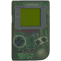
Wapata Posted January 6, 2019 Author Posted January 6, 2019 (edited) Hi ! I'm happy to say that the core is okay, i've soldered my second LCD and... it's working GREAT ! See the lasts pictures ;) https://photos.app.goo.gl/5bR4r2ivZe5dgYYW9 @TK. I've added three of them in the Gallery, please fell free to use them if you like. Edited January 6, 2019 by Wapata Picture added 1
Wapata Posted January 8, 2019 Author Posted January 8, 2019 So... It take way too much time to start using eagle. What a nightmare for a such simple board: Note that i havent check the reverse/mirror pin thing yet because I have a question first: how to make the upper solder pads to touch the border of the board ? This way it will be possible to solder this board to a 90° angle to the LCD with no wire. And then I will find how to add the ribbon connector schematic..
latigid on Posted January 8, 2019 Posted January 8, 2019 Maybe you can get it to a single layer by routing through the SIP header. For pads to the edge, you could consider a castellated pad/via. Normally the fab will charge extra for it. I'm not sure if it's a good idea mechanically; the simple pin header would be stronger. Or maybe I don't understand your idea.
Antichambre Posted January 9, 2019 Posted January 9, 2019 Workaround at osh park for castellation.https://docs.oshpark.com/tips+tricks/castellation/ Use micromatch as low profile connectoreagle files Best regards Bruno
latigid on Posted January 9, 2019 Posted January 9, 2019 I've done exactly this (with the board outline at the edge) at OSHPark. About half of my boards had missing copper though, as I suppose the router can pull the plating off.
Wapata Posted January 10, 2019 Author Posted January 10, 2019 Yes ! Theses are good tips ! I'll try by myself now with standard connectors. I have to learn and it's a useful exercise. And with the files you provided it will help too. Thanks !
Wapata Posted January 10, 2019 Author Posted January 10, 2019 Take a look: There was no chance that I could find it with the search function but... By looking deeper and deeper in the forum I fall into this tread.
latigid on Posted January 10, 2019 Posted January 10, 2019 On 1/4/2019 at 11:34 PM, latigid on said: Ah right, these can be very confusing! Also, the way CMOS labels power connections as Vcc Vdd Vss etc. can also lead to mistakes. I didn't check the pin compatibility (please check!), but this PCB might help:
Wapata Posted January 10, 2019 Author Posted January 10, 2019 Lol, it was too early in the discussion maybe Sorry
Recommended Posts
Please sign in to comment
You will be able to leave a comment after signing in
Sign In Now