ksir Posted January 25, 2023 Report Posted January 25, 2023 (edited) Hello, I am currently thinking about a version 2 of my modulbox circuits V1: the objectives are: Have the circuits manufactured by a professional (for example: https://jlcpcb.com/). Have the fronts made by a professional. -Be able to more easily share the circuits created with the community The design rules remain the same: circuits of 50 x 100 mm or 100 x 100 mm max For the potentiometers I used: RK09L1140A2U ( https://www.mouser.fr/ProductDetail/Alps-Alpine/RK09L1140A2U?qs=6EGMNY9ZYDShe59Bf8g9AA%3D%3D ) paid 0.70 euros each at the time, they cost 2.80 euros today, I'm thinking of replacing them with RK09D1130C1B ( https://www.mouser.fr/ProductDetail/688-RK09D1130C1B ) they are cheaper. Do you recommend another model / brand? I'm thinking of trying to make a footprint that accepts several kinds of potentiometers. it's possible ? does it already exist? (I work with kicad) (for caps: https://www.mouser.fr/ProductDetail/Eagle-Plastic-Devices/450-4760?qs=J4wJDGtbthoFgTzq4MR8dw%3D%3D) For the faders I used: RA6020F-10-15F2-B10K ( https://www.mouser.fr/ProductDetail/Alpha-Taiwan/RA6020F-10-15F2-B10K?qs=6TczTpqoAMVgxoAgFDSJ8A%3D%3D ) It may not be the best choice. Do you recommend another model / brand? For the push buttons I used: MEC 3FTH9 https://www.reichelt.de/fr/fr/bouton-multimec-sans-clairage-connecteur-circuit-imprim--taster-3fth9-p156904.html?GROUPID= 7587&SHOW=1&OFFSET=16&&r=1 Do you recommend another model / brand? It also remains to update the standard control surface: I'm also thinking about possibly making a 4 x 2 sparkfun pads with RGB led ( https://www.sparkfun.com/products/7836 ) I still have a lot of work. Anyone interested in this project? People who would like to help me or simply control my work? or do you have any advice or suggestions? Thanks Edited January 25, 2023 by ksir link no work Quote
Phatline Posted January 27, 2023 Report Posted January 27, 2023 (edited) control hardware yes, if it is well documentadet on the wiki (shematic, board screenshot) I too work with kicad since decades... and very sucessfull now with my actual projects - i was wondering but i planed it in kicad, and most off the boards where working 100% out off the Box (pick and place JLCPCB), ok i had a design fault on one, but that was solved with a wire-done. actual projects http://wiki.midibox.org/doku.php?id=triggermatrix5 http://wiki.midibox.org/doku.php?id=daw-ableton http://wiki.midibox.org/doku.php?id=openpad software: cant help, write my own Mios-based code, havent look into MidiboxNG - since it is a script, for me more easy to write it directly in C, (need to understand all, else i understand/learn nothing...) - so no help from this side had good expierences with jlcpcb... also with the Pick and Place service FrontPanels: maybe cheap CNC-Laser-Cutting from pcbway? https://www.pcbway.com/rapid-prototyping/CNC-machining/CNC-Laser-Cutting-Services.html suggestions? Maybe use Eurorackformat, so it can be used outside of your box too? suggestion, where usefull (wo sinnvoll) use J89 Serial Chain directly onboard (like encoder with ledring boards) to reduce wireing - a simple button board dont needs that of course.... *** if you go the Serial Chain way, then buffer the Serial chain on each module to keep the digital Signal Quality intact (very necessery) *** buffer: search for SN74LVC1G17DBVR in this shematic: http://wiki.midibox.org/lib/exe/fetch.php?media=phatline:blm16x16-shematic.pdf maybe use pick and place ready smd technologoy like i did: that makes it smaller, and less to solder, less to debug, the plastic packages stays in china, more economical special when ordering more pcbs, by that of course a module should fit all the boxes (a exotic 1 man needs it module 10times fabricated is 9 too much...) i think i dont have to say, that you should choose "Basic" Parts, and not "extendet parts" on JLCPCB, - off course on most modules you have at least one or two extendeet parts... but for example a DINX4 or DOUTX4 can be made with basic parts only... but when you also want to pick and place all the pin headers - these are extendet parts, how ever ... you may look on my last modules a bit http://wiki.midibox.org/doku.php?id=tm5-dindoutgate http://wiki.midibox.org/doku.php?id=doutx2dinx1 if you use long cables to your Displays + u use more displays then one - on the modules, use a display driver (no more walking lines) http://wiki.midibox.org/doku.php?id=displaydriver-smd what else? if you make ground or other PCB-Planes, then setup kicad that it make 1-2mm space arround solderpoints - else the Soldering Man could make shorts, or electrocemical oxidations or solder flux-low-residance could make there some problems (after years), special when the Solderstop-Pain is scratched a bit... ... and so on... PS i hate this wooble feeling off this LeMec Buttons (the last board you posted) - these Buttons are not good (for my taste) I love to work with this ones: https://www.reichelt.de/at/de/eingabetaster-schaltspannung-24v-fuer-led-sw-dtl-2-sw-p7248.html?&trstct=pos_0&nbc=1 they are expensive, but they last decades (in use, and also if you order 300 off them and let them lye arround, after 15 years they still work) They have good CLICK, like a mechanical Keyboard. your leMec Buttons are like a mixture off Rubberdome and "i have to touch this buttons into one direction X=0 Y=0 else it want switch" or you could use: https://www.midiphy.com/en/shop-details/140/4/5pcs-matias-quiet-click-tactile-switch- they are cheap but big... (aka take away a lot of Frontpanel space) or maybe you use cherry switches or simulars.... they are all 1000% better then this leMecs... ( you notice i hate them) Edited January 27, 2023 by Phatline 1 Quote
ksir Posted February 1, 2023 Author Report Posted February 1, 2023 (edited) thank you for your reply Quote suggestions? Maybe use the Eurorack format, so it can also be used outside your box? I'm working on it : I noticed you don't like the MEC buttons, I'm looking at the alternatives. maybe cherry switches, I need to find some nice caps (any suggestions?) I want to merge 2 footprints for the potentiometers: (so that I can use different potentiometers) Is this a bad idea? should I connect pads 4 to the -? thank you for your help Edited February 1, 2023 by ksir Quote
Phatline Posted February 4, 2023 Report Posted February 4, 2023 @poti; if the shaft's center is in the end on the same position - so same frontpanel holes can be used.... and: when soldering the thing: first mount the pcbs with loose potis on the frontpanel then solder it (and document this in the "how too build"... @ - : use thermal destress traces (cant remember the kicad word) when using groundplanes, so you can desolder the the poti much easier. 1 Quote
Phatline Posted February 4, 2023 Report Posted February 4, 2023 (edited) @ cherry: the switch itself you can get already from eg https://www.reichelt.de/tastaturzubehoer-c8099.html?ACTION=2&GROUPID=8099&SEARCH=*&START=16&OFFSET=16&CCOUNTRY=445&LANGUAGE=de&r=1&SID=967792150a00d890464504461a66ae529d97182e528c945af4544 caps: amazon, alibaba,.maybe.some thing like that: https://www.amazon.com/dp/B00FYO8EDC/ref=mp_s_a_1_5?keywords=flat%2Bkeycaps&qid=1675511770&sr=8-5&th=1&psc=1 https://www.cherrymx.de/en/dev.html the low profile is maybe interesting.... Edited February 4, 2023 by Phatline 1 Quote
ksir Posted February 11, 2023 Author Report Posted February 11, 2023 (edited) here is where I am at the moment: https://drive.google.com/drive/folders/1IZLVG2fVXstxGC9ZCWl0OCMjF7R1GEB3?usp=share_link i am looking for rgb leds it is listed here:http://www.ucapps.de/midibox_ng_manual_hw.html you need an external power supply. how to handle this? Thanks for your help Quote With a MBHP_CORE_STM32F4 module it's possible to drive WS2812 based RGB LEDs (usually used for LED strips) with 3x8bit resolution. The data input has to be connected to J4B.SC, ground to J4B.VS and +5V to an external PSU (required, since each RGB LED can consume up to 20 mA!) Up to 64 RGB LEDs can be driven by the core. More could be enabled if desired by increasing the number with '#define WS2812_NUM_LEDS <number>' in the mios32_config.h file, but note that each LED will consume 48 bytes and therefore the RAM limit of the STM32F4 could be reached quickly! However, 128 LEDs are working ok so far, but this could change than more firmware features are added in future. Edited February 11, 2023 by ksir Quote
Phatline Posted February 11, 2023 Report Posted February 11, 2023 (edited) at RGB-Leds > i dont know, how many you will use? which coremodule you will use? is it eurorackbased > and eurorack powerd? Which RGB-LED you will use - and what is the Voltage it needs? and so on.... i looked into your files.... some notices: @BP: dont connect the mountingholes to ground, or any other potential, best would be to make a keep out-area (sperrfläche) arround it, like i did for example here: http://wiki.midibox.org/lib/exe/fetch.php?w=600&tok=f96292&media=phatline:daw-btn-3d-b.jpg since you can plastic and/or metall standoffs to mount that pcb to the panel, you would need at least 6mm or more keepout-area.... background: you want to avoid groundloops over the frontpanel, and the risk of a electrical shock is less.... The LEDs in the diagram are connected false, the tip off the arrow should always be connected to the ground. (you should turn them 180°) which buttons do you want to use? please check the pinout off them... for me it happend that i did not connect the correct pins, so double check this.... why you made those cuts on the 4 corners? its better to make them rectangular - background: if you panelize the pcb, you have to draw a V-Grove line, the machine can only Grove in 90°, the idea, is to put 2 off this boards on one 100x100 PCB so you can save money on FAB.... way more oversight you have if you use a Groundsymbol... instead off paint Lines to a ground inside your shematic... look into "control" to see what i mean...also it makes it easyier to work with groundplanes, since this needs a NET... @Control: please open this file:Control.zip the same like above, and, you dont need that vias next to PIN 2 off the switches > Pin 2 is a via itself.... - same for Pin 1 off P2, the Problem it did not fill without your Vias: because you dont used a Ground-Net.... Pin1 - which is labeld as VDD (+) was connect to all your buttons and the pot (which is a Encoder)... normaly we connect them to ground..... VSS is ground.... so i exchanged the whole thing.... i dont know iff this is then still correct in your big picture- wiring diagram.... how ever thats the way i would make it - at least iff the Pin-Labels off the IDC Connectors are right... you should put the 4 mounting holes in the shematic, so you dont loose them when updating the PCB Also dont label your Encoder with Pot or RV >>> this is not a Potentiometer... that confused me until i realized this is a Encoder.... also the google-Drive files are a bit corrupt - the footprints where not assigned to the Shematic symbols...... when you save the project and upload it somewhere - zip it inside Kicad with "Projektdaten archivieren" - dont know the french word for it. -please overwork also your BP like/or simular like i did.... @Fader 1/2.... please open this file: Fad_2.zip shematic: also better use GND and VDD Nets.... more oversight! if you dont use a Pin off your IDC-Header (P5), then "x" them out with the blue "x" on the right side off your editor.... For what are those outer Mounting holes? they are too near to the Faders...make the pcb bigger so there is space for a Spacer/standoff, or use only the 4 inner mounting holes... which i think is enough.... again better 90° corners.... fill out your Shematics "Circuit-Field" right down - dont know the englisch or french word for "Plankopf" ... by the way you can design your own "Plankopf", so you dont see there thing like "KiCAD E.D.,A kicad 6.0.10......" keep out for mounting holes again... (see PB) dont make outher planes on VDD(+) ... mostly there can happen problems when mounting the thing to a panels, better use Ground-Planes... When looking on your FAders Footprint, and on the DAtasheet for the RA6020F then i am not sure iff the pinout is correct (the datasheet is bullshit...) but i guess you imported the Symbol and Footprint from mouser or something....then i guess its oky.... also use the design-rule check function (in a shematic and PCB-Editor) i did not looked in the other kicad-projects... but i guess its the same - a bit overwork needet.. Edited February 11, 2023 by Phatline 1 Quote
ksir Posted March 10, 2023 Author Report Posted March 10, 2023 (edited) Good morning; Thank you very much for your answers and your help which are very precious to me. I tried to correct my files according to your advice. (in the previously shared folder https://drive.google.com/drive/folders/1IZLVG2fVXstxGC9ZCWl0OCMjF7R1GEB3?usp=share_link) (I upgraded to version 7 of kicad). I'm also trying to make a PCB with silicone buttons, (see in the TO_DO folder in the folder I shared) how to create a footprint in kicad for silicone buttons, (like you did here: http://wiki.midibox.org/lib/exe/fetch.php?w=600&tok=c1a13e&media=phatline:blm16x16-pcb-3d-front.jpg) Would you be willing to share your footprint? The files you will find in the TO_DO folder are in progress, full of errors and far from finished .... if you look at them, your advice is always welcome for fun, a vision of what my future controller could look like, disregard the screen at the top right, it could have a series of oled on the top Edited March 10, 2023 by ksir Quote
Phatline Posted March 15, 2023 Report Posted March 15, 2023 yes i can share it... will take a while... do you want to use it in a button-led-matrix "scalar" way? Quote
ksir Posted March 15, 2023 Author Report Posted March 15, 2023 3 hours ago, Phatline said: yes i can share it... will take a while... do you want to use it in a button-led-matrix "scalar" way? Thanks It's mostly to look at how you designed it. I would adapt it for the sparkfun 2x2 pads i would like to use it with rgb leds Quote
Phatline Posted March 17, 2023 Report Posted March 17, 2023 (edited) hei i stripped down the BLM-Project (so it cant be cloned with out weeks off routing U B ;) ) BLM-how-to.zip and i wrote some explaination... basicly i made a Grid with a center-cross - so a single button-LED-Fottprint can be placed correct to the Rubber-Button-Grid... you may have to set a a new "zero position off the Kicad Grid" to this crosses when you place the Button-LED-Fottprint on them... this Grid also have the Holes for the PCB which are needet to hold the rubber in Position.. maybe you find a "Flip-Chip" Variant for your RGB-LED... it would be better... you should not place it on the TOP side off the PCB... because it will illuminate the Neightbar-Button-Rubbers... The Hole in the PCB where the LEDs shine thru, act as a Light-Shield... I too have to draw a RGB-LED board (for a other Task, to illuminate a Frontpanel...), since i dont have expierence with that RGB-LEDs... this will take a while... if you found a solution i would copy it from you.... At Kicad 7... didnt know there is a stable out... good to know... will update too (else i cant check your projects) Edited March 17, 2023 by Phatline 1 Quote
Dimduj Posted April 7, 2023 Report Posted April 7, 2023 Subscribing ;) Amazing project ! Keep going and thx for sharing ! Quote
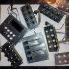
ksir Posted April 10, 2023 Author Report Posted April 10, 2023 (edited) For fun, an overview of the modules already developed and under development Edited April 10, 2023 by ksir Quote
ksir Posted April 10, 2023 Author Report Posted April 10, 2023 (edited) The module that gives me the most problem is the 4x2 Enc RGB SW Led ring Rgb https://drive.google.com/file/d/1kLTryPKwxlgYORO9NTeJ00XRjq4Sl2w4/view?usp=share_link I'm trying to use Bourns RGB + Switch Pel12T Encodershttps://mou.sr/3zJilbUhttps://www.mouser.fr/datasheet/2/54/PEL12T-777462.pdf But the wiring diagram of the leds and switches of these encoders is a challenge for me: the RGB LED matrix is also difficult. Maybe it's not possible with a matrix because of the switch ? Help and advice are always welcome. and the lack of space on will also be a PCB challenge, I may be forced to add a third sandwich panel. Edited April 11, 2023 by ksir Quote
ksir Posted April 14, 2023 Author Report Posted April 14, 2023 hello, always about 4x2 Enc RGB SW Led ring Rgb I abandoned the idea of a matrix for the rgb leds of the pel12t encoders. this simplifies the diagram. for the common anode I read here: http://midibox.org/forums/topic/20713-how-to-connect-common-anode-rgb-leds/#comment-180389 just connect the cathodes to the DOUT pins. 595s can sink current, which means they "can supply ground/0V". Thus, the output is "reversed" for common anode parts. This can be specified in MB_NG. When the 595 output is high, the LED is off. When low, the LED is on. On the other hand I still do not know how to connect the switch of the pel12t encoders to the 74hc165. normally a switch is connected between VS and D* with its switches the contact is between VD and D*. Is there a way to solve this problem in a software way? should I use a bc547 for example or other hardware solution? another possible solution? https://drive.google.com/file/d/1kLTryPKwxlgYORO9NTeJ00XRjq4Sl2w4/view?usp=share_link Thanks for your help Quote
Phatline Posted April 22, 2023 Report Posted April 22, 2023 (edited) maybe by removing the pull-Hi resistor off the HC165 Circuit, and using a Inverter on its inputs for example: https://www.mouser.at/ProductDetail/Nexperia/74HCT1G14GW-Q100H?qs=SKY61BOKKY4Uv%2FaFLc8SsQ%3D%3D https://www.mouser.at/datasheet/2/916/74HC_HCT1G14_Q100-2937184.pdf (just a example maybe there are better parts for this porpuse, and i dont know how hard to solder this one is) that would reverse Lo and Hi, and you could use this bloddy 3 LEDs ( where i think thats not a good idea, the Encoder is expensive - and not really a standard part...) but for that quick idea i would prototype that first (order a inverter, order a Encoder, make wires without pcb) ... specially iff any pull hi or pull low resistors are needet elsewhere, i guess you need a 10K pull-low resistor (to ground) on pin 3 off your Encoder then: HC165 > Inverter > Pull-Low + Pin3 since i have not much time these times, and you have plenty off modules what module i should check next? i just had a look on your 4x2 Enc RGB SW Led ring Rgb render here... and i am not 100% sure that the inbuilt RGB LEDs that enlighten the Encodersshaft dont shine on the LED-Ring and make them hard too read (maybe need some lightshielding)... by the way hard too read, those Alps Knobs are a bit big for that small Ledring - can you still see the LEDs when looking from a angle that is not 100% from top? Edited April 22, 2023 by Phatline 1 Quote
ksir Posted April 23, 2023 Author Report Posted April 23, 2023 (edited) Thank you for your involvement in my project. After studying novski's projects https://github.com/novski/Midibox/tree/master/VLR-8Enc It uses an uln2803 for the switches. I reproduced its layout, but I don't really understand how Darlington transistor arrays work. https://drive.google.com/file/d/1EW-IxclCJ1_cOeau-bTUnaOuSZ5eGdsN/view?usp=share_link I will study the solution you propose with 74HC1G14. 22 hours ago, Phatline said: just had a look on your 4x2 Enc RGB SW Led ring Rgb render here... and i am not 100% sure that the inbuilt RGB LEDs that enlighten the Encodersshaft dont shine on the LED-Ring and make them hard too read (maybe need some lightshielding)... by the way hard too read, those Alps Knobs are a bit big for that small Ledring - can you still see the LEDs when looking from a angle that is not 100% from top? you are right and will try to take your remarks into account. although I don't have a solution yet. the alps caps are pretty and I couldn't find a smaller equivalent. 22 hours ago, Phatline said: since i have not much time these times, and you have plenty off modules what module i should check next? thank you again for your involvement The encoders and silicon pad modules are far from finished. the other modules are almost ok for me, I should check them again. maybe you can watch this if you want. but if you have little time, I would not like to waste it and keep the time you can give me to really check the modules that I think I have completely finished Edited April 23, 2023 by ksir Quote
Phatline Posted April 23, 2023 Report Posted April 23, 2023 (edited) which do you think are completely finished? at Inverting - something like this: www.siglgut.at/temp/encoder-phatty.zip @ ULN2803... normally used to drive Ledrings - because off Currentlimitations off HC595ers... didnt see them on DINs normally?! @ lack off space > use 4 Layer PCBs.... dont use Thruholeparts like your 10K Resistor network - since it will steal space on all layers - better use SMD single resistors there (when you think in Multilayer), when handsolder then you can place them on top or back where you want... if pick and place then off course only on one side... Those 2x5 Pinheaders are also aviable as SMD Parts (and also on JLCPCB as Pick and Place Parts) ... Those Pinheaders in Action on a 4 Layerboard: http://wiki.midibox.org/lib/exe/fetch.php?w=600&tok=5fb4d9&media=phatline:display-driver-smd-3d-front.jpg thinking in this terms - there is plenty off space, and you could arrange then with this new space the Shiftregisters and its Datalines in a parallel manner (at least it will be easier) Edited April 23, 2023 by Phatline Quote
ksir Posted April 24, 2023 Author Report Posted April 24, 2023 9 hours ago, Phatline said: which do you think are completely finished? potentiometer :https://drive.google.com/file/d/1ThTC36WdYeexnTdHlgVoUhtVUv2OzcR3/view?usp=share_link push buttonhttps://drive.google.com/file/d/1pnDtaprQ3Mufdyg4ZW1S13UnAKqt1rC1/view?usp=share_link Fader 1https://drive.google.com/file/d/1x0nXSRO_pQJPZEVyxlxVWuarjBzKPW2m/view?usp=share_link fader 2 (connect to fader1) https://drive.google.com/file/d/1npn4KlHNovZrZ0nFLKRoN7tZ-Jd0Pf2J/view?usp=share_link all files are herehttps://drive.google.com/drive/folders/1IZLVG2fVXstxGC9ZCWl0OCMjF7R1GEB3?usp=sharing thanks to you Quote
Phatline Posted April 24, 2023 Report Posted April 24, 2023 @ potentiometer: looking good, but labeling the Holes is not necessery (i think) : 1 Quote
Phatline Posted April 25, 2023 Report Posted April 25, 2023 @ pusbutton: the LEDs in the shematic are REVERSED for example look into: http://ucapps.de/mbhp/mbhp_doutx4_32leds.pdf but in the board itself the Silkscreen for the Diode is painted correct - so if somebody just solder the PCB without looking into the Shematic - all is good, when someone look into the shematic he may be confused a bit. what type off Switch are using here > type it on the silkscreen - like you did on the Potentiometerboard. because: i see in the footprint its a le mec > then there are different types, with different Switch contacts - like you see here: 5GTH9 + 5ETH9 will work, while 5GTH9 with inbuilt LED will not work off course... i for me find the correct switch matching to your PCBs Footprint-Pinout - a bit hard... so label the type.... the rest off the PCB looks ok. 1 Quote
Phatline Posted April 25, 2023 Report Posted April 25, 2023 @ Faderboard 1 & 2 Mounting holes labeling not necessery again. rest is ok. you may could label + and - beside the 2x5 shroudet Pinheaders, so there is no chance someone reverse it in a way... in generell... normally the Nose- says all, but someone could crimp the cable incorrect... so if he controll measure, this is a good hint then for him. 1 Quote
ksir Posted May 19, 2023 Author Report Posted May 19, 2023 (edited) Thank you for these tips, I modified the files I ordered the uln2803 and the 74HCT1G14GW-Q100H to test the RGB PEL12T encoders, but I haven't managed to solve the problem yet. While waiting to solve the problem with the PEL12T RGB encoders, I developed circuits for the PEC16 encoders that I have in stock. https://drive.google.com/file/d/1HiJ8JmOTWMXAXDr4jsRvSmx43k4zEgOv/view?usp=share_link I also finished the files for the 4x2 silicon sparkfun pads.https://drive.google.com/file/d/1pefRBtEz9XU68osIdfHJXfBManKkIZye/view?usp=share_link I started to document the project https://ksir-diy.blogspot.com/2023/05/modulbox-v2.html?m=1 Edited May 19, 2023 by ksir Quote
ksir Posted June 4, 2023 Author Report Posted June 4, 2023 PCB Module DIN and DOUT: https://drive.google.com/drive/folders/1DXHAs1-3mstAdi4ANFrdSOmo7ZGawffY?usp=sharing Quote
gohan2a Posted June 25, 2023 Report Posted June 25, 2023 Hi, any news about your project? that's great idea to build in modular boxes for move or replace just one module if necessary. Quote
Recommended Posts
Join the conversation
You can post now and register later. If you have an account, sign in now to post with your account.