All Activity
- Last week
-

[S] 7x MB-LRE8x2 CS Rev 2.5 (fully stuffed with parts)
Phatline replied to Phatline's topic in Fleamarket
the rest off them are now sold to @wlinart can be closed - thx. - Earlier
-
DM sent
-
First of all sorry I am replying to an old topic. I hope there's still someone reading this topic and able to help me. Many, many years ago I built an MB-6582 with 8 real 6582A chips in it. I use an original C64C powersupply. I love my MB-6582 but it's a bit to noisy for my taste. So I'm considering buying 4 ARM2SID's to replace my 8 real sids. I think that would make it a lot quiter. If I understand correctly the arm2sid only requires 5 volts. I am not very skilled in electronics (when I built it, I simply followed the steps). I suppose I can still use my current C64C power supply, but I also read they can destroy sids (or more) when they fail, which is not very unlikely after more than 40 years. So with the new arm2sids I think I also want to replace my power supply for a modern one. Can I simply buy myself a 5V power supply and attach that to the 5V pin (number 5) of the power connector and also connect the ground pins? Or do I have to remove components from the board. The benefit of not having to remove components is that I always can decide to put back the original and use my original power supply. So what would be the simplest way to use a new 5V power supply with my arm2sids without having to remove a lot of components from the pcb? Are there schematics of the MB-6582 somewhere on the net so I (or a skilled friend) can look at the my whishes with the power supply? Also I considder recreating the control surface, because I'm not happy with the way I constructed it many year ago (the leds are not equally leveled). I think it's hard to remove all the leds. Can I still get the control surface pcb somewhere?
-

Red and black sammichSID replica w/ 2xSID emulators
sqwilliam replied to Sgw32's topic in Fleamarket
I have DM'ed for a PCB Thanks -
I am trying these as they are similar but a little smaller - will update if they work… https://uk.rs-online.com/web/p/memory-card-connectors/7636794 EDIT: It works fine - but footprint is a bit smaller so may need gluing as well if the card is going to be removed often.
-
Does anyone have spare sd card holders for the core or a suggester part substitution? (It is actually for a different pcb but is the same part as used on the stm32f4 core) 3M have stopped manufacturing them and I havent found an alternative that is the same size as SD-RSMT-2-MQ or SD-RSMT-2-MQ-WF ( I have found 9/11 pin versions which are shorter with different positions for the mounting tabs). Thanks a lot.
-

Put Waveblaster daughter board (Yamaha DB50XG) in a box?
freddy replied to SeverityOne's topic in Design Concepts
Thanks a bunch, stever! Looking forward to try it later this week when I return home. f -

Put Waveblaster daughter board (Yamaha DB50XG) in a box?
stever replied to SeverityOne's topic in Design Concepts
Prompted by a message from freddy, I've attached the project files below. They contain the source and the binaries for the bootloader and the main code. 1.05 is the latest version - there was a fix in the bootloader and the main code. I included some memory in the final hardware design but never got around to doing anything useful with it. I had plans to save one or more demo tunes as MIDI files and perhaps save some settings as profiles for different scenarios - my interests had moved on before that happened. You can find more project info at https://web.archive.org/web/20210206041027/http://www.grapevyne.com/pic.projects/ - the documentation links are all active so you can download the magazine articles and also my original source for the articles (a few errors crept into the magazine article during editing). mistralXG project files.zip mistralBoot.zip -
I designed a box in FreeCAD. The box lid clicks to the box, so it is easy to open and close it. I added a switch to connect Midi 1 with Midi2. You can download the files at weigu.lu: https://www.weigu.lu/music/midibox_hp_2x2/index.html
-

scan all inputs once after start of mios 32, send out via midi
ranger930 replied to ranger930's topic in MIOS programming (C)
thank you for your numerous answers, i will try to get it right when i find the time, br ranger930 -
Put Waveblaster daughter board (Yamaha DB50XG) in a box?
freddy replied to SeverityOne's topic in Design Concepts
Sorry to revive this long-dead thread after almost 13 years, I had MistralXG project on my to-do list for more than 10 years and I finally got to make the PCBs. Alas, meanwhile, Stever's website is down and Wayback Machine (https://web.archive.org/web/20210206041027/http://www.grapevyne.com/pic.projects/) only stores the primary site, not the linked images or other files. That means that I'm left with no firmware - anyone still has the binary HEX for PIC 18F2550 with (updated, based on the archived webpage contents, it should be v1.05)? Or even the sources, maybe? Thanks, freddy -
scan all inputs once after start of mios 32, send out via midi
jrp replied to ranger930's topic in MIOS programming (C)
i jst saw that tk answered the same question regarding mios8. The same should apply here. It works alsmost like the code i suggested above, with one big difference: I was suggesting a global variable. That does work, but is usually a good idea to avoid. The neat thing i just learned, and since we are both learning i like to share this:: What is a static variable? It is a variable that will be created once and not change over function calls. So if the code below would read "unsigned char ain_sent = 0;" without the static keyword, the variable would be recreated every tick and midi would be sent every ms. With static, this variable will be created once inside the function block (so it is not polluting the global namespace). Next time it will be 1 and the condition in the if statement will fail. ///////////////////////////////////////////////////////////////////////////// // This function is called by MIOS in the mainloop when nothing else is to do ///////////////////////////////////////////////////////////////////////////// void Tick(void) __wparam { static unsigned char ain_sent = 0; if( ain_sent == 0 ) { unsigned char pin; unsigned char num_ain = MIOS_AIN_NumberGet(); ain_sent = 1; // only sent once after startup for(pin=0; pin < num_ain; ++pin) { MIOS_MIDI_TxBufferPut(0xb0); // CC at channel 1 MIOS_MIDI_TxBufferPut(pin); // pin number corresponds to CC number MIOS_MIDI_TxBufferPut(MIOS_AIN_Pin7bitGet(pin)); } } } -
scan all inputs once after start of mios 32, send out via midi
jrp replied to ranger930's topic in MIOS programming (C)
it´s in the manual under din http://midibox.org/mios32/manual/ I cannot try this right now, but i would assume something like int my_button = MIOS32_DIN-PinGet(0); will save 1 or 0 to the variable my_button. But again, if you have a normal "digital" push button this will only work while the button is actually pressed. -
scan all inputs once after start of mios 32, send out via midi
jrp replied to ranger930's topic in MIOS programming (C)
s32 MIOS32_DIN_PinGet (u32 pin) With this function you gen poll the state of a din pin, eg when using switches in your setup. -
scan all inputs once after start of mios 32, send out via midi
jrp replied to ranger930's topic in MIOS programming (C)
The thing is: With all digital inputs you cannot get any state UNLESS a button is pressed. It would be different with actual switches that hold their state low or high. But a button or encoder has no permanent state. When you press or turn it you get a pulse that will trigger the mios callback routine. Thats it. So the direction you should be looking is to save the last state of all buttons and encoders in your code, and load it on startup. Unfortunately i am still a noob, so i cannot really tell you how to do that. But there is some example code for sd cards and bancsticks. -

Seq v4+: Left LeMec board troubles
forestcaver replied to geekraver's topic in Testing/Troubleshooting
Excellent ! Great news ! :-) -
To use Studio on newer Ubuntu Desktops you need to install the old libwebkit2gtk-4.0.so.37. To do so create a sources.list file for apt containing the following line: deb http://gb.archive.ubuntu.com/ubuntu jammy main And install the lib. sudo apt update sudo apt install libwebkit2gtk-4.0-dev After this delete the sources.list file. More infos on https://www.weigu.lu/music/midibox_hp_2x2/index.html
-

Seq v4+: Left LeMec board troubles
geekraver replied to geekraver's topic in Testing/Troubleshooting
II replaces the remaining ICs and its working! Woohoo! -
Seq v4+: Left LeMec board troubles
geekraver replied to geekraver's topic in Testing/Troubleshooting
Reflowed the ttasnsistors on the top side and now I am back to 12 LEDs on. I'm assuming the LEDs shouldn't be on, but otherwise that feels like an improvement as it means I get mattias switch events for 12 of 16. I'm also getting events for depresses on the right 4 encoders although they seem a bit random in the actual event details. I've also replaced IC2, IC3 and T3 based on advice from ChatGPT but that made no difference. -
Seq v4+: Left LeMec board troubles
geekraver replied to geekraver's topic in Testing/Troubleshooting
Thanks, perhaps I'll shoot over to the UK ;-) I've rebuilt the core board now and I'm back where roughly where I started. At least I feel confident I have eliminated the core as a possible cause; the problem must be with my LeMec board. Done some more reflowing on that board and now: - just 4 LEDs light up on power up now - all encoders generate counts when rotated but not depresses - botton left 4 buttons generate no events; bottom right four are working - mattias switches generate events for the four that have illuminated LEDs but not the rest -
 Update: MIOS Studio shows each button press with the Quad Genesis software so only LED testing is necessary. Hi everyone, I am half way through soldering the Front Panel PCB for MIDIbox Quad Genesis. I am finding that the SMT shift register ICs and SMT Resistor arrays are difficult to solder as the pads could be a little bigger as Sauraen mentioned in the wiki page and my SMT soldering isnt always accurate. This means that the connections can be unreliable and I am re-soldering each IC in order. I would like to test each LED and Button before soldering the remaining components (LEDs that go through the Front Panel, Numeric LED displays and Encoders are all thats remaining.) I have flashed MIDIbox NG to the core and can do some rudimentary tests such as lighting up all Red LEDs with the command "set dout all 1". I would like to be able configure the LED and Button Matrixes in MIDIbox NG so i can test each button and LED individually. This would really aid the troubleshooting process, verify each matrix is working before moving onto the next and will aid future builders also. If anyone could help me get started i would really appreciate it. You can find the DOUT matrix map here: http://wiki.midibox.org/doku.php?id=mbqg_fp#dout_matrix_map Thanks for your time, Smithy
 -
scan all inputs once after start of mios 32, send out via midi
ranger930 replied to ranger930's topic in MIOS programming (C)
I would like to ask my question more specifically: How can I get Mios to start the program sequence with which all inputs ( analog and digital ) are read ( without having pressed a button or turned a potentiometer ) ? This is only necessary once after the program start. Where should I insert a program code? I have already searched the entire forum and the repository for help, but have found nothing. Please help me. I have a test setup with buttons, potentiometers and LEDs and the respective inputs are read after pressing a button or turning a potentiometer. Mfg ranger930 -
Seq v4+: Left LeMec board troubles
forestcaver replied to geekraver's topic in Testing/Troubleshooting
Ah, ok - apologies - was just trying to help with some suggestions and was commenting on the shared photo. As I’m sure you know, you can often reroute lifted pads by using kynar wire or similar.... Reason I asked where you lived was that I was going to offer to look at it for you if you lived near me and wanted to drive over (shouldnt need to be said, but for clarity, not for any remuneration - just to be friendly. I have no interest in taking money for any DIY stuff - it’s just a hobby). I was making a (very) wild guess that is completely wrong that you were in the UK - again, apologies for any assumptions.... good luck. -
Seq v4+: Left LeMec board troubles
geekraver replied to geekraver's topic in Testing/Troubleshooting
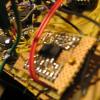
At this point I don’t think the solder you see is representative of where I started. I have reworked the board at least once, in some cases multiple times, over the past 3 weeks, and yesterday before taking this photo just fluxed everything and retouched it. It’s looking much worse than when I started, but I am just throwing stuff at the wall at this point to see if anything sticks. Right after this I decided to replace the ICs on the core and one of the tabs got damaged so I now need to replace the PCB and rebuild the core before doing anything else. And yes, I am working with a microscope. I live in Seattle, not sure what that has to do with anything though! -
Seq v4+: Left LeMec board troubles
forestcaver replied to geekraver's topic in Testing/Troubleshooting
Hi - 1. Midiphy people will send you snippets of the schematic if you ask (sub-optimal, I know, but better than nothing. When I built mine, the lack of schematics was a major concern for me too. Looking at the midibox schematics can help understand the midiphy reworking - look at the DIN shift registers and anything in that chain first for the inputs - it should be pretty solvable). (For background - I’ve built a midiphy seqv4+ and two seqv4s, one of which is very fully loaded) 2. There are issues with your soldering (sorry !) but even in that one photo there are loads of suspect solder joints. Type of solder, heat, flux, technique, etc can all contribute ! (Sorry to be negative!) 3. Do you have any magnification ? (Seeing what you are doing makes a massive difference - I use a stereoscopic microscope with a decent working distance - it’s pretty essential for me to build things reliably) 4. Where do you live ? (Your online accent implies UK !)


