FantomXR
-
Posts
1,035 -
Joined
-
Last visited
-
Days Won
22
Content Type
Profiles
Forums
Blogs
Gallery
Everything posted by FantomXR
-
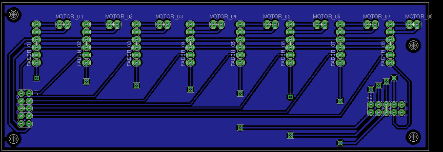
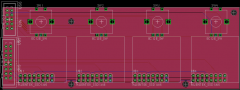
Hey people, for those of you who are using motorfader with a 4pin connector I created a PCB. 6pin connector Fader_01, Fader_02, is going to the 4pin connector on the fader plus two cables for the motor. 2pin connector Motor_01, Motor_02, etc. is going to the MF_NG pcb. J1 is going to J2 (analog inputs). J2 is going to J14 (touch sensors). Because this one is a single-layer layout, you need to connect the vias. I named the signals in eagle (use the info-tool). MF_Adapter.brd.zip
-
Hey, thanks for getting back to me. I found the dimled.ngc before, but not the other one. Thanks... I will try that today evening. //edit: A few days ago when I was in the local music shop I saw, that the company Kenton has a nice little module on the market. With this box you can convert USBMIDI to real MIDI. This is really useful, if you want to implement usb-midicontroller in your environment, that have no midi. The drawback is, that it's at 99€. TK, do you think to implement such kind of feature into the _NG too?
-
Hey people, just a short programming question: I have several LEDs connected in a DOUT_Matrix as well as several switches in a DIN_Matrix. I can easily assign one switch to LED to turn it on and off. But what I want to do is, not to turn off the LED completely. I want it to go down till, let's say, 25% of maximum brightness. How to do that? With other word: Press button --> LED goes to 100%, press button again --> LED goes to 25%. The reason why I want to do is, that I want to see the buttons even if it's dark outside. So I need kind of illumination of the buttons. Thanks, Chris
-
Still looking for this one...
-
From the album: Sketches
-
Sorry, that wasn't clear. What I meant was, to chain two led-matrix-pattern. To simplify the case: Is it possible, to set up 2x16 LEDs (=32 LEDs in total) and to program the ngc-file in the way, that the first 16 leds listen to cc (x) and value 0-63, and the second set of leds to cc (x) and value 64-127? With that setup it should be possible, to get a higher resolution on led-feedback or am I wrong?
-
Thanks for the link. Yes, I could chain two of these. That should work. Another idea is, to simply add two SR and add eight LEDs, which are assigned to a separate led-pattern. Than I scale the cc-value on the first led-stripe from 0-80 (value need to by correctly calculated) and the second stripe from 81-127. How about this?
-
For example this one: http://www.reichelt.de/Bargraf-LED-Anzeigen/GBG-2000/3/index.html?&ACTION=3&LA=2&ARTICLE=31506&GROUPID=3016&artnr=GBG+2000 I don't want to cut other bargraphs... I want it to look nice and I'm afraid, that this is not a perfect solution. Besides this, if I can get 24 LEDs running I have a higher resolution...
-
Hey, I'm wondering, if there is a chance, to add more LEDs to a led-meter. I'm asking because I can't find any 16-segment-led-meter and would need to build them by myself, which is a lot of work. I found a 20-segment-led-meter. Any informations about this? Thanks, Chris
-
Hey Thorsten, thanks for getting back to me. Okay, that makes sense. So, in a 4x8 the led would be brighter?
-
Seems like I need to bang my head against the wall to get the solution. I just try a simple thing. I have a set of LEDs but for testing I just use one. Because I want to be able to control a lot of LEDs individually, I use DOUT_MATRIX. Here is the code: So, what I do expect is that the LED connected between D7 of SR3 and D7 of SR4 lights up as soon as it receives value 127 of CC16. But instead of this it lights up and it doesn't matter what I do with the slider in MIOS Studio. If I check all other pins, I have the same effect on every pin-combination. I expect them to be 0V but they aren't. If I swap anode and cathode the led is off with cc value 0. If I move the slider to 127 it begins to light... but it's very low. I have the same effect on every pin-combination. Time to go to bed?! This shouldn't be too hard to solve.... I measured the voltages: It's 4,25V between every SR3 and SR4 pin. How come? I tried another DOUT module. Same here. I have another DOUT module here which is equipped with a ULN2803 on the first SR. With this one and this code: the voltages between the pins are as expected. BUT the led is very low... Any tipps? Thanks! //Edit: Okay... the next day... notice to myself: Read schematics carefully. I forgot to remove the resistor on the first SR in case #1. And I forgot to set the led_emu_id_offset=0 in case #2. But anyway: The led is really a lot brighter if I connect it directly to a DOUT without matrix or ULN. Even with ULN its pretty low... has it something to do that I use warmwhite LEDs? //edit: I'm using a ULN2803. So the short leg goes to D7 of SR1. Than I removed the resistor on SR2 and connected the long leg to D7 of SR2. It works, but even than it's not that bright. Is there a chance to get more brightness without connecting each LED individually?
-
Hey, I set up my motorfaders and try to get the touchsensors running. For testing I use just one fader and limit the numbers of faders in to MF_NG tool inside MIOS Studio to 1 to not get any jitter values of the open fader-ports. I connected T0 of the PCB to the touchsensor of my motorfader (ALPS coreless 100mm 10k lin.), GND to GND of the motorfader. There is nothing happening... even if I disconnect the touchsensor-cable I would expect, that I get a lot of random values, because the touchsensor port is open and not connected to anything. But: The monitor says nothing. It also doesn't care which fader-mode I use... same with touchsensor-mode and touchsensor sensibility. Well, it's late now so I will give it a fresh look tomorrow. But any tipps are welcome :) Thanks, Chris
-
m2 If someone has one motorfader left... I would be happy to buy that one :)
-
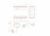
Hey people, due to the limit of space in my upcoming project I need to design a PCB, which is as small as possible. It just needs to run MB_KB, so the only things, which are necessary, are the power supply (no USB needed here) and power-schematic (not included in the attached image), the LPC itself, the 74HCT541N, MIDI Out 1, J5A (for sustain / expression) and J8/9 (for DIO_Matrix). So here is my design I just created. I need someone to confirm, that it will work like this and I didn't forget any connections. For example: How about the unused pins of the 74HCT541N? Do I need to ground them? I hope, that someone will get back to me ;) Thanks again, Chris
-
Hey, I use the 2x2 boards from sparkfun without creating a layout for my own pcb.
-
Hey, the topic says it. I'm looking for a GM5 / GM5x5x5 PCB or board. Thanks, Chris
-
Ah, you are right. Okay, I will check the fleamarket. That looks like the perfect solution.
-
Thanks for the fast replys! Okay, than I stick to the old MIDI. And: What is the smallest (in budget and dimensions) MIDI Interface with at least 4 inputs and 2 outputs? Still the midibox core or is there anything else I overlooked?
-
nIs there any sense in transmitting the midi signal in a OSC bundle via ethernet to my mac? I read through the OSC-page of ucapps and it says, that OSC is faster then MIDI... but to do this, first a MIDI signal has to be created to be packed into a OSC bundle. Is that correct? If yes, there is no advantage in speed, right?
-
Hey TK, thanks for the reply! Now I know how to use them... will be great. Best, Chris
-
Hey, I'm thinking of using this buttons in my next ucapps project: https://www.sparkfun.com/products/9277 From the schematic it seems, that they already designed for use in a matrix. But when I compare the schematic of the button pad with the one from the DIN module, it seems, that they did it the other way around. The button pads don't have a groundline, but the inputs of all buttons are connected. Is it possible to use the button-matrix of the NG anyway or do I have to connect each button separately? Can I use the "inverted" parameter in the NG for this application? Thanks, Chris
-
FYI I just ordered the electronics for an Acuna, which should fit my connections on my keyboard. I hope it will be less than 200€. I will get back with detailed informations next year ;)
-
Dear forum-members, it was already mentioned in the midiboxKB sticky thread. Some one ask, how to "midify" a wurlitzer piano. I'm interested in this to, so I ordered 10pc of 78-TCUT1350X01. So, what are the next steps? The sensor has six SMD pads. How to connect those to the DIN and how about the firmware? Thorsten, do you need a sample? Should I send you one or two of them? Thanks, Chris
-
Hi, I want to create a panel-layout for your board. Do you have an Illustrator-file or something else to import it to Illustrator? It safes work and the risks to make mistakes are much lower ;) Thanks!!
-
Hi klaus, here it is. LEDRing.brd.zip