

FantomXR
-
Posts
1,035 -
Joined
-
Last visited
-
Days Won
22
Content Type
Profiles
Forums
Blogs
Gallery
Posts posted by FantomXR
-
-
So you think that the 0,1V, that I measure on the not-active outputs wouldn't be enough to let the LEDs glow?
I don't want to rewire the whole array. Just the last LEDs of every row, which goes to D0:D3 on SR1 and the last LED of every coloumn, which goes to D0:D7 of the other SRs. I don't plan to rewire the connections between the LEDs.... I hope I don't have to, because this took me two days...
Anyway.... I will get back to you as soon as I rewired the connections and setup the NGC.
Thanks!
-
So your suggestion is, to connect all LEDs to the two DOUTs? Maybe I should start, setting up another matrix of LEDs, which is much smaler.. lilke 4x4 or so. Just for testing and before connecting all the 64 LEDs again to the DOUTs.
I want to change to ribbon cables so I need to rip up a few.... or a few more.... cables the next days. Got a gig on upcoming saturday so I don't think I will be able to do this tomorrow.
But the problem that I reported remains: I think, because of the small voltages at the outputs, which are not active, the LEDs will light up low. But that's not what we want, is it? I thought, it's possible, to switch all LEDs completely off. Where does these voltages come from?
-
Okay!
Thats my code:
RESET_HW
LCD "%CHello World!"
EVENT_BUTTON id=2 fwd_id=LED:1 type=NoteOn key=36 lcd_pos=1:1:1 label="Button #%3i: %3d" button_mode=ToggleI connected a DIN to my core with a button attached. This one works fine. Right after the DIN I put my DOUT but I removed the ULN.
Now I'm able to switch on / off the outputs of the first SR by changing the "fwd_id=LED:x"-number. I measure 5V when I press the button. And 0V when I press it again. So... it seems everythings fine here...
//edit: I put back the ULN into his socket. I'm able to switch on / off the outputs of the ULN. The output that's "active" has 1,2V, the other have those small voltages like in the picture above... like 0,1V. By pressing the button again, everything goes to 0V. I'm wondering, why the other outputs also get small voltages... this should be 0V or did I miss something?
-
Hey,
thanks for the hints.
You are right. I will solder off all the wires and use ribbon cables. I'm busy for today so I don't have much time to test. But I will come back to you shortly.
But to answer your questions:
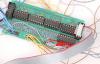
Yes, this one is SR1. I disconnected all other DOUT / DIN modules from this one in the picture.
I also checked the cable on J1. The cable makes a half twist and goes not 1:1. This should be correct. The 74HC595 are getting their 5V...
I really want to get this machine running in the next days. So I hope, I don't strain your attention to much.
Thank you very much!
-
As I understand it, without button_mode=Toggle, you should see 5V when key#36 is pressed and 0V when it is released.
With button_mode=Toggle, press the key ->5V, press the key again ->0V, and so on.
Either way we want to see 0v and 5V on the output of the DOUT under midi control.
The 5V at the output of the SR / the input of the ULN are always there. It doesn't matter, if I press a key or not.
I need to replace "type=NoteOn key=36" with "type=cc cc=1" to get something out of the ULN. I get 1,2V out of the ULN to D7 by pulling up the CC1 fader in MIOS Studio. I never got 5V out of the ULN. If I leave "type=NoteOn key=36" I measure 0V with pressed AND depressed #36 at D7.
-
Hey!
I disconnected the rows from the DOUT but leave the coloums connected. Here is what I did:
I used this code:
#row 1
EVENT_BUTTON id=1 fwd_id=LED:1 type=NoteOn key=36 button_mode=Toggle
#row 2
EVENT_BUTTON id=2 fwd_id=LED:2 type=NoteOn key=37 button_mode=Toggle
#row 3
EVENT_BUTTON id=3 fwd_id=LED:3 type=NoteOn key=38 button_mode=Toggle
#row 4
EVENT_BUTTON id=4 fwd_id=LED:4 type=NoteOn key=39 button_mode=Toggle
#column 1 red
EVENT_BUTTON id=5 fwd_id=LED:9 type=NoteOn key=40 button_mode=ToggleI measured the input of the ULN, which is 4.9V. I measured the outputs = 0V. I pressed key #36 and measured the outputs again = 0V.
I changed the code to:
#row 1
EVENT_BUTTON id=1 fwd_id=LED:1 type=cc cc=1
#row 2
EVENT_BUTTON id=2 fwd_id=LED:2 type=NoteOn key=37 button_mode=Toggle
#row 3
EVENT_BUTTON id=3 fwd_id=LED:3 type=NoteOn key=38 button_mode=Toggle
#row 4
EVENT_BUTTON id=4 fwd_id=LED:4 type=NoteOn key=39 button_mode=Toggle
#column 1 red
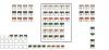
EVENT_BUTTON id=5 fwd_id=LED:9 type=NoteOn key=40 button_mode=ToggleI measured the outputs = 0V. I pulled up the CC1 fader in MIOS Studio and measured again. D7 is at 1,2V. All the other outputs have a small voltage too. See picture attached.
I'm really not sure, where to look for the mistake. I also tested it with another DOUT module. Same here. Also it seems, that button_mode=Toggle isn't working at my side. I also tried to again upload MF_NG without any results.
-
Thanks for your help.
I tried, what you were suggesting.
At first I copy&past your code into my NGC. By pressing #36 nothing happened. Also pressing #40 all LEDs stay dark.
I replaced "type=NoteOn key=40" with "type=cc cc=1". When I use the slider, I can switch on and off a array of 4 LEDs. This is not working on the rows. If I replace "type=NoteOn key=36" with "type=cc cc=1", nothing is changing. It's still not working...
I measured the rows and it's at 2,8V.
-
I'm suggesting you take a step by step approach to discovering what is going on with your LED array.
I've made some very specific suggestions.
It is up to you if you want to do it, or not.
Maybe you got me wrong?! Of course I want to do it, but I'm not sure, how to code that...
-
I'm not so much experienced with coding. So please excuse my "bad coding".
I tried just this
EVENT_LED id=1 type=CC cc=16 rgb=0:0:15
Nothing happens, when I use the slider. Same with keys... everything is dark.
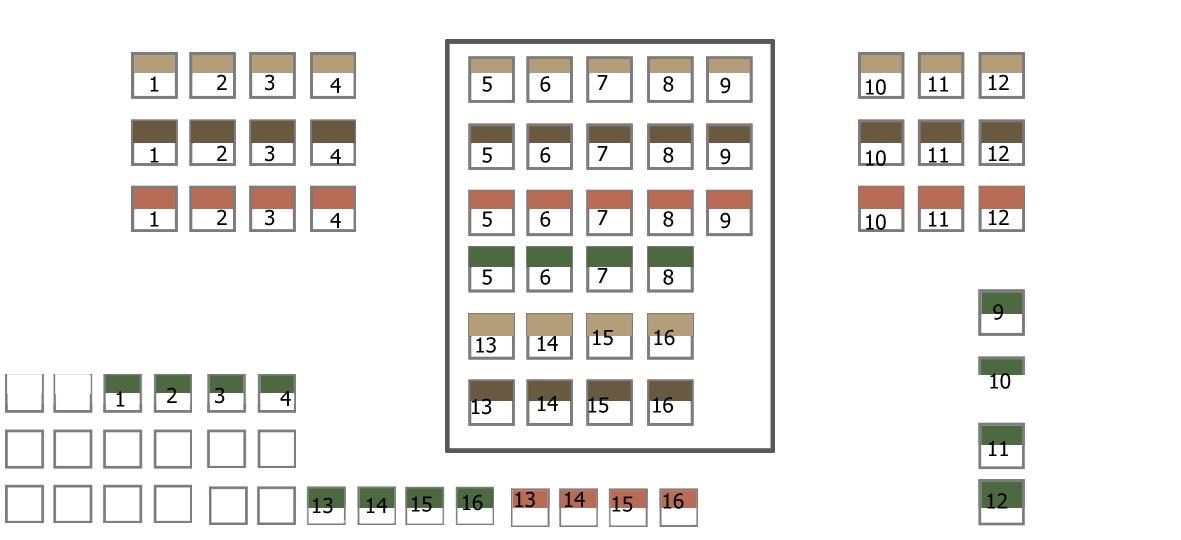
//edit: I did draw a diagram, that shows, how I connected the LEDs. The color of the boxes are the rows, the number is the led.
-
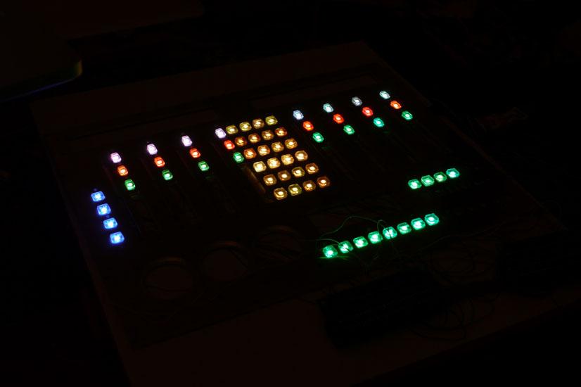
As you can see in the picture attached, I'm able to set the color for every single LED.
Because my wiring was very (!) time consuming, I don't want to rip it all up. And I don't get exactly, what you mean. Maybe you can explain more into detail?
I really appreciate your help!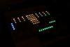
-
And another question:
I now connected all red and green LEDs.I have a problem: I can't swich the LEDs off. I tried rgb=x:x:x to 0:0:0 and also tried to set the value to 0. The LED are still on... they are low, but they are on....
-
Still looking for DOUTs...
-
Works perfect!! Thank you! ;)
Is it possible to set up an encoder to scroll / fade through all the different possible colors?
-
Hey!
Is there someone, who has a 49-76key keybed left?
Looking for a qualitykeybed from fatar, roland, yamaha, etc.
I'm located in Germany.
Thanks!
Chris -
Thank you so much!
I will keep you updated! -
Thanks for this hint!
I will check this out tomorrow and give you a status update.Should I take 82Ohm or standard 220Ohm resistors?
But the code should work you say?
-
Okay, here we go!
I now connected 4 rows with 16 LEDs per row to D0:D3 of SR1. For now I just connected eight (8x4) of the green LEDs to D7:D0 of SR2 to see, if it's working.
I connected the DOUT with the core. The first SR has no resistors, just bridges. SR 2-4 are equiped with ULN2803. I put a 82Ohm resistor to each output (so, 8 resistors).
I tried this code:
# In this demo we configure individual brightness levels for the LEDs
RESET_HW
LCD "%C@(1:1:1)RGB Demo #1"
# In the SR configuration we assume that the DOUTs are directly connected to J8/9 of the core
# they emulate led functions
DOUT_MATRIX n=1 rows=4 inverted=0 sr_dout_sel1=1 sr_dout_r1=2 sr_dout_g1=3 led_emu_id_offset=1001
# note: actually the sr_dout_sel1 in DOUT_MATRIX could be removed,
# since DIN_MATRIX already outputs the selection pulses there
# this is just for the case that somebody copy&pastes the definition...
# LED Functions (assigned to the same events like the buttons)
EVENT_LED id=1001 type=NoteOn key=36 chn=1 rgb=15:0:0
EVENT_LED id=1002 type=NoteOn key=37 chn=1 rgb=15:0:0
EVENT_LED id=1003 type=NoteOn key=38 chn=1 rgb=15:0:0
EVENT_LED id=1004 type=NoteOn key=39 chn=1 rgb=15:0:0
EVENT_LED id=1005 type=NoteOn key=40 chn=1 rgb=15:0:0
EVENT_LED id=1006 type=NoteOn key=41 chn=1 rgb=15:0:0
EVENT_LED id=1007 type=NoteOn key=42 chn=1 rgb=15:0:0
EVENT_LED id=1008 type=NoteOn key=43 chn=1 rgb=15:0:0
EVENT_LED id=1033 type=NoteOn key=44 chn=1 rgb=0:15:0
EVENT_LED id=1034 type=NoteOn key=45 chn=1 rgb=0:15:0
EVENT_LED id=1035 type=NoteOn key=46 chn=1 rgb=0:15:0
EVENT_LED id=1036 type=NoteOn key=47 chn=1 rgb=0:15:0
EVENT_LED id=1037 type=NoteOn key=48 chn=1 rgb=0:15:0
EVENT_LED id=1038 type=NoteOn key=49 chn=1 rgb=0:15:0
EVENT_LED id=1039 type=NoteOn key=50 chn=1 rgb=0:15:0
EVENT_LED id=1040 type=NoteOn key=51 chn=1 rgb=0:15:0
EVENT_LED id=1009 type=NoteOn key=52 chn=1 rgb=15:15:0
EVENT_LED id=1010 type=NoteOn key=53 chn=1 rgb=15:15:0
EVENT_LED id=1011 type=NoteOn key=54 chn=1 rgb=15:15:0
EVENT_LED id=1012 type=NoteOn key=55 chn=1 rgb=15:15:0
EVENT_LED id=1013 type=NoteOn key=56 chn=1 rgb=15:15:0
EVENT_LED id=1014 type=NoteOn key=57 chn=1 rgb=15:15:0
EVENT_LED id=1015 type=NoteOn key=58 chn=1 rgb=15:15:0
EVENT_LED id=1016 type=NoteOn key=59 chn=1 rgb=15:15:0
EVENT_LED id=1041 type=NoteOn key=60 chn=1 rgb=4:15:0
EVENT_LED id=1042 type=NoteOn key=61 chn=1 rgb=4:15:0
EVENT_LED id=1043 type=NoteOn key=62 chn=1 rgb=4:15:0
EVENT_LED id=1044 type=NoteOn key=63 chn=1 rgb=4:15:0
EVENT_LED id=1045 type=NoteOn key=64 chn=1 rgb=4:15:0
EVENT_LED id=1046 type=NoteOn key=65 chn=1 rgb=4:15:0
EVENT_LED id=1047 type=NoteOn key=66 chn=1 rgb=4:15:0
EVENT_LED id=1048 type=NoteOn key=67 chn=1 rgb=4:15:0
EVENT_LED id=1017 type=NoteOn key=68 chn=1 rgb=15:4:0
EVENT_LED id=1018 type=NoteOn key=69 chn=1 rgb=15:4:0
EVENT_LED id=1019 type=NoteOn key=70 chn=1 rgb=15:4:0
EVENT_LED id=1020 type=NoteOn key=71 chn=1 rgb=15:4:0
EVENT_LED id=1021 type=NoteOn key=72 chn=1 rgb=15:4:0
EVENT_LED id=1022 type=NoteOn key=73 chn=1 rgb=15:4:0
EVENT_LED id=1023 type=NoteOn key=74 chn=1 rgb=15:4:0
EVENT_LED id=1024 type=NoteOn key=75 chn=1 rgb=15:4:0
EVENT_LED id=1049 type=NoteOn key=76 chn=1 rgb=8:15:0
EVENT_LED id=1050 type=NoteOn key=77 chn=1 rgb=8:15:0
EVENT_LED id=1051 type=NoteOn key=78 chn=1 rgb=8:15:0
EVENT_LED id=1052 type=NoteOn key=79 chn=1 rgb=8:15:0
EVENT_LED id=1053 type=NoteOn key=80 chn=1 rgb=8:15:0
EVENT_LED id=1054 type=NoteOn key=81 chn=1 rgb=8:15:0
EVENT_LED id=1055 type=NoteOn key=82 chn=1 rgb=8:15:0
EVENT_LED id=1056 type=NoteOn key=83 chn=1 rgb=8:15:0
EVENT_LED id=1025 type=NoteOn key=84 chn=1 rgb=15:8:0
EVENT_LED id=1026 type=NoteOn key=85 chn=1 rgb=15:8:0
EVENT_LED id=1027 type=NoteOn key=86 chn=1 rgb=15:8:0
EVENT_LED id=1028 type=NoteOn key=87 chn=1 rgb=15:8:0
EVENT_LED id=1029 type=NoteOn key=88 chn=1 rgb=15:8:0
EVENT_LED id=1030 type=NoteOn key=89 chn=1 rgb=15:8:0
EVENT_LED id=1031 type=NoteOn key=90 chn=1 rgb=15:8:0
EVENT_LED id=1032 type=NoteOn key=91 chn=1 rgb=15:8:0
EVENT_LED id=1057 type=NoteOn key=92 chn=1 rgb=15:12:0
EVENT_LED id=1058 type=NoteOn key=93 chn=1 rgb=15:12:0
EVENT_LED id=1059 type=NoteOn key=94 chn=1 rgb=15:12:0
EVENT_LED id=1060 type=NoteOn key=95 chn=1 rgb=15:12:0
EVENT_LED id=1061 type=NoteOn key=96 chn=1 rgb=15:12:0
EVENT_LED id=1062 type=NoteOn key=97 chn=1 rgb=15:12:0
EVENT_LED id=1063 type=NoteOn key=98 chn=1 rgb=15:12:0
EVENT_LED id=1064 type=NoteOn key=99 chn=1 rgb=15:12:0But... no lights... nothing happens......
any suggestions?
-
Hey TK,
yes, I already realized that by myself. I now wanna use single square-LEDs which I connect in a matrix.
I will get the CCs from bidule. That works on my iPad perfect.
-
I'm really not much into SysEx, but just a short question:
Is it possible to send SysEx from a computersoftware (like MAX or plogue bidule) to the core, which changes the LCD message? If yes: Is there a kind of "sysex-creator" for text?I'm asking because Mainstage is not able to send tracknames (in difference to logic). I want to use Plogue Bidule instead to do this after every patch change. Will be a lot easier, than programming patches on the MB_NG.
-
Hey thorsten, That makes sense. But is there a way to calibrate the exp pedal without a crashing software? :) I want the pedal to go from 0 to 127. Thanks!
-
As mentioned in a thread (MB_NG) I've tried to connect my expression pedal to the analog ins of the LPC.
It seems to work, but I've got jittering values (about cc-value 122 in one direction, 6/7 in the other) . I tried to connect a resistor between 3.3V and the pin on the exp-pedal. Same here. I saw, that there is a "calibration" function in the menu. When I try to calibrate, the monitor gives me a LOT of informations. But I can see no change if I pull down the exp-pedal. At this point the application (or MIOS Studio) hangs and the only thing I can do, is plug off the USB from the computer and restart the application.
Is there a way to manually calibrate the pedal? Because now the monitor says, the min_value of the analog_in is 0 and the max_value is 255.
-
Thanks!
I will try that... hopefully tomorrow morning ;)//edit: Moved it to MB_KB Thread. I forgot that my keyboard is running on MB_KB and not MB_NG.
-
Thanks for your help!
Another one: How to connect an expression pedal to the LPC? It has a stereo jack, so I assume, I need to connect GND to GND, tip and ring to a separate analog-in on the LPC. But how to assign them in the NGC so it behaves like one controller? -
Hey,
I just ordered a bunch of those bargraphs:
but now I'm wondering, how to connect them to the DOUT, because some LEDs are using the same pin for supply and ground, if I get it right...
Thanks,
Chris

Connecting RGB LEDs
in MIDIbox NG
Posted
Yes, I'm sure with that. I checked every LED before soldering.