

FantomXR
-
Posts
1,035 -
Joined
-
Last visited
-
Days Won
22
Content Type
Profiles
Forums
Blogs
Gallery
Posts posted by FantomXR
-
-
Hey,
I'm thinking of using this buttons in my next ucapps project:
https://www.sparkfun.com/products/9277
From the schematic it seems, that they already designed for use in a matrix. But when I compare the schematic of the button pad with the one from the DIN module, it seems, that they did it the other way around. The button pads don't have a groundline, but the inputs of all buttons are connected.
Is it possible to use the button-matrix of the NG anyway or do I have to connect each button separately? Can I use the "inverted" parameter in the NG for this application?
Thanks,
Chris
-
FYI
I just ordered the electronics for an Acuna, which should fit my connections on my keyboard. I hope it will be less than 200€.I will get back with detailed informations next year ;)
-
Dear forum-members,
it was already mentioned in the midiboxKB sticky thread. Some one ask, how to "midify" a wurlitzer piano. I'm interested in this to, so I ordered 10pc of 78-TCUT1350X01.
So, what are the next steps? The sensor has six SMD pads. How to connect those to the DIN and how about the firmware?
Thorsten, do you need a sample? Should I send you one or two of them?
Thanks,
Chris
-
Hi,
I want to create a panel-layout for your board. Do you have an Illustrator-file or something else to import it to Illustrator? It safes work and the risks to make mistakes are much lower ;)
Thanks!!
-
-
Thank you very much duggle! I'm happy now :)
-
Ah, got it! I adjusted the trimpot. Now I have 3.3V on pin 1 depressed and 0V when pressed! I think, this is how it should be, right?
-
In the meanwhile I checked with MIOS Studio and it's working really well now!! Thank you so much... that is awesome! :)
But it seems that it makes no difference on which value I put the trimpot. It's now full turned "on" so 500k and it's working fine like this.
-
okay, I wired the 10k to GND. Now I measure 0,51V depressed and 0,01V pressed.
But I connected the pot like a pot.... I change this... wait a second ;)
//edit: Okay, I changed the wiring. One side of the pot goes to 3.3V, the wiper goes with 180k to LM and with 10k tied to ground. I measure 0,61V and 0,08V between GND and pin 3. I'm wondering what we want to reach or what do we want to get. I'm also not sure, what sense the trimpot has. By changing the trimpot, the voltages stay the same.
Thanks for your help!
-
I added the pull up at first.
On pin 3 I measure 0,61V depressed and 0,09V pressed.
I will add the 10k between pin of trimpot and GND.
-
I don't have the 1k pullup. I will add this.
I was not sure, if Rg2 is still necessary, because I use a trim pot. I can't see Rg2 in your examples too. But I can add this anyway.
-
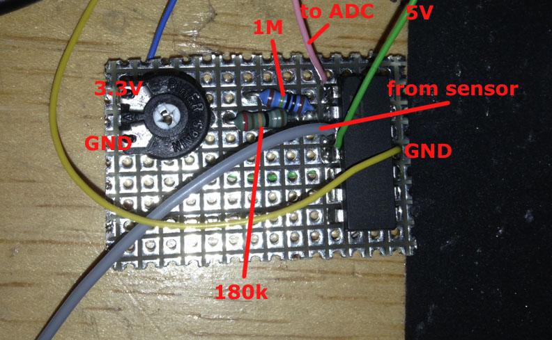
I bought the parts today and put them together.
Please see attachment.
One side of the sensor goes to the LM, the other one to GND on the core.
I double checked the connections on the board...
With this circuit connected to the core I measure 0,75V between GND and wiper of the pot and 0,62V between GND and pin 2 of the LM. But I measure nothing between GND and pin 1. Even if I press and hold a key.
Do you see a mistake?
-
Ah, okay! Now it's getting clear.
To summarize the result:
Rf = 1M
Rg1 = 180k
Rg2 = 10k
R1 = 500k trimpot
Correct? ;)
-
Hey!
I measured 0,09V and 0,6V.I put it in your spreadsheet and I get 4900R as a result. So I just put the parts like in the blog entry example together and set the trimpot to 4900R.
3.3V on the schematic goes to 3.3V anywhere on the core.
5V on the schematic goes to 5V anywhere on the core.
"Wiper" on the schematic goes to one side of the sensor.The other side is connected to ground.Is that correct?//edit: But why the second resistor (Rg1AMod) in the mod-wheel example? -
Can you take a photo (or scan) and post the schematic?
Yes, there is a simple circuit and some calculations, but I'd like to see the circuit that you have first, thanks.
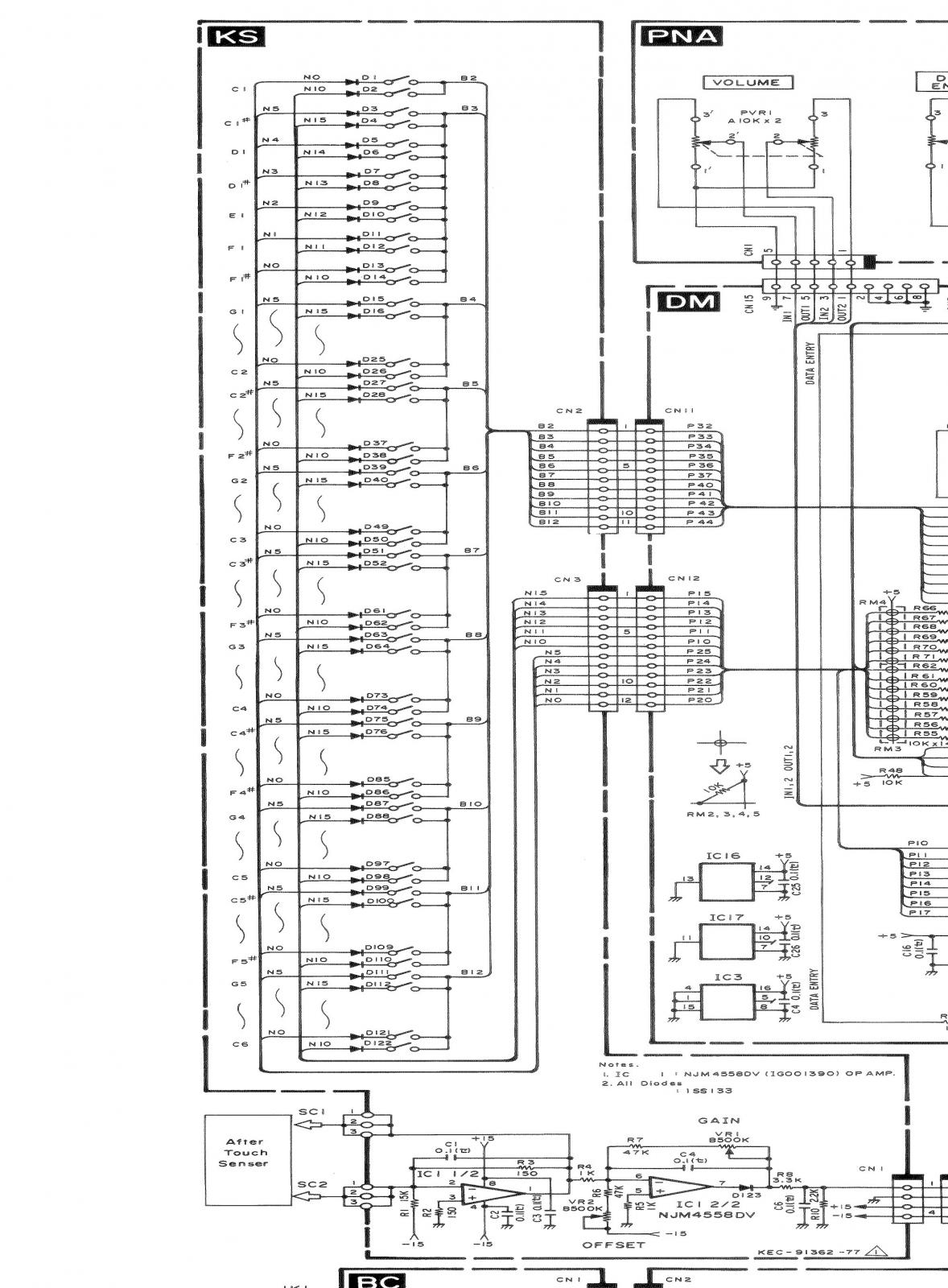
Hey,
of course, here is the excerpt of the schematic (bottom).
@TK: That sounds interesting. I'll order a few and give you feedback as soon as they are arrived.
-
Hey!
I don't have detailed informations too. Just the schematic, but it says nothing about the current...What do I have to do exactly by using an op-amp? Do you have a little schematic for that?
-
Do I need to "enable" 5V on J5 anywhere or should I use the 5V of a J8/9 instead?
-
I have the original schematic here. There is a little circuit, which amplifies the aftertouch signal and invert it afterwards. This circuit needs 15V. So I don't think, that 3,3V will damage the device...
So, I should use a smaller resistor?
-
I measured:
not pressed: 0,43V
top: 0,30-0,33V
middle: 0,13-0,15V
other end: 0,05-0,07V
Thank you!
-
I have no probs with Pitch and Mod too! I use also the core ADC for them... but with aftertouch it's more difficult... I will try, what you suggest.
-
Okay, I think, the best way is not to use the ICs on the PCB in my DX11 keyboard.
Instead I connected the aftertouch stripe directly to the core. The strip has round about 150Ohm depressed. Pressed it goes to 20-30Ohm. I put J5.A0 of the core on one side of the strip and J5.VS on the other one. I put a 1k resistor between 3.3V and A0.
To get values I can work with, I assigned J5.A0 to a cc-event. I set MIOS in debug mode and set the pinrange in the ngc-file.
Now I get jittering values. Depressed I get values between 114-125, by pressing a key it jitters between 0-15. Is the jittering a problem of the AINs of the core? What do you recommend? I don't wanted to build in a AINSER64 just for one controller ;) So if there is another solution, I'd be happy to hear it.
//edit: I saw there is a AINSER8. Is this available? Can't find it at AVIShowtech...
-
I solved the problem by using Midibox_NG. It seems, that it's not the same driver on NG and KB.
-
Hey people,
for my keyboard project I'm not using a DIO-Matrix-Modul, but a DIN and a DOUT-Modul. I configured the KB-app like this (excerpt):
[9275.100] kb 1 debug off
[9275.100] kb 1 midi_ports 0x1011
[9275.100] kb 1 midi_chn 1
[9275.100] kb 1 note_offset 21
[9275.101] kb 1 rows 12
[9275.101] kb 1 velocity on
[9275.101] kb 1 release_velocity off
[9275.102] kb 1 optimized on
[9275.102] kb 1 dout_sr1 1
[9275.102] kb 1 dout_sr2 2
[9275.103] kb 1 din_sr1 1
[9275.103] kb 1 din_sr2 2
[9275.103] kb 1 din_key_offset 40So... I'm wondering, that I get "Note On"s too, if I use SR 3 and 4 of the first DOUT... why that? I thought, that they were "disabled". If not, is there a chance to disable them for the first kb?
The reason why I'm asking this:
The keyscanning of my keyboard is a bit tricky and this is the only solution I can get this to work. I want to use kb 1 and the first two SRs of the DOUT to scan all C#-F#, kb2 and the other two SRs to scan all Gs-Cs on my keyboard. The DINs are the same for both kbs. But if I configure the app like this, I get two notes everytime I hit one key...Thank you !
Chris -
You don't need sockets on the core normally.
If you want to have the LPC removable, you can put sockets under this one.
Sparkfun buttons: Matrix possible?
in MIDIbox NG
Posted
Hey TK,
thanks for the reply!
Now I know how to use them... will be great.
Best,
Chris