

Sauraen
-
Posts
460 -
Joined
-
Last visited
-
Days Won
26
Content Type
Profiles
Forums
Blogs
Gallery
Everything posted by Sauraen
-
From the album: MIDIbox ASIDITY
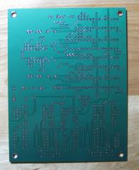
The back of the boards. -
From the album: MIDIbox ASIDITY
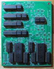
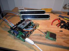
I just threw in the chips. They're not soldered yet--there are 650 holes in each board! -
From the album: MIDIbox ASIDITY
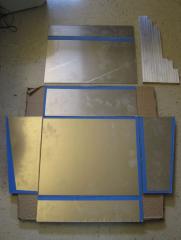
This is the final (ordered!) version of our design for the SIDFB module, containing two SIDs, six channels of digitally controlled feedback and audio outputs per SID, and a CD4052-based circuit to switch between four pairs of filter capacitors. -
From the album: MIDIbox ASIDITY
-
From the album: MIDIbox ASIDITY
-
From the album: MIDIbox ASIDITY
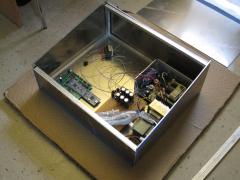
I just threw in the power supplies we're using for scale. +5V @ 9A, +/-5V @ 2A, +12V @ 4A. -
From the album: MIDIbox ASIDITY
I haven't drilled the screw holes yet, so this is held together by gravity and Scotch tape. -
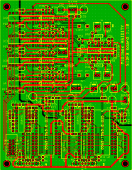
We just ordered the custom SIDFB module boards. Each contains two SIDs, plus for each, a CD4052-based circuit to switch among four pairs of filter capacitors by digital control, and the six channels of digitally controlled audio attenuation/feedback. We will put up a video once we receive the boards, showing them off as well as our breadboard with 8580s (instead of the 6581s we've been testing with so far).
-
Also maybe pin 6. As far as I can tell pins 15 and 16 are just connected to J6/7 which are not used here, but pin 6 is connected to the BankSticks.
-
Yes, those were the right chips. Still on this same track of possible solutions, could you check for bad solder connections on their sockets? If you have extra BankStick chips, you might try those instead (but I wouldn't go ordering new ones except as a last thing to try). Also, I'm not specifically familiar with the sammichFM firmware, but probably when you just turn it on with no BankSticks it will not produce any sound because it has no patch, that's why I suggested you make a patch using the front panel and try playing that. But the fact that reinstalling everything didn't help makes me think it's a hardware thing. Another line of inquiry: When it was failing at first, did it seem to be skipping MIDI messages or was the sound itself failing? That is, the core writes to the OPL3 telling it to start and stop producing sound; if the core was dropping MIDI messages or there was anything wrong on the core side, you would tend to get notes stuck on or otherwise get sounds out of the OPL3 but not be able to properly control them. This question might help narrow down whether the problem is in the core/BankSticks/MIDI input or in the OPL3/YACs/amplifiers. Just to mention, there could be a power-related issue internal to the synth (e.g. some sort of partial short) that switching power supplies wouldn't fix. I might suggest looking over the board and testing with a multimeter any solder connections that look questionable. Also, have you tried running the synth without the front panel board on? (I'm not even sure if this is possible given the firmware, or if you have to press one or more buttons to get it into a playable state normally.)
-
It now is sounding like a problem with the BankSticks. I would say try this: take out all the BankStick EEPROMs and try running the synth again. There probably won't be any patches for you to load (because there's no memory to load them from), but you might be able to make a patch using the controls. See if the symptoms come back. If they don't, put back the BankStick that was in slot 0 and try running it. If it still works, keep adding them back until you find one that makes it start failing, replace that one, and then install the firmware again (so it loads the patches into that one).
-
A couple questions before I give a possible theory: - Can you play the first patch indefinitely long but once you change patches it starts getting worse? (It might be a problem with the BankSticks.) - Have you tried turning it off and unplugging it and letting it sit for a while and then trying it again (but not reinstalling the firmware)? - Have you tried any other cables? My guess is the cables are fine, but it sounds like some sort of power problem. Can you measure the voltage being output by the power supply while the synth is connected and running? If the voltage starts falling as it's running, that will degrade performance, and it may mean the power supply is bad or that there is some sort of partial short in the synth. It also could be a heat problem.
-
It depends on how you build it. One core module and one SID module are small; you could put them with a power supply in a shoebox, and that would hardly be "bulky" (though probably "fragile"). At the opposite extreme is something like Wilba's beautiful MB6582, which is neither bulky nor fragile but would cost much more time and money. The sammichSID is a nice compact option, and even if the kit isn't available anymore you can build something like it without too much trouble.
-
[sammichFM] software upload is not successful / solved
Sauraen replied to SuburbanBoy's topic in Testing/Troubleshooting
I haven't worked with the PIC core at all, so I don't know how to tell it to stop running the bootloader and start the application. But whenever I upload code to the LPC17 core using the bootloader and then reset the core (putting it in "Run" rather than "Bootloader" mode using a jumper on the board), I also have to close and restart MIOS Studio in order for it to see the core. Well, MIOS Studio will "see" it if I just press "rescan MIDI devices", but it still won't be able to talk to it until I restart it. I've only tried this all on Linux (Ubuntu 10.04). -
 Where did you get this?
 -
I would like to save a small amount of data (less than a kilobyte) somewhere that will always be available: configuration options, what file to load from the SD card upon startup, etc. Is it possible to allocate an array in the LPC17's flash memory that I can use to store this data? Or is the risk of corrupting the code stored there (or the bootloader!) too great, and I should just use a single BankStick permanently connected to the core?
-
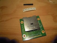
 Where did you get this SD card adapter board? Is it a MIDIbox thing or a regular commercial product?
 -
Well, for starters, you have the two SID audio buffer transistors (looks like they're called T1L and T1R) inserted in opposite ways, and the board around the top one looks discolored... To make things more confusing, I believe it is the case that transistors made in Europe have their pins arranged opposite from those in America. Check the datasheet for the transistors you're using and then insert the transistor according to the schematics for the SID module (or sammichSID board). I'm not absolutely sure, but from the traces here it looks like that would be the top hole of the three for each, which means the little symbol on the board corresponds to a European transistor. Since the top one looks like it has the board discoloration around it, my guess is that one's backwards, and therefore that you're using European transistors (that are supposed to correspond to the symbol on the board).
-
I already have +-5V power rails in my build, so how about this: Output of DAC goes through 10uf coupling capacitor, becomes -2.5 to 2.5 volts. Run this through unity-gain buffer made from normal non-rail-to-rail op-amp powered from +-5 volts. I've been experimenting with the LF412 op-amp and it clips at +-4.17 volts when powered from +-5, so that should be enough. Does this sound good? Also, do the sample-and-hold op-amps for the DAC need to go rail-to-rail? If so, I would need to make IC3 and IC5 on the MBHP_OPL3 board TLV2774 rail-to-rail op-amps powered from +5 volts, and then make IC6 a normal op-amp like LF347 powered from +-5 volts. And somehow insert the coupling capacitors between the two...
-
Is it possible to power the analog portion of the OPL3 module from +5 / -5 volts instead of +12 / -12 volts? The +5V power to the YMF262 and DACs would of course be unchanged.
-
Thank you, I thought it was something like that. I have been testing with 6581s (less to replace if I break something). In our build there are external audio attenuators on each SID that we can hook up to an envelope in the modulation matrix, though that will change the volume of the whole SID. As far as learning to love the "imperfections", there's also digitally controlled feedback loops to enhance the growly filters and digitally switchable filter capacitors (the idea from ) to have even finer control over the distortion. Setting the filter to band-pass and turning up the feedback and the resonance creates an oscillator, with the cutoff controlling its frequency; setting up feedback between two SIDs and changing the filter characteristics of the second makes the two resulting oscillators interfere, creating all kinds of crazy full-analog sounds. I just got the capacitor-switching working yesterday; we'll put up a video soon. :)
-
Since the beginning of testing the SID circuits for my build, starting from just the standard SID module on a breadboard, whenever I release a note each voice of the SID keeps playing a very quiet organ-like sound at the pitch it was last played at. If I set ADSR all to zero, then I can effectively play this noise with the keyboard. The noise stops entirely if the voices are sent to the filter and then all filter modes are turned off, confirming that this is an internal thing. I don't remember offhand whether the noise also stops if I turn off all waveforms, and I haven't tried setting the frequency to zero after setting the gate bit to zero (because then Release wouldn't work). I don't hear this noise in any of the MIDIbox SID demos. I'm using my own code to drive the SIDs (from the LPC17 core), so there might be some software optimization in the standard firmware that reduces this that I don't know about. Has anyone had any luck getting rid of this noise?
-
Check the current pass-through capabilities of the shift register you're using (i.e. look at the datasheet). It may be high enough to drive it directly. It also depends on what value resistor you put in series with each LED (or on the DOUT board), which controls the brightness of the LEDs: calculate the current using I = V/R. Each LED wants about 20-25 mA of current for full brightness (though check your LED's datasheet if it's blue or white or some other less-ordinary type). If you will need more current than the shift register can provide, you need some sort of transistor. I think (but I don't have formal training) that your circuit would work. The BLM I'm making involves driving 64+ LEDs at full brightness (~2 amps) from one DOUT pin, and a friend who's an electrical engineering professor suggested I use a P-channel MOSFET instead of an NPN transistor like in your design (which I had suggested to him). With a MOSFET, he said, you wouldn't need a resistor between the shift register and it; and I believe it (ideally) doesn't take any current to operate when it is either fully off or fully on, only when transitioning. But if you only need to drive 4 LEDs, your circuit is probably sufficient, and I think you could use an ordinary TO-92 package transistor. Try it on a breadboard and see! I think the worst that could happen is that you fry the transistor, and they're only a few cents. Also, I heard that you're not supposed to put LEDs directly in parallel; if one takes slightly more current than the others due to manufacturing irregularities, it will get hotter faster than the others, and as it gets hotter it will take even more current, and this continues up to a point; but then the one LED is running hotter than the rest and will have a shorter lifespan. I think (but I'm not positive) that putting LED-resistor pairs in parallel solves this problem (that is, use one resistor for each LED rather than one for all four).
-
Thanks again! Just one more question about project.sym (which is AWESOME, by the way; I always knew something like this existed somewhere for every program, but actually seeing it in plain text is totally cool!): does the linker always put variables next to each other with no empty space in between? That is, can I find the size of any variable by subtracting its index from the next index above it?
-
Thank you! So even though the LPC1769 treats the second 32k block as two 16k blocks, they have contiguous addresses, so I can have an array (in this case about 19k) going between the two? Also, is there anything else by default (e.g. MIDI input buffers or something) in this 32k that I should leave room for, or can I use it all? Finally, out of curiosity, where (within the MIOS32 trunk) are these sections defined? I've poked around the source a bit but I haven't seen anything like a memory map. After a bit more poking around, I found etc/ld/LPC17xx/LPC1769.ld . Not that I understand one bit of it... :wink: