

Sauraen
-
Posts
460 -
Joined
-
Last visited
-
Days Won
26
Content Type
Profiles
Forums
Blogs
Gallery
Everything posted by Sauraen
-
Anyone have any ideas why this is happening or what I should do? New computer, Ubuntu 13.04 AMD64. sudo apt-get install lib32gmp3-dev Reading package lists... Done Building dependency tree Reading state information... Done Some packages could not be installed. This may mean that you have requested an impossible situation or if you are using the unstable distribution that some required packages have not yet been created or been moved out of Incoming. The following information may help to resolve the situation: The following packages have unmet dependencies: lib32gmp3-dev : Depends: libgmp3-dev (= 2:4.3.2+dfsg-1ubuntu1) but 2:5.0.5+dfsg-2ubuntu3 is to be installed Depends: lib32gmpxx4 (= 2:4.3.2+dfsg-1ubuntu1) but 2:5.0.5+dfsg-2ubuntu3 is to be installed E: Unable to correct problems, you have held broken packages. Does this mean the version of libgmp3-dev is too new? How do I downgrade it?
-
Mighty No. 9 - "Backported" (Main Theme) (Remix)
Sauraen replied to Sauraen's topic in Songs & Sounds
Thanks! -
Unfortunately, this was not created with ASIDITY. :smile:
-
I would love it if they paid me $20,000, but I don't think that's going to happen. Well okay then! $60 it is and if I ever do make $20,000 from using it, I'll be happy to send an extra $200 the way of Cockos.
-
Well, I'm going to pay the non-discounted price, because I will be making money from my use of it (hopefully a few times the cost of the program), and that's commercial use. But that's still a fraction of what I was expecting to have to pay for a good program. Anyway, I get the point, price is not always correlated with value.
-
Assuming you want 3 color LEDs under each pot, that's 60 x 3 x 15 mA per LED = 2.7 A, much more than even high-power USB can supply. Probably the easiest way to do this, since your box wouldn't have any analog audio components in it, would be to get a cheap 5VDC 4A switching PSU (like this one). LPC17 definitely, if you want to do any tweaking of the code. Do you want to use actual analog potentiometers and AINSER64 or digital encoders? By the way, your Protodeck project looks awesome!
-
The short answer is no, in so far as the Wurlitzer EP is an actual acoustic instrument that's electrically amplified; the keys are connected to levers that hit metal bars, and then there's pickups over the bars to create the sound. The MBNG requires that each key have at least one electrical switch that is connected or disconnected when the key is pressed, like on fully-electronic keyboards. Unless you want to add some sort of switches to all the keys, which is possible but not very feasible. On the other hand, you only paid $100 TOTAL for all seven? Do they work? Do you want to sell one?
-
Well, that seems to be quite a consensus. I'll give it a try. But isn't it, like... too inexpensive? ;)
-
There's a chance that in a couple months, I will be commissioned to write the soundtrack for an indie film. If this works out, I will need to upgrade my music production software immediately; if not, the upgrade will still happen but much later. I work primarily with VSTIs that imitate real instruments (EastWest Complete Composers Collection), and only secondarily with electronic sounds and hardware (e.g. MIDIbox). I've been using Sibelius 5 for a few years and I love it, but in trying to make a professional-quality instrumental with it I've found out that I need automation (at least for volume) and EQ, which Sibelius doesn't offer; so I had to export audio track-by-track into Audacity and do the levelling and EQ work manually afterwards, which was a pain. I want to be able to, all within one program, go from writing in notes (hopefully in an intuitive manner and not painstakingly clicking one-by-one on a piano roll) to hearing the final mix playing in real time. EQ, reverb, the works; automation of any VST parameter; an intuitive way of working with the velocity and CC layers of a MIDI track. And it absolutely has to be a 64-bit program (Windows), since my new computer has 32 GB of RAM specifically for this purpose. As far as price, if I get this commission I'll have a little money to spend on it, but I'd still rather it be less than $1000. My experiences with other DAWs are the following: Tried FL studio; couldn't figure out the simplest things: how to get notes into a track, how to connect the output of a MIDI track to a VST, how to connect the output of a VST to an audio bus like Master... Tried Pro Tools; it always BSOD'd my computer within five seconds of startup.
-
On the one hand, as Shuriken said, it looks pretty difficult, and you'd be dealing with sampled audio so you'd need an entirely separate ADC and probably dedicated processor to put what you're sampling into its RAM. On the other hand, if it makes no distinction between sample operators and FM operators, it sounds like you can FM-modulate the sample, which is pretty advanced. Add in a live sampling capability and this could be a pretty crazy machine. Overall, I think this thread belongs in the "Pipe Dreams" section of the forum. :rofl:
-
As far as the SPI connection, it's easy, connect it to J19 on the LPC17 core the same way that the DIN/DOUT modules are connected to J8/9. J19:SC - AD5235:CLK J19:SO - AD5235:SDI J19:RC1 - AD5235:#CS And if you want the LPC17 to be able to read data from the digipot: J19:SI - AD5235:SDO If you have a bunch of dpots connected, you have two options: If you want one frame of your synth's operation to refresh the values in all of them (with different values of course): chain their SDI and SDOs (i.e. make the SDO of the first go into the SDI of the second, etc., and the SDO of the last into J19:SI). Connect all their #CSes and CLKs together. If you want to only refresh one at a time, connect their CLKs, SDIs, and SDOs together, and connect each of their #CSes to a different IO pin on the LPC17. Examples include: J19:RC2, all of J10, all of J5A and J5B if you're not using them, all of J28... You will of course have to write the module driver for them one way or the other, but that's not very difficult; when you get there you can use the same code I used to control the OPL3 from LPC17.
-
Problem: For this to work, you have to just replace the potentiometer from the original circuit with the appropriate pins of your digipot (let's forget about the 250K / 500K issue for now and assume you wanted a 250K pot to start with). However, if I'm reading the datasheet for AD5235 correctly, you can only apply a voltage to its pot pins between that chip's Vss and Vcc, which can't be farther apart than 0 and 5 volts. Therefore, as far as I can tell, you can't use this chip with the +15 / -15 volt MB808 board. It will not work to "amplify" the resistor with a 3x op-amp circuit (or 6x with a constant subtracted to get the full range); an op-amp circuit does not have the same electrical characteristics at all as a resistor. For starters, a resistor conducts signals (not to mention current) in both directions, while an op-amp only conducts signals in one direction and is designed to conduct almost no current. As far as I can tell, you have two options: first, find a digipot chip that can itself be supplied from +/- 15 v (this may not exist, I've looked for similar things for voltage DACs to no avail). Second, since that little segment of the original MB808 circuit that includes the pot, capacitor, resistor, and single op-amp is just an amplifier with a capacitor across the feedback with a variable effect, you could replace that chunk with a VCA circuit, add the capacitor in an appropriate spot (you'd have to experiment), and control that with your digipot. Edit: You may have another option. Do a search for "voltage controlled resistor". Looks like you can use a JFET as a resistor; one article recommends PN4119A; buy a few, plunk them in and see what happens. Worst case scenario you fry some transistors; I don't think you'd even fry the op-amp. Connect the two ends of your digipot to +5 and 0, and the wiper to the gate of the JFET; then connect the source and drain of the JFET in place of the resistor, trying to match the polarity of that capacitor next to it. One problem is that the JFET has a resistance 1/100th what you need, but you shouldn't have to chain 100 of them, there should be a way to modify the values of the capacitor and resistor in the MB808 circuit to get the range of decay times about the same.
-
I didn't know such a thing as a "digipot" existed. Do they work? Are they reliable? If so, then sure; you might even be able to use existing MB808 audio boards, with a veroboard layer either above or below them and pins through to the potentiometer solder connections. Also, video please once you make the kick!
-
First, I should let you know that I'm not near my equipment for the next three weeks, so I can't try anything and I don't think I have the most updated version of my code. Once I get back, it shouldn't theoretically take long for me to get the OPL3 module entirely working, but knowing my previous inaccuracies in terms of estimating time, I can't give a number. Bug me here if you have questions and I'll spend more time on it. My whole synth won't be done for another year at least, but you won't be using the sequencer or front panel or SIDs so those don't matter. My code is functional enough to get 18-voice polyphony out of the OPL3, but not enough to properly control all the parameters. The key issue seems to be that some but not all of the parameters seem to be either bitflipped or reversed from how they would seem they should be. For instance, when my code calculates the frequency and sends that, it sounds correct (and either of the above conditions would be audibly wrong). However, the ADSR parameters seem to count in reverse (i.e. sending 0xF gives you a value of 0 and 0x0 of 15), and some of the bit flags seem to be flipped as well. Part of the difficulty was that I didn't have any device, besides the front panel of ASIDITY itself, which had enough knobs to control all the parameters of one voice, and the front panel wasn't near done. As far as hardware, you need an LPC17 core and processor with the whole board populated, and you need to make a circuit on veroboard that contains a single 74HC595 output shift register, to convert an SPI signal from the core to the D0-D7 pins of the OPL3. I personally also modified the analog portion of the OPL3 board to fit voltage requirements of my synth, but again that doesn't affect you--you can build it normally if you want. The pins are hooked up this way (ignore the colors, that's my own wires): J19: SC (GPIO0.15): Serial clock for shift register [purple, gray] RC1 (GPIO0.16): Shift register latch [black] SI (GPIO0.17) (no buffer): [green] SO (GPIO0.18): Serial data for shift register [blue] RC2 (GPIO0.21): OPL3 RS (IC#, i.e. Reset) [white] J28: SCLK(GPIO2.11): OPL3 A0 [purple, gray] WS (GPIO2.12): OPL3 A1 [black] SDA (GPIO2.13): OPL3 CS/WR [blue] MCLK(GPIO4.29): You could put the pins that I have on J28 on J10 or elsewhere if you want; my build had J10 all used already. Edit: Oh, and I assume you realize that anything higher-level than the module driver, i.e. the application, is completely different for me as for you, and you'll have to write that how you want yourself. This will just get you an API to control all the parameters of the OPL3--which you could write a small application connecting them all to CCs and then plug it into a DAW for instance--but not a complete synth like MBFM with LFOs, extra EGs, etc.
-
If you say so! It's not done, so I'll just tease you with the header: // $Id: opl3.h $ /* * Header file for MBHP_OPL3 module driver * * TODO: Make the pins specified to only work for LPC17! * * ========================================================================== * * Copyright © 2012 Sauraen (sauraen@gmail.com) * Licensed for personal non-commercial use only. * All other rights reserved. * * Partially based on SID module driver from: * * Copyright © 2008 Thorsten Klose (tk@midibox.org) * Licensed for personal non-commercial use only. * All other rights reserved. * * ========================================================================== */ #ifndef _OPL3_H #define _OPL3_H #ifdef __cplusplus extern "C" { #endif /* OPL3 Programming Information ^^^^^^^^^^^^^^^^^^^^^^^^^^^^ To simplify programming an interface for this driver, the operator-channel mapping used externally here has been made much more obvious than the way they are connected inside the actual OPL3. This driver does the conversion. OPL3 has 36 operators, and up to 20 channels (in 2-op percussion mode). Six pairs of channels may be merged together individually, to make up to 6 four- voice channels. The operator and channel numbers are rearranged in this driver so that the connected ones are always next to each other. ==================================+==================================+ Operators you use | Actual operators in OPL3 | Chan | 2-Op Mode | 4-Op Mode |Chan | 2-Op Mode | 4-Op Mode | =====+===========+================+=====+===========+================+ 0 | 0, 1 | 0, 1, 2, 3 | 0 | 0, 3 | 0, 3, 6, 9 | 1 | 2, 3 | -- | 3 | 6, 9 | -- | 2 | 4, 5 | 4, 5, 6, 7 | 1 | 1, 4 | 1, 4, 7, 10 | 3 | 6, 7 | -- | 4 | 7, 10 | -- | 4 | 8, 9 | 8, 9, 10, 11 | 2 | 2, 5 | 2, 5, 8, 11 | 5 | 10, 11 | -- | 5 | 8, 11 | -- | 6 | 12, 13 | 12, 13, 14, 15 | 9 | 18, 21 | 18, 21, 24, 27 | 7 | 14, 15 | -- | 12 | 24, 27 | -- | 8 | 16, 17 | 16, 17, 18, 19 | 10 | 19, 22 | 19, 22, 25, 28 | 9 | 18, 19 | -- | 13 | 25, 28 | -- | 10 | 20, 21 | 20, 21, 22, 23 | 11 | 20, 23 | 20, 23, 26, 29 | 11 | 22, 23 | -- | 14 | 26, 29 | -- | -----+-----------+----------------+-----+-----------+----------------+ 12 | 24, 25 | -- | 15 | 30, 33 | -- | 13 | 26, 27 | -- | 16 | 31, 34 | -- | 14 | 28, 29 | -- | 17 | 32, 35 | -- | -----+-----------+----------------+-----+-----------+----------------+ 15 | 30, 31 | 30+31: BD | 6 | 12, 15 | 12+15: BD | 16 | 32, 33 | 32: HH 33: SD | 7 | 13, 16 | 13: HH 16: SD | 17 | 34, 35 | 34: TT 35: CY | 8 | 14, 17 | 14: TT 17: CY | =====+===========+================+=====+===========+================+ */ ///////////////////////////////////////////////////////////////////////////// // Global definitions ///////////////////////////////////////////////////////////////////////////// // pin mapping for GPIO pins #ifndef OPL3_SCLK_PORT #define OPL3_SCLK_PORT 2 #endif #ifndef OPL3_SCLK_PIN #define OPL3_SCLK_PIN 3 // J10:D1; shared with SID module SCLK #endif #ifndef OPL3_DAT_PORT #define OPL3_DAT_PORT 2 #endif #ifndef OPL3_DAT_PIN #define OPL3_DAT_PIN 8 // J10:D6; shared with SID module DAT6 #endif #ifndef OPL3_SRLAT_PORT #define OPL3_SRLAT_PORT 0 #endif #ifndef OPL3_SRLAT_PIN #define OPL3_SRLAT_PIN 17 // J19:S1 #endif #ifndef OPL3_A0_PORT #define OPL3_A0_PORT 0 #endif #ifndef OPL3_A0_PIN #define OPL3_A0_PIN 15 // J19:SC #endif #ifndef OPL3_A1_PORT #define OPL3_A1_PORT 0 #endif #ifndef OPL3_A1_PIN #define OPL3_A1_PIN 16 // J19:RC1 #endif #ifndef OPL3_WR_PORT #define OPL3_WR_PORT 0 #endif #ifndef OPL3_WR_PIN #define OPL3_WR_PIN 18 // J19:S0; connected to OPL3 WR# and CS# #endif #ifndef OPL3_RS_PORT #define OPL3_RS_PORT 0 #endif #ifndef OPL3_RS_PIN #define OPL3_RS_PIN 21 // J19:RC2 #endif ///////////////////////////////////////////////////////////////////////////// // Global Types ///////////////////////////////////////////////////////////////////////////// typedef union { u8 ALL[5]; struct { //Byte 0: 0x20 + operator offset u8 fmult:4; //Multiplier for channel frequency u8 ksr:1; //How much to scale amp EG with pitch u8 dosustain:1; //Whether to sustain the note while gate is held u8 vibrato:1; //Whether to use the frequency LFO u8 tremelo:1; //Whether to use the amplitude LFO //Byte 1: 0x40 + operator offset u8 volume:6; //Volume level of operator, or how much to have it affect the carrier (if it's a modulator) u8 ksl:2; //How much to scale volume with pitch //Byte 2: 0x60 + operator offset u8 decay:4; //Decay rate for amp EG u8 attack:4; //Attack rate for amp EG //Byte 3: 0x80 + operator offset u8 release:4; //Release rate for amp EG u8 sustain:4; //Sustain level for amp EG; only held at this value after decay if dosustain == 1, otherwise, immediately goes to release //Byte 4: 0xF0 + operator offset u8 waveform:3; //Waveform select u8 dummy:5; //Bits ignored by OPL3 }; } opl3_operator_t; typedef union { u8 ALL[3]; struct { //Byte 0: 0xA0 + channel offset u8 fnum_low; //Lower 8 bits of frequency number //Byte 1: 0xB0 + operator offset u8 fnum_high:2; //Higher 2 bits of frequency number u8 block:3; //Block number u8 keyon:1; //Key on (gate) u8 dummy:2; //Bits ignored by OPL3 //Byte 2: 0xC0 + operator offset u8 synthtype:1; //Algorithm selection u8 feedback:3; //Feedback; only works in some operators (one per channel) u8 left:1; //Whether to send this signal to output 1 (A) (left) u8 right:1; //Whether to send this signal to output 2 (B) (right) u8 out3:1; //Whether to send this signal to output 3 © u8 out4:1; //Whether to send this signal to output 4 (D) }; } opl3_channel_t; typedef union { u8 ALL[4]; struct { //Byte 0: 0x05 only in higher register set u8 opl3mode:1; //Whether to act like an OPL3 as opposed to OPL2 u8 dummy:7; //Bits ignored by OPL3 //Byte 1: 0x08 only in lower register set u8 dummy2:6; //Bits ignored by OPL3 u8 notesel:1; //Which bits of the frequency register to use to determine where to break up the keyboard for key scaling u8 csw:1; //Composite sine wave mode; may not be supported by OPL3 (only OPL2), and nobody on the Internet knows how to use it even there //Byte 2: 0xBD only in lower register set u8 hh:1; //If in percussion mode, play hi-hat (operator 32 in this driver) u8 cy:1; //If in percussion mode, play cymbal (operator 35 in this driver) u8 tt:1; //If in percussion mode, play tom-tom (operator 34 in this driver) u8 sd:1; //If in percussion mode, play snare (operator 33 in this driver) u8 bd:1; //If in percussion mode, play bass drum (operators 30 and 31 in this driver) u8 percussion:1; //Percussion mode u8 vibratodepth:1; //How deep the vibrato (frequency LFO) should be u8 tremelodepth:1; //How deep the tremelo (amplitude LFO) should be //Byte 3: 0x04 only in higher register set u8 fourop; //Lower six bits are whether four-op mode is enabled for six channels which support them }; } opl3_chip_t; ///////////////////////////////////////////////////////////////////////////// // Export global variables ///////////////////////////////////////////////////////////////////////////// extern opl3_operator_t opl3_operators[36]; extern opl3_channel_t opl3_channels[18]; extern opl3_chip_t opl3_chip; ///////////////////////////////////////////////////////////////////////////// // Prototypes ///////////////////////////////////////////////////////////////////////////// // Call this when setting up the microcontroller. Sets up GPIO pins, internals, // calls OPL3_Reset(). extern s32 OPL3_Init(void); // Sends reset signal to OPL3 and then refreshes it with current data. // Why a synth would have to use this except in initialization I don't know. // (It's automatically called by OPL3_Init().) extern s32 OPL3_Reset(void); // Refreshes all OPL3 registers. Call this after your app is done initializing. extern s32 OPL3_RefreshAll(void); // Call this after every control refresh. Refreshes any OPL3 registers that have // changed since last time. extern s32 OPL3_OnFrame(void); // Convenience functions for interacting with OPL3 // You MUST use these functions to write data to OPL3 or the OPL3 will not be // refreshed with the data on the next frame! //For an operator extern s32 OPL3_SetFMult(u8 op, u8 value); extern s32 OPL3_SetWaveform(u8 op, u8 value); extern s32 OPL3_SetVibrato(u8 op, u8 value); extern s32 OPL3_SetVolume(u8 op, u8 value); extern s32 OPL3_SetTremelo(u8 op, u8 value); extern s32 OPL3_SetKSL(u8 op, u8 value); extern s32 OPL3_SetAttack(u8 op, u8 value); extern s32 OPL3_SetDecay(u8 op, u8 value); extern s32 OPL3_DoSustain(u8 op, u8 value); extern s32 OPL3_SetSustain(u8 op, u8 value); extern s32 OPL3_SetRelease(u8 op, u8 value); extern s32 OPL3_SetKSR(u8 op, u8 value); //For a channel extern s32 OPL3_Gate(u8 chan, u8 value); extern s32 OPL3_SetFrequency(u8 chan, u16 fnum, u8 block); extern s32 OPL3_SetFeedback(u8 chan, u8 value); extern s32 OPL3_SetAlgorithm(u8 chan, u8 value); extern s32 OPL3_OutLeft(u8 chan, u8 value); extern s32 OPL3_OutRight(u8 chan, u8 value); extern s32 OPL3_Out3(u8 chan, u8 value); extern s32 OPL3_Out4(u8 chan, u8 value); extern s32 OPL3_SetFourOp(u8 chan, u8 value); //For the whole OPL3 extern s32 OPL3_SetOpl3Mode(u8 value); extern s32 OPL3_SetNoteSel(u8 value); extern s32 OPL3_SetCSW(u8 value); extern s32 OPL3_SetVibratoDepth(u8 value); extern s32 OPL3_SetTremeloDepth(u8 value); extern s32 OPL3_SetPercussionMode(u8 value); extern s32 OPL3_TriggerBD(u8 value); extern s32 OPL3_TriggerSD(u8 value); extern s32 OPL3_TriggerTT(u8 value); extern s32 OPL3_TriggerHH(u8 value); extern s32 OPL3_TriggerCY(u8 value); //Convenience functions for reading extern u8 OPL3_IsChannel4Op(u8 chan); extern u8 OPL3_IsOperatorCarrier(u8 op); #ifdef __cplusplus } #endif #endif /* _SIDFEEDBACK_H */
-
Of course!
-
I've wanted to do something like this too, partly to increase my understanding of analog electronics. This is what I would recommend: Pick a voice with a distinctive sound (e.g. snare drum), and build just that voice on a breadboard from the schematics. If you have a nice fully-stocked electronics workshop, this probably would only take an hour or two. Hook up the trigger to a microswitch and the audio output to a mixer. See if it works. Twiddle the knobs and enjoy. Buy and build an LPC17 core board, and buy a few two-channel-output SPI-input voltage DACs. Hook them up to SPI on the LPC17 and write a small driver program that lets you control their voltage output with CCs or something. Once you can reliably control the voltage output of the DACs, find a circuit on the Internet that performs the same function as each portion of the 808 voice that includes a potentiometer, except voltage controlled. For instance, if one of the segments of the snare drum circuit is a low-pass filter with adjustable cutoff, find a simple VCF design online, match the parameters, and hook up the voltage input to one of the outputs of your DAC. Replace that segment of the original 808 circuit with the voltage-controlled one. Repeat for all parameters of the voice, or even parameters that are fixed in the original design for more control. Presto! You just made yourself a digitally-controlled analog drum synth!
-
Gotta love dat Electribe!
-
We've been planning to do another video for a long time, but nothing that we would show off is entirely working. E.g. four of eight SIDs are working fine, two are working almost fine, and two not at all (but it's not the SIDs themselves, it's my custom boards for them). I got the OPL3 module working, but again, it's only mostly working--some of the parameters seem to be backwards, and I don't have an already-existing control surface with enough knobs to control all of them. In both cases, what it can do is just play those sound chips in a very vanilla way; without the front panel all done, it's useless to try to run them off the version of the OS that includes the giant modulation matrix and all, because there's no way to control it. But thank you! Hopefully I'll get the rest of the kinks with the front panel straightened out in the next couple weeks, and then make a video just showing that.
-
The front panel is finally working! It's not entirely done--we have to get the LED displays and LCDs working, but the matrix works!
-
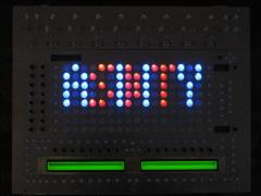
From the album: MIDIbox ASIDITY
The front panel is finally working! It's not entirely done--we have to get the LED displays and LCDs working, but the matrix works! -
Just have to attach some DIN wires and the front panel will be done! (Except debugging, of course!)
-
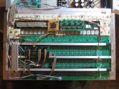
From the album: MIDIbox ASIDITY
Only thing left is to connect some DIN wires, and then it should work. Of course, we all know how well things work the first time... -
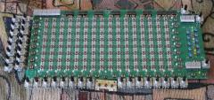
From the album: MIDIbox ASIDITY
Can't wait until it's powered! -
 Ha ha, thanks!
