

Sauraen
-
Posts
460 -
Joined
-
Last visited
-
Days Won
26
Content Type
Profiles
Forums
Blogs
Gallery
Everything posted by Sauraen
-
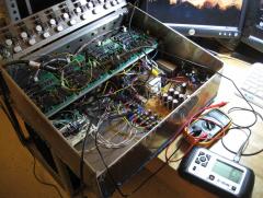
From the album: MIDIbox ASIDITY
Two of four SID boards seem to work fine; two don't make sound on the output of the SIDs. I'm on it! -
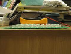
Ha ha, I did a test 3x2 matrix on a breadboard with these LEDs, and looking directly down into them is actually uncomfortable. But it's dispersed in all directions by the buttons, so it shouldn't be too bad. :)
-
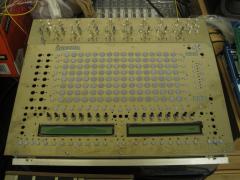
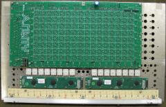
We finished soldering the front panel circuit board today and did a preliminary assembly of the front panel! Each of the larger buttons has red, yellow, green, and blue ultrabright LEDs under it; the total light power of the front panel will be about that of a 40 watt light bulb. Can't wait for once it's wired up...
-
From the album: MIDIbox ASIDITY
-
From the album: MIDIbox ASIDITY
-
From the album: MIDIbox ASIDITY
Partially assembled, of course. -
From the album: MIDIbox ASIDITY
-
MIDIbox ASIDITY Front Panel board almost complete!
Sauraen posted a gallery image in MIDIbox Gallery
From the album: MIDIbox ASIDITY
-
From the album: MIDIbox ASIDITY
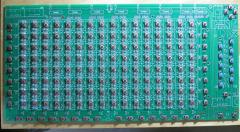
Red Yellow Green Blue, 8 rows x 16 cols! -
Okay, so they really mean that it won't work on signals above 5KHz! What's the use of an op-amp that can't even work on audio-frequency signals (let alone data)?! But sure, I'll buy new ones. It does sound kinda cool, though--sort of like twelve 6581 SIDs with their filters and feedback going. Maybe I'll put up a video with these while I wait for new ones to arrive.
-
I'm not exactly sure what I fixed, but I am now getting sound out of the OPL3. There's still a weird bug that the values for some--but not all--registers of the OPL3 have to be sent bit-flipped, or rather, that it interprets the data to be the opposite values for each pin as what I send, but only for certain registers (e.g. ADSR and volume, but my tuning system works fine). But I can work around that in software. However, I cannot get a sine wave out of the OPL3. I know I am only triggering one channel at a time (because I can trigger twelve or more of them independently); I know it's not that I have the waveshape set wrong, since setting it to other values gives me something that sounds even less like a sine wave; and it's not being FM modulated by the other operator because the other operator's volume and envelope are silent and it's set to the non-FM mode. So I don't think it's a software problem, which led me to the hardware. Since for my synth I don't have a +/- 12V power supply and I didn't want to add one just for the OPL3, I changed the design for the board: the first two op-amp packages I replaced with rail-to-rail op-amps like in the sammichFM and gave them 0/5V, and then kept the last one as a TL074 and gave it +/-5V. (This by itself is not the problem; the chips are getting the right voltages and there are no shorts). In between the buffer immediately after the YAC512 and the second (final) one, I added an electrolytic capacitor in series and then a resistor to ground, to take the waveform from being centered at 2.5V to 0V. I'm pretty sure all this is working fine, since the sound does not get more distorted as the volume is turned up inside the OPL3. I started thinking that maybe the op-amps I used, TLV2244, actually weren't quite rail-to-rail and therefore were clipping the signals in the DAC portion (sample-and-hold or whatever it is) of the YAC circuits (not the audio out portion). I didn't use the OPA4348 from the sammichFM because they are only available as SMD. But the datasheet for the TLV2244 shows that it is legitimately rail-to-rail; the only significant difference between the datasheets is the bandwidth. The OPA4348 is 1MHz and the TLV2244 is 5KHz. Could this be the problem?
-
OPL voltage problems (fixed) -> now PSU voltage problem
Sauraen replied to Marxon's topic in Testing/Troubleshooting
Don't give up on your OPL3 yet--though they're not very expensive on eBay. I haven't followed all your earlier posts, but I did notice something: - The OPL3 board power LED is connected directly to J1 (well, through a resistor). Whenever the board is receiving +5V, that LED will be on; if it's going on a second after you power on, something is shorting/drawing too much current for 1 second. The LED should light dimly even if the board only has +3.8V. If the YMF262/YAC512s are getting +5V/Gnd like in your first example, the LED will be on. If not, you can start there. If you have a multimeter with this capability, you can also try hooking it up in "current" mode and wiring it in series with J1, to see how much current the OPL3 board is drawing. According to the datasheet, the YMF262 draws 10 mA, and each of the YAC512s should be about the same. If the +5V rail is being loaded by the OPL3 board by more than 100 mA, there's some short, internal or external. Good luck! -
Hi TK, I'm running MIOS Studio 2.3.0 on Ubuntu 10.04, I apologize if this has been fixed in a later version. When I'm debugging a program, I leave the LPC17 on and connected via USB and I leave MIOS Studio open. I change some code, recompile, and then want to upload the new version. I discovered during my recent debugging session that clicking Browse and selecting the same file does not cause MIOS Studio to send the new, recompiled project.hex, but the same one it just sent. The only way I can get it to reload that file is by dropping down the file path box and selecting a different project.hex from a different project, and then going back to the original one. Can you make it reload project.hex from disk every time you click Send? Thanks, Sauraen
-
Nope--I saw that one in advance. :smile: I have #IC connected to J19:RC2, which goes through the buffer on the LPC17 board, and that pin measures at 4.95 volts during operation. Besides, if it was stuck in reset, it wouldn't be making any noise at all, I would think. But thanks for taking the time to think of that!
-
I've been working on a LPC17 driver for the OPL3 module to be used in There is a 595 shift register connected to J19 via SPI, and the other control pins on the OPL3 module are connected to J28 (reconfigured as GPIO). After squashing a number of other bugs, it appears that the OPL3 board is receiving the right data; whenever I pause execution and measure the voltages on its input pins (both the outputs of the shift register and the pins wired directly to the core), they are all correct. But the OPL3 seems to only be sporadically receiving the data. My program simply sends messages to set up one channel and its operators, and toggle the note on and off. What this results in is no sound for a while; then eventually the correct note turning on but not off; then multiple new copies of it (i.e. in different channels) turning on, out of phase with each other and sometimes not exactly the right frequency; and this continues indefinitely, with the chip making dubstep-like noises. Resetting the chip (via the reset line) does not stop the sound, but of course toggling the power does. I'm guessing that it is getting the data wrong for some reason, but intermittently, and it seems it has more problem with the address byte than the data byte! I tried adding several microseconds of delay between each segment of the write cycle in case it was a timing issue, but that has had no effect. Anyone have any idea what might be going on? Bad solder joints? I'm sort of at a loss.
-
From the album: MIDIbox ASIDITY
-
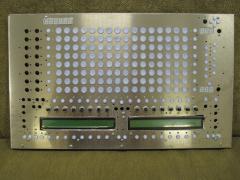
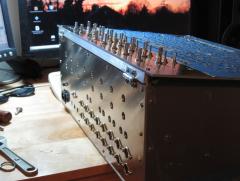
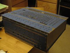
I had wanted to wait to show the case until it was all done, but after a day in the metal shop (back panel and top section of front panel), this photo was too good to pass up: By the way, there were too many bugs (and a mistake on the circuit board :bug: ) with the SID boards that I was not able to make a video last weekend.
-
From the album: MIDIbox ASIDITY
I had wanted to wait to show the case until it was all done, but after a day in the metal shop (back panel and top section of front panel), this photo was too good to pass up. :) -
We finished all the SIDFB boards! A video should be coming next weekend.
-
From the album: MIDIbox ASIDITY
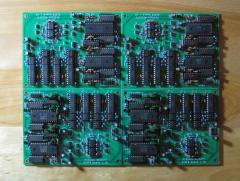
We finally finished soldering the SIDFB module boards! Each board contains two SIDs and their shift registers; a CD4052-based digitally-controlled filter capacitor switching circuit, 4 pairs capacitors per SID; LM1973-based digitally-controlled audio attenuators controlling feedback to self, feedback to other SID on the board, feedback to SID on next board, external audio output, and master L and R outputs; and the mixer circuit for all the feedback inputs (and external input) to each SID. The boards are custom-manufactured. The total across all four boards: eighty ICs, 248 resistors, 224 capacitors, 24 transistors, and sixty connectors, for a total of 2600 soldered holes! -
Basically. They're the four 20-pin chips towards the top left, LM1973s. Each LM1973 is basically three SPI-based 74-step DACs connected to three VCAs, and each channel requires a buffer op-amp. Each SID's audio output splits into six and then goes into six audio attenuator channels. The two channels that go to master L and R output are buffered at unity gain, while the three that are used for feedback and the one external output are at 3x gain. The "self" and "pair" (other SID on the board) feedback paths are built into the board, and the third path, the "next" path (to the corresponding chip on the next board), requires a wire where it says "3/NEXT". The whole idea came from the feedback knobs on the back of the MB6582, but digitally controlled (from the modulation matrix) and six times the number. :smile: Edit: The limiters on the feedback loops are not on this board, but attached directly to their control pots on the front panel, connected where it says "A LIM" and "B LIM".
-
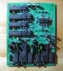
I finished one of the SIDFB boards today; I've been doing them in parallel, so the others will probably be done this weekend. 650 solder connections!
-
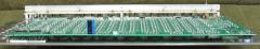
From the album: MIDIbox ASIDITY
This is one of the four SIDFB module boards that will be in MIDIbox ASIDITY. It contains two SIDs and their shift registers; a CD4052-based digitally-controlled filter capacitor switching circuit, 4 pairs capacitors per SID; LM1973-based digitally-controlled audio attenuators controlling feedback to self, feedback to other SID on the board, feedback to SID on next board, external audio output, and master L and R outputs; and the mixer circuit for all the feedback inputs (and external input) to each SID. The boards are custom-manufactured. The board contains twenty ICs, sixty-two resistors, fifty-six capacitors, six transistors, and fifteen connectors, for a total of 650 holes. -
Good luck! If all else fails, YAC512s are about $2 plus shipping on eBay.
-
I used those designs to make the feedback mixer circuits and main mixer in my build too. Just one thing bothers me about your first schematic: the main outs are inverted from the inputs, though the headphones are correct. :)
