

kpete
-
Posts
191 -
Joined
-
Last visited
-
Days Won
1
Content Type
Profiles
Forums
Blogs
Gallery
Everything posted by kpete
-
And your " u8 led_startstop = 14; " must be outside of any function. If it was inside a function then it can only be found and used by that function.
-
Strange startup behaviour for shift registers
kpete replied to latigid on's topic in Testing/Troubleshooting
This is one of the problems with using a serial interface to the Dout boards that don't have a power ON reset circuit or pin to hold the shift registers off. Most latching IC;s will power up in a random state and this is what you see before the Midibox starts scanning the Dio chain. For lights its usually not a problem but if you are driving electromagnets it can be problematic and something to consider in your design. Bringing up the power in stages with 2 power supplies works fine too. Pete -
Why not just buy the right board. They are cheep enough.
-
jjonas is right but doesn't give you enough information. It's been a long time that I have done this, but looking at the code this is what I see. In the mios_v1_9h.zip file are directories for each supported PIC. As you select your path, you will come to a "BURNER" directory. This is the one that must be programmed first. The hex file is something like "bootloader_v1_2b_pic18f4620.hex". It should contain all the CONFIG parameters needed to set the oscillator options in the PIC. After that you can then program the MIOS hex file for v1.9h which is in the "MIDI" directory and called something like "mios8_v1_9h_pic18f4620.hex". Note: programming this way gives and ID value of " #define PICID_DEVICE_ID 0x00 " If I am wrong, someone please respond. Pete
-
STM32F429 Timer triggered USART DMA transfer issue.
kpete replied to kostix's topic in Design Concepts
I don't know why your are so concerned about this 32us shift. I don't know why this is happening but 32us is 1 bit of the 30 bit (3 byte) Midi message which would take almost 1ms (0.96ms) for the entire message. A human can't tell the difference between 15ms from the time the key is pressed and the sound is generated. How do you expect a 32us delay to be a problem? What happens when you start using Midi over USB? The data might come faster as a buffered group but there is still a delay from the time the application starts sending it and the receiving device even sees it. It sounds like you are not using any of the Midibox software for your testing. Midibox uses a multi task operating system and I would think that if you tested it in this way it would not meet your expectations either. Respectfully Pete. -
From the first post I was wondering if you were using one of those synths that would send a Midi All Notes Off message for the last note rather than just a note off message. Your last post answered that question eptheca.
-
Having pin 10 connected to +5v should not be a problem but removing it won't hurt either. This is normally connected to a +V and is used to snub the voltage spiks that occur when the outputs of the ULN2803 are connected to relays. Since the outputs are connected to LED's, it is not needed.
-
Can I use J5 of PIC based core as a "LOGIC" input?
kpete replied to Rio's topic in Testing/Troubleshooting
Looking at the SP0256 spec you sent, this is a 5v device just like the PIC core. The LRQ output can drive 2 LS-TTL loads with a ZERO voltage of 0.5v and a ONE voltage at 2.5 volts. The PIC running on a 5 volt power supply can input a ZERO for anything less than 0.8v and a ONE for anything over 2.0 volts. So you can directly connect any of the SP0256 outputs to the PIC inputs without any issues. No resistor necessary. When you are debugging your code I would remove the SP0256 from the socket and make sure that your software has configured the TRIS registers correctly. You don't want to drive one of the SP0256 outputs with outputs from the PIC. You might blow up your SP0256 output pin if your PIC is configured wrong. -
Problems upgrading to full control surface (DIN, LED matrix)
kpete replied to oano's topic in MIDIbox SID
You have identified a big problem. You can clip out the current arrays and replace them with individual resistors if you want. You do need the bussed units. -
It's a Hobbico Wire Cutter. You can get it a Amazon for about $14 USD. Ebay also has them along with some Hobby stores. They are great for stranded wire larger that 26 AWG gauge wire but will nick the wires if solid copper. I have had some problems with wires breaking over time at the strip point when used on small gauge telephone wires. This was on an Organ with over 3000 soldered wires.
-
When power is applied to the PIC processor that has a boot loader in it, a SYSEX message is sent out the Midi Out port. It is f0 00 00 7e 40 01 f7 when the device ID is 0. If you have a simple LED, go ahead and stick the leads into the Midi Out connector on your core. When the unit is first powered up you should see the LED blink for a short period when this short message is sent out. If you don't see it flash the first time, then reverse the leads on the LED and cycle the power again going to the core. No flash indicates something is wrong. Either missing resistors, bad PIC or pick not programmed with MIOS or no +5v. You might even try looking at pin 1 of the PIC. It should have a resistor pullup on it. If it is missing it can cause the PIC to not run. If you have a display on your CORE it will show a message saying READY.
-
Mios8 and custom program : is it possible?
kpete replied to alexglvr's topic in MIDIbox Tools & MIOS Studio
Your software would have to run using the MIOS code that also includes the boot loader software, functions for Din & Dout and LCD functions. The Midi code that decodes the Midi commands is also part of this MIOS code. There is a skeleton code example that can be modified by you and compiled for your application needs. It is located at http://svnmios.midibox.org/listing.php?repname=svn.mios&path=%2Ftrunk%2Fapps%2Ftemplates%2Fasm_skeleton%2F Your code would have to work around all the code and variables used by MIOS. This skeleton code does this for you. I've used it for my Midi projects. -
Thanks for the update. And I understand the confusion with the port numbers.
-
So what Solved the final problem. Don't be shy. We all make dumb mistakes.
-
One question I have is why do you have no power on the Vdd pin and a voltage on the reference pin? Vdd should never be lower than the reference pin. Maybe this is why the part failed in the first place. Pete
-
The spec indicates that there is ESD protection on all pins. This tells me that there is a normally reverse biased diode between Vdd and all the pins on the chip. With the part only drawing 2 micro amps max., I would expect to see an open pin Vdd with a voltage due to any of the other pins having power on them, including the reference pin. The part is probably OK. Pete
-
 I am offering a low resistance path but I am also trying to make sure that the power surge doesn't get introduced directly into the ground of the logic. Under idea conditions the POWER + and - lines of all the DoutPower bds will go to the high current power supply that is floating and not grounded. There is a jumper on the board that can be shorted out that connects the Power - to the logic ground. The only jumper that should be connected is the first one in the Dout chain. This stops any of the high current surges from flowing thru the logic grounds which can upset the shift register states.
 -
From your description of your Dout modifications I had a good idea what you did. Good that you posted the pictures so others can relate to your change. I also did this for another project. I went ahead and took a picture of my layout to help indicate what I did. You did it the right way with having the Dout boards very close to each other. When I do mine, I will also put the Core CPU as close a possible to the Dout boards. As you can see I took all the power related + and - voltages to separate connections so they can be connected as needed in the specific application. There is a jumper that can be used to connect the power ground to the logic ground if not done elsewhere. I included the fly back connections as part of the power spike problems because when the coil is turned off, the current going back into the fly back diode is ~ 0.5amps for a short time, maybe 5-20us as a guess. My intent is to use my Core CPU as a driver only board (Midi In only). No Midi outputs. I was going to have the SAM's reed switches connections used by another board and the 2 systems wouldn't know about each others switch state. I was going to have Hauptwerk worry about this. I don't know if this will work or not. With your experience, maybe you could enlighten me? I haven't committed myself to using any specific Midi message at this time. Thought I would just start with Note-On/Off first since it is one of the more common used ones that might work with some of the other manufacturers such as Art???? or others. And I will certainly try it with the other cores since USB is the preferred interface. And no telling what John's problem was. A lot of the issues went away when he separated the SAM magnet wires from the reed switch wires that were used in a matrix configuration. And like you suggest, maybe some of the issues might be problem with magnetic coupling between SAMs rather than just wire coupling issues. Pete
-
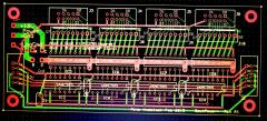
From the album: kpete
Layout of my Dout compatible board for driving SAM magnets. I'm calling it DoutPower+ -
-
-
Hi Mathis, I read through your posts in the other thread and with help from Thorsten you were able to get the NG software working with your SAM's. Congratulations are in place to you for going the extra effort to get this working. What is nice about your direction is that it is configurable to use any Midi command for control of the Sam's. It still might be overly complicated for some but we will wait and see. I don't know if you will have problems when things like a GENERAL CANCEL button is pressed and all of the stops are to turn off. You will have a separate script running a delay of 100ms for each SAM instructed to change states. I don't understand the NG software but know it is very flexible for projects like this. I will probably try it at some time just to see it work. I am much aware about only having 4 drivers being on at the same time. When I talk about isolating, it doesn't mean that the power grounds and logic grounds are completely isolated. Just that you now have a choice as to where they can be grounded together. Idealy it is at only one spot. What I don't want to happen is have any of the 8amp current spikes from each board passing thru the 10 pin ribbon cable connecting the logic. By doing this it will help in daisy chaining multiple boards. Hopefully 8 boards strung together is a goal for support of 128 Sam's. You may have already proven that 4 boards strung together works fine. How far are the Dout board from the STM32F4 and from each other? I have 3 STM32F4 boards and an order in for SmashTV for the PC boards. I was wondering what PC software you are using for your organ emulator? I think that John at would be interested in this conversation to.
-
I thought I would respond for Ray since he doesn't seem to be on line here very often. The Conn that he has doesn't have a matrix keyboard. It has about 5 whiskers/note that presses against 5 separate buss bars. He would be using the standard Din with 1 wire for each key. I have a Conn 830 that I have wired to a 256 input Midi board that I designed back in 2005. Its working now but my next project is getting the SAM's working with the Hauptwerk software that emulates a Wurlitzer 310. I designed a hardware board that looks like a Dout to Midibox with the ULN2803 chips substituted for the resistors. Difference being that the power and ground for the drivers is separated from logic shift registers. The output connectors are 8 pin headers that will handle the 0.5amp spikes rather than the 10-pin ribbon cable ones. I also plan to use the PIC based Core 8 board. Very simple interface. Intend to use Note ON to turn the stop ON and Note OFF to turn the stop OFF. Timing to pulse the SAM magnets with 100ms pulses will be done in software in the new .hex file. My boards should arrive in about 2 weeks. Pete
-
 They should be able to be daisy-chained just like the Dout boards. I just ordered 40 of these boards for my project and expect them to come in about 2 weeks later. Each board will support 16 SAM's. Only need 4 boards for the 51 SAM's on my gutted Conn console. A friend of mine bought my 1930's Wurlitzer console that he wants to control the 70 or so SAM's which need a - common driver where I need a + common driver board. That's why it can be configured for both chip types. Right now I want to use the older MidiBox core8 for the CPU since they are simple and cheep and they are 5 volt compatible. The plan right now is to use NoteOn/Off messages to turn the stops on and off. Will have a timer for each SAM and the core software will turn the drivers OFF after about 100-200ms of being turned ON. Will be using the consoles with Hauptwerk software in a PC. I hope to be able to control up to 256 outputs (128 Sam's on 8 DoutPower+ boards) from a single Core8 CPU. Will see if its possible when I start coding. The other problem I don't know about is how many of these boards will be able to be daisy-chained before having problems with noise. Maybe with careful layout of the grounds and power distribution there is a chance that 8 boards might work.
 -
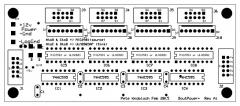
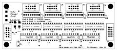 I created this PCB that is pin compatible with the Dout board but is designed for driving solenoids using different parts for either a Sink or Source mode drivers. Hoping to use these boards for driving Stop Action Magnets (SAM's) in my organ projects. It also allows me to isolate the logic grounds from the driver power grounds. It uses the MIC2981 or the ULN2803 driver chips. I used them because the pin configuration is similar and they seem to be available, at least for now. This board is larger than the Dout board from SmashTV.
 -
From the album: kpete
I created a PCB that is pin compatible with the Dout board but is designed for driving solenoids using different parts for either a Sink or Source mode drivers. Hoping to use these boards for driving Stop Action Magnets (SAM's) in my organ projects. It also allows me to isolate the logic grounds from the driver power grounds. It uses the MIC2981 or the ULN2803 driver chips. I used them because the pin configuration is similar and they seem to be available, at least for now. This board is larger than the Dout board from SmashTV.
