

jaytee
-
Posts
352 -
Joined
-
Last visited
-
Days Won
15
Content Type
Profiles
Forums
Blogs
Gallery
Posts posted by jaytee
-
-
On February 27, 2017 at 7:00 PM, Magus517707 said:
If you decide to go with the fan and you hear buzzing in your audio you may need to build an LC filter.
Link to post regarding fan noise on power railI had actually seen that link while researching my MB-6582 build. I was all prepared to build one of those filters, but then.....zero noise from the fan. I can hear no difference in my monitors between plugged and unplugged. So that's lucky.
If anyone is looking for a good fan for their MB-6582 build, I can personally recommend this one on Amazon. It's 5V only (although there is a 12V version), and requires very minor modification (it's a 3-wire fan, and the included hookup cable is way too long and stiff to look neat in the MB-6582 case; just snip the sensing wire and install a new connector at the end), but it adds no audible noise on the outputs, and physically speaking, is pretty whisper quiet too.
It's not the prettiest (kind of an ugly beige with a visible logo, definitely not the clear plastic and LED bling that I've seen on other MB6582s) and it's not the cheapest, but on a practical level, it seems to work well. I'll update here if I discover any problems or if it fails suddenly.
Also FWIW, I drilled some ventilation holes in my PT-10 case and installed the fan so that it's blowing all the hot air out of the case.
-
And here are the photos...
edit: they came out lower resolution than I meant when trying to get them to fit the forum's attachment limits. Here is a link to the full-resolution images: https://imgur.com/gallery/NUcHy
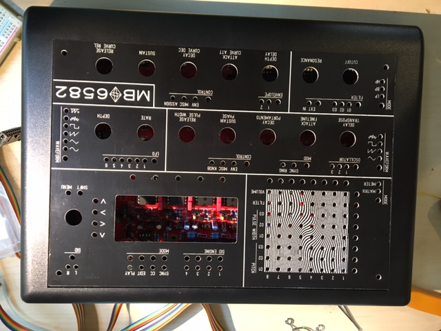
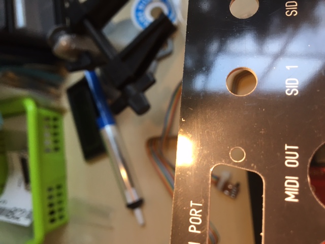
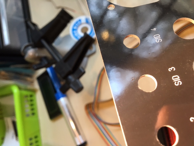
Front panel. Sorry, no idea why it's coming out upside-down. (Edit: they seem to be coming out right-side up on mobile....so I have no idea.)
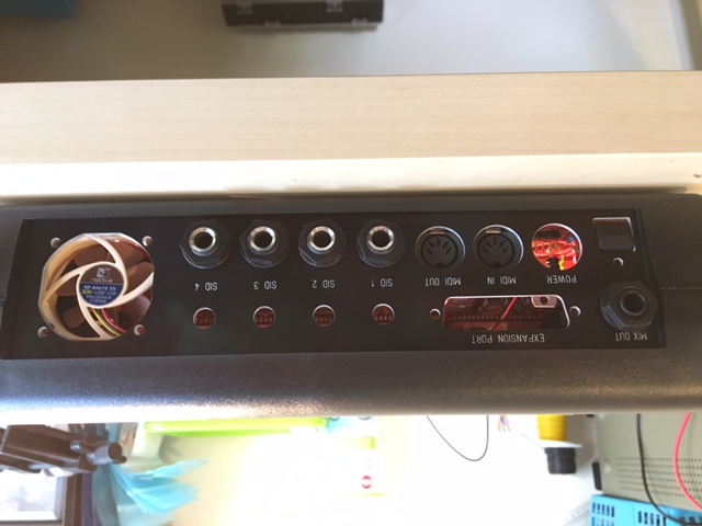
Rear panel, also upside-down. Please note, small mistake: the "MIX OUT" label that I added is very slightly obscured by the nut that attaches the new 1/4" jack. On the upside, the text is nice and level with "EXPANSION PORT." You could fix this by using a jack with a smaller nut, or by grinding/sanding/drilling the hole out to be slightly bigger, giving the jack a little wiggle room, or just by ignoring it as I plan to do. Edit: Checking it out again, it's not even obscuring it at all, it's just closer than is strictly aesthetically pleasing. Also, the jack I am using is just a Rean clone of whatever jacks are specified for the other four outs, just with solder tabs instead of PCB pins. I'm sure most 1/4" jacks will fit, but if you're worried, I can track down the exact part number.
Some scuffs from rubbing against the other panels during shipping. Looks worse in the picture than it is, imo. This is under my bench work light with the light reflecting in such a way as to make them as visible as possible (notice the huge glare). I don't want to minimize it, it's definitely visible, but just much, much less noticeable in more normal lighting.
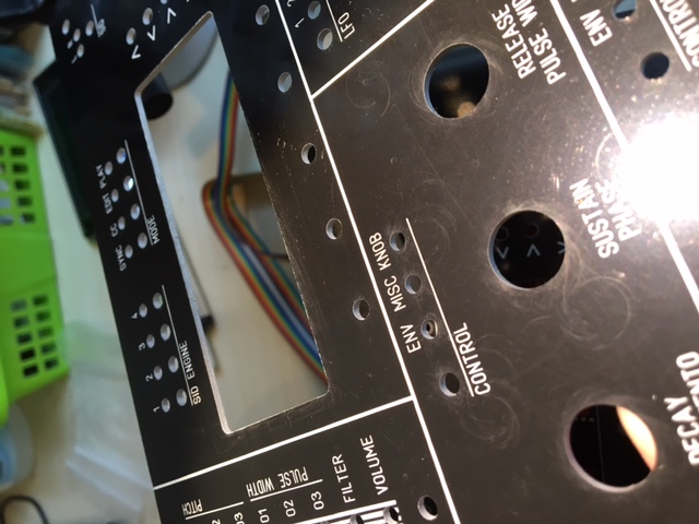
One of the only true scratches, also some scuffs. Again, looks quite a bit worse in the picture than it does in real life). This is one of the worst blemishes on any of the panels.
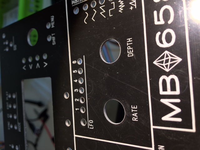
Tiny "L"-shaped extra bit of screenprint, no idea why it's there, but it's covered up by the PT-10 case.
A couple blemishes/imperfections in the solder mask of this one.
Probably the worst-scuffed rear panel (in general, the rear panels are a little worse off than the front panels). Especially see along the top (to the left) edge.
-
 1
1
-
-
Update 9/5, one set left.
Hey all. I had a small batch of cheap MB-6582 panels made, and as I only need one set, I thought I would pass the rest on to the community. Before selling them though, I want to make very clear what these panels are, what they aren't, and how they differ from the standard designs (very slightly).
What these panels are:
- They're pretty good looking.
- They're inexpensive.
- They're made to high precision. The fit on my personal MB-6582 is perfect.
- They're professionally made. The screen printing on them turned out pretty nice.
- Technically, they're aluminum PCBs. There are no circuits (there's not even a copper layer), just soldermask and screen print, but getting them made by a PCB company is why they're cheap.
What these panels are not:
- They're not perfect. I really want to stress this. They're not perfect. If you're kind of anal about scratches and blemishes, these are not the panels for you. These are the Monets of the panel world: from far away, they're ok, but up close, it's a big ol' mess. Some issues they have: various scuffs, a couple light scratches, some soldermask blemishes. There's a stray bit of screenprint on all the rear panels, but it is luckily covered up by the PT-10 bezel. Just check out the pictures, I tried to get a good shot of all the different issues.
- They're not Front Panel Express or @julianf-level of quality. The edges aren't perfectly clean (not messy though), and the screenprint, while nice-looking, isn't 100% perfect. There is definitely no etching or engraving like you'd see from FPE or Julian. If you're one of those anal folks I was just talking about, you're much better off spending the extra money with them to get something really nice.
- They're not durability-tested. I know other synthDIY folks have used this manufacturer for front panels before, and I have't heard anyone complain about issues (besides the already-mentioned cosmetic ones), but I can't guarantee that the screen print will hold up forever.
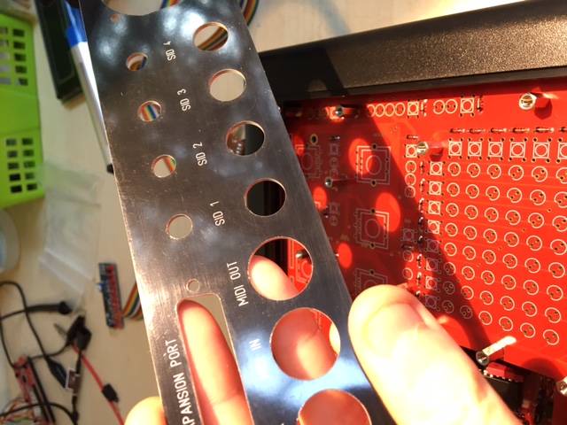
How these panels are different from the standard designs on the wiki (see photos):
- Added a small "MB?6582" graphic/text to front panel. Just felt weird not to have the name of the synthesizer on there somewhere.
- Added silly psychedelic graphic behind LED matrix.
- Added front panel corner mounting holes (not countersunk).
- Enlarged mix out jack cut-out on rear panel to accommodate 1/4" jack.
- Added "MIX OUT" label to rear panel.
All in all, I'm pretty pleased with how they turned out. I think my descriptions probably make them sound worse than they are, but I just want to be totally honest about how they look. Again, they aren't perfect, but they're much cheaper than any other option short of drilling your own at home. I will be assembling my MB-6582 using these panels with zero hesitation about how they look, and definitely no hesitation with their construction quality. If you have any questions or concerns, definitely contact me. (Edit: I also want to mention, a lot of the scuffs seem to be pretty shallow, and you might be able to buff/polish most of them out if you are careful and have the time. No guarantees, and I wouldn't try to buff too near the screen-printing, but I thought it worth mentioning.)
I'm thinking $38 shipped inside the US for a set (front and rear). I am happy to ship internationally for $35 plus actual shipping. I only did a small run of five sets, and this is just enough to cover costs. Because of the issues described, I'm treating these like "b-stock"; in other words, consider them "as-is" products with no returns. (Obviously if they show up bent from shipping or otherwise fouled-up in a way I haven't described or implied here, we can make arrangements for a refund, but I don't want to hear any complaints about scuffs and blemishes.)
Also, if anyone wants to order their own run of PCB panels (you could get them even cheaper if you have them fabbed from regular PCB material), I'm happy to privately share my Gerbers and/or DipTrace files. It's pretty easy to do yourself from the already available DXF files, though.
-
So I know the fan probably isn't strictly even necessary, but I just like it. So I'm curious for those of you who decided to install a fan, does it blow the hot air out of the MB6582 or does it suck cool air from outside?
-
On February 21, 2017 at 6:59 AM, sslneve said:
Hello can I still get the knobs? Help me thanks
There's a more recent group buy thread than this one, hopefully getting started sometime in the near future. Keep checking back there.
-
Yup, backwards, sorry. If the 5V were the backwards one you could readjust the wiring but I'm pretty sure you should just desolder the 9V.
-
1
-
-
Thonk carries some decent choices...
https://www.thonk.co.uk/shop/1900h/
https://www.thonk.co.uk/shop/sifam-soft-touch-encoder-knob/
https://www.thonk.co.uk/shop/intellijel-style-knobs/
https://www.thonk.co.uk/shop/make-noise-mutable-style-knobs/
My only real problem with these is that they're all kinda small. Nothing that makes me want to reach out and twist, like the ALBS knobs. Can't seem to find any knobs as deep as the ALBS either.
-
Sounds good. :)
-
On 10/24/2016 at 9:47 AM, latigid on said:
I might do a bulk order in the future, I'm in Germany and I'd consider a run of 1000 or so. But probably not until next year at the earliest.
If it's more convenient for someone to organise one now, then please go for it.
@latigid on Any movement on this? I'm still not in any rush, but I'm wrapping up my MB-6582 in the next month or two, so I'm just trying to figure out what my options are. Basically, if you're still thinking you might run a large GB here soon, I'll wait for that, but if it's totally up in the air or not happening for six months, I'll probably try to get my own GB going here very soon.
-
Don't forget to use their current discount code (check Facebook) or wait till the next discount code shows up.
-
I think Tayda has dual-gang log pots.
-
1
-
-
I'm looking to grab one myself, if anyone out there is listening ;)
-
Either way, I think the wiki is a better place for those scans, with the rest of the documentation, as opposed to buried in the forums somewhere.
-
4 hours ago, latigid on said:
Thanks for the writeup, and I second the idea of making a wiki entry. The diagram needs work, maybe choose a better-contrasting font. As well, the correct connections/mods/swaps can be indicated on a PCB diagram for improved clarity. I think someone may have done that already.
What I would really love is a high-res scan or clear photo of an unpopulated board. I didn't think to take one, and I couldn't find one on google images. I just know that when I was a beginner, PCB diagrams were kind of hard to follow.
-
That's a really good idea; I actually haven't figured out that part of my build yet. I had actually planned on connecting J1A to a panelmount barrel jack so I could use a standard wall-wart without modification. Upon investigation, however, the placement of J1A interferes with the obvious placement of the barrel jack on the rear panel. So I may end up putting a 7-pin DIN on a wall-wart, as you've done.
Either way, once I have a permanent solution, I'll take pictures and add it to the tutorial.
-
I proofread this a couple times, but if anyone spots any typos or corrections that need to be made, or has any suggestions for info to be added, just let me know and I will edit.
I hope this is helpful to someone! I know it's not much—just compiling known information into a step-by-step format—but I wanted to contribute back to the MIDIbox community in some way.
-
First off, here’s a link to the original thread on this topic, from which most of this tutorial is derived. Many thanks go to @Altitude, who first conceived of this solution and figured out the wiring details.
There’s nothing wrong with the old thread, and there’s a lot of good information there, but I thought it would be good to get a fresh thread going with a clearly laid out tutorial. The old thread, while useful, has a lot of obsolete and occasionally conflicting information, is organized as a discussion between members rather than a tutorial, and is missing some possibly important information depending on the parts you use. So while the old thread is great reference material, this is more of a step-by-step, newbie-friendly guide. If the mods disagree, feel free to merge this into the old thread.
Quick note: I’m considering an MB-6582 stuffed with only 8580/6582 SID chips to be the “default” configuration for the purposes of this document (especially the photos at the end), but I’ve tried my best to cover any configuration of SID chips wherever possible. I have not personally built anything with 6581 chips though, so anything regarding such setups should be considered theoretical at best. Double-check before you install. The two basic types of SID chips require different voltages (12V for 6581, 9v for 8580/6582), and if you mismatch the two, you could fry a precious SID!
What are we trying to do?
The MB-6582 is designed to be fed 9VAC and 5VDC, i.e. what a Commodore64 PSU puts out. This is convenient for a few reasons—the MB-6582 needs 2-3 different voltage rails to function anyway, and a lot of folks making SID synths are probably already interested in C64s and may have an extra PSU—but inconvenient for other reasons—AC power must be rectified immediately, C64 PSUs are notorious for breaking and taking out SID chips with them, and any replacement PSUs are expected to also put out multiple voltages, which is uncommon and expensive. This tutorial aims to solve for these disadvantages by reducing the power input to a single 12-15VDC source (aka a common wall-wart).
This is accomplished with a switching voltage regulator. Normally, if you tried to regulate 12V down to 5V with much of a load, your linear regulator (good ol 7805) will overheat and shut down. It’s just too much energy to dissipate. However, in the past, your hands were tied, as more efficient regulators (switching instead linear) tended to generate too much noise to be used in a synthesizer. Technology marches on though, and today’s sVregs are good enough that any noise is inaudible. So basically, you feed 12VDC into the MB-6582, regulate it down to 9V with a linear 7809 for one rail (a drop of 3V is much more reasonable than a drop of 7V) and use your 5V sVreg to generate your 5V rail. (Alternatively, you can feed the MB-6582 15V, use a 7812 and both 9V and 5V sVregs to get 12V, 9V, and 5V to run a mixed SID environment, but more on this later.)
A few people in the old thread were getting confused about the PSU Options in the official build documentation, and where this setup falls in those categories. It’s closest to PSU Option C, but for the sake of simplification, let’s just call it PSU Option E. It’s its own thing. There are a few “sub-options” depending on whether you want to run all 8580/6582s, all 6581s, or a combination, but as a whole, this option stands on its own.
Fwiw, like the official build docs, please read the entire tutorial before proceeding. Let’s get started.
How does the BOM change?
- You will need a power supply. For 6582/8580-only builds, you want 12VDC. For 6581-only or mixed-SID builds, you want 15VDC. For either setup, you probably want at least 1.5A. You may be able to get away with less amperage, especially if you’re not using the maximum number of PICs, SIDs or LEDs.
- You will not need B1 (the bridge rectifier).
- You will not need C14 or C13 (although if they’re installed already, it doesn’t hurt anything).
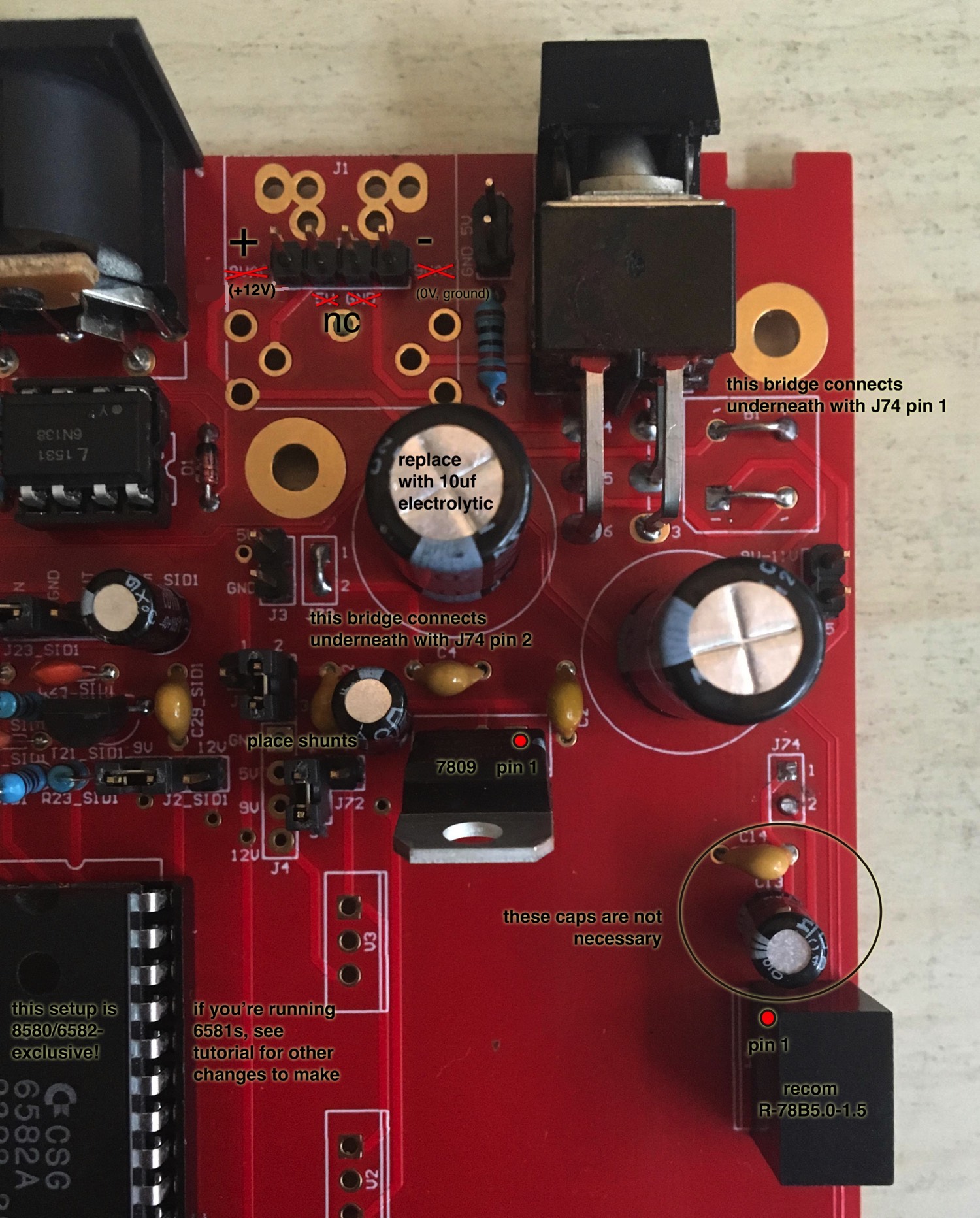
- C3 will be 10uF instead of 2200uF (you can just steal C13 if you’ve already ordered).
- V4 will be a 5V switching regulator. Recom R78B5.0-1.5 (Mouser part #: 919-R-78B5.0-1.5) seems to be a good choice. There are other parts that will probably work. There are other brands, other Recom parts, etc. Some of them are discussed in the older thread, although some of those options are now obsolete. Pay attention to current output. For a full 4-core, 8-SID, complete control surface MB-6582, 1.5A is recommended, although. You may be able to get away with 1A, especially if you’re leaving out some SIDs/PICs/LEDs. If you don’t want to experiment, just buy this one.
- You will need a few small jumpers (I used headers and shunts, but discarded resistor legs soldered to the board will work fine too) and a couple longer, insulated jumpers (I used some solid-core hook-up wire I had handy).
- If you’re installing 6581s (exclusively or as part of a mixed-SID setup), you need a 7812 voltage regulator. (More on this later.)
- If you’re installing a mixed-SID setup, both 6581s and 8580/6582s, V1 changes from a 7809 to a 9V switching regulator. Recom R-78C9.0-1.0 (Mouser part #: 919-R-78C9.0-1.0) seems to be a good choice. (More on this later.)
(Technical note—ignore this if you don’t care *how* things work and just want to get to building—on why we change the capacitors… If you check out the MB-6582 base PCB around V4, you’ll notice that it’s not actually connected to the rest of the circuit; it needs to be jumped in via J74. We are actually installing V4 backwards from what the original design expects, which allows us to get rid of a couple redundant caps and reduce the size of another. C14 and C13 are meant to smooth the output of V4, but now they’re on the input, which is already being smoothed by C1 and C2. C3 and C4 are meant to smooth the input of the 5V line (which would be separate if using a C64 power supply, but isn’t in this setup), but are now on the output of V4, so C4 takes over the function of C14, while C3 is reduced in value to take over the job of C13. You may notice in the older thread that nobody else has messed with these capacitors. This is fine in a lot of setups; they’re just smoothing what are probably already pretty smooth power rails. However, an issue can arise with certain switching voltage regulators, where an excess capacitance load on the regulator prevents it from starting up properly, which in turn prevents then entire MB-6582 from booting. In other words, if you’re starting from scratch, set it up as instructed; and if you’re modifying an already-built unit, you can try leaving the capacitors as-is to see if it works.)
Alright, now how to build it…
PSU OPTION E
- Jumper pin 2 and pin 3 of J71. This connects V1 common pin to ground.
- Jumper pin 2 and pin 3 of J72. This connects V1 output to 9V rail.
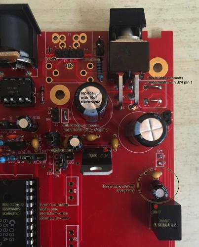
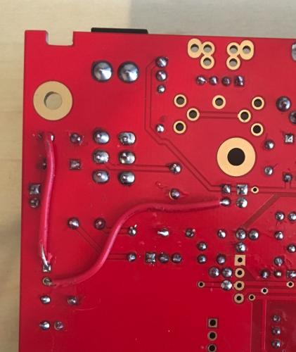
- Jumper pin 1 and pin 2 of J73 and pin 2 of J74. This connects the output of V4 to 5V rail (as well as a few smoothing caps). If you take a look at my photos, you can see I used just one piece of wire to jump all three pins—a short, uninsulated section on the top of the board to jump J73 pins 1&2 together, with a longer, insulated section underneath the board between J73 pin 2 and J74 pin 2. I felt that this was the cleanest possible installation, as it keeps all extra wiring on the solder side of the board. However, you may find it easier or prettier, especially if you’re modifying an already built MB-6582, to wire up slightly different points. Check out Altitude’s photos in the old thread for an alternate wiring scheme, or follow traces on the PCB (nice diagram here: http://www.midibox.org/dokuwiki/lib/exe/fetch.php?media=mb-6582:mb-6582_base_pcb_r2_color.pdf) to come up with your own.
- Jumper the “~” and “+” pins of B1 (the two pins closest to S1; see photos for clarification) and pin 1 of J74. Just like the previous step, you can use one piece of wire to jump all three points and keep the top of the board looking clean, or choose your own wiring scheme according to your needs.
- Jumper the “-“ and “~” pins of B1 (the two pins closest to C1; see photos for clarification). Important note: there are two pins on B1 labelled “~”. Pay attention to which one you’re bridging to where. Look at the photos!
- Install V1. Pay attention to pinout. The square (rightmost) pad is pin 1 (input).
- Install V4. Pay attention to pinout. The square (bottommost) pad is pin 3 (output). (If you’re curious why, go back and read that technical note you skipped earlier in the tutorial.)
If you want to use only 8580/6582 SID chips, you are done!
Make sure all your SIDs have a shunt installed at J1_SIDx and J2_SIDx connecting them to the 9V rail and you are good to go.
If you want to use 6581 chips only (NO 8580/6582!)
If you’re using all 6581 SIDs, with zero 8580/6582s installed, you can follow the above instructions with only two changes. Simply switch out the 7809 at V1 for a 7812 and connect a 15V DC wall wart instead of a 12V one. The advantages of this are that it keeps your rewiring minimal and keeps some smoothing caps that are absent from the 12V rail as labeled on the PCB. Of course, the disadvantage is that your 12V rail will be labeled on the PCB as 9V. If you never plan on opening your MB-6582 again, this is fine, but if you ever work on it again, or sell it to someone else who does, this could prove confusing. If you do this, set the shunts on J1_SIDx and J2_SIDx to 9V (which is really 12V).
You could alternatively install your 7812 in V2 and run a jumper between J72 pin 1 and V1 pin 1 (square pad). This adds an extra jumper (not a big deal, but ugly) and forgoes the smoothing caps on the output of your regulator (probably not necessary, not used in mixed-SID setups anyway), but would actually put your 12V on the rail labeled 12V. If you do this, set the shunts on J1_SIDx and J2_SIDx to 12V (which really is 12V).
Pick one and only one of these methods, and you are good to go.
If you want to use both types of SIDs
If you want to mix 6581s with 8580/6582s, things are just slightly little more complicated.
Start by following the 8580/6582 instructions above right up until you get to installing the voltage regulators.
- V4 stays the same—you still want your 5V switching regulator. Pay attention to pinout. The square (bottommost) pad is pin 3 (output).
- V1 changes from a 7809 to the 9V sVreg, as noted in the BOM changes. Pay attention to pinout. The square (rightmost) pad is pin 1 (input).
- V3 must be stuffed with a 7812. Pay attention to pinout. The square (topmost) pad is pin 1 (input).
- You must install an additional jumper wire between the input of V3 and the main 15V line. J72 pin 1 is an obvious place to connect to V3, and the J25 pin “9V-11V” (possibly unused pad) or pin 1 of V1 (shortest possible jumper) are good places to connect to the 15V line, though you have plenty of choices.
After that, place a shunt at J1_SIDx and J2_SIDx according to the type of SID you have installed there (12V for 6581, 9V for 8580/6582), and you are good to go.
No matter what type of SIDs you use, the only other thing to pay attention to is the polarity of your DC power. The two 9VAC pins of the power connector/header are your new 12 or 15VDC + and -. If you bridged B1 the same as shown in my photos (double check!), then the square (leftmost) pad of J1A, or the bottom left pad of J1, is +12V or +15V. The rightmost pin of J1A, or the bottom right pad of J1, is 0V (ground).
That’s all! Remember, before you install any ICs, test for correct voltages according to the official build documentation.
Here are some images. Sorry the text turned out so small, you will probably have to click on the image and display it full-size to read it.
-
1
-
-
Yeah, I think you're right about that. The 1.5A sVreg is already ordered and I never soldered the 1A one back, so I'll just install the new one when it shows up and keep the old one as a spare part. Seems like a handy little part for all kinds of circuits!
-
Looking over the MB-6582 PCB document and the original MIDIbox schematics, it seems a-ok. The sVreg is wired opposite how the PCB expects it. Because the 5V regulator is hooked into the rest of the circuit correctly via jumper wires, it doesn't really matter, and the only effect is that the input caps are on the output and vice versa. According to the MIDIbox Core schematic, the output of the 5V reg should have a couple smaller caps, while the big cap should go on the input (where there already is a big cap, C1).
I think I'll solder in a smaller cap, like 10uF, which is what the Core schematic indicates. If it works, I'll call it good, and if it doesn't work, I'll take it back out and call it good. (Edit: it works, calling it good.)
-
On 1/31/2017 at 0:09 PM, latigid on said:
Also:
If you have the large caps in there, removing them or adding the flyback/Schottky diode could help.
 @latigid on wins the day!
I was reading up on various DC/DC converters for an unrelated project this morning and stumbled on a datasheet that went into more detail about the "max capacitance load" and how it could stop the converter from starting up properly. I recalled your comment, did a little more research, popped C3 off the board and voila! Everything starts up just fine with eight SIDs stuffed. I already ordered that replacement sVreg, and may yet install it, since as Hawkeye points out, I'm already cutting it close without my CS installed, but for now the 1A seems to do the job.
Sooooo, C3. I think all it's doing is filtering noise on the 5V line. With the C64 PSU, it might have provided some protection from voltage spikes, but behind my sVreg, it seems less necessary. Running a quick audio test, it sounds totally silent to my ears. Is there any danger to leaving it out completely if no noise is audible? Analyzing circuits is not my wheelhouse at all, so it'd be good to hear some input on this.
(edit: And just to be safe, just went through each stereo output and confirmed that all four cores and all eight SIDs are firing as expected. I'll have to double check the SIDs more closely to make sure there are no blown filters, but the six that didn't come out of my known-working sammichSID don't appear to have ever left Wilba's original packaging, even though I got them elsewhere. Anyway, woohoo! I do believe this counts as a functioning MB-6582!)
-
Just added this to my Mouser cart.
It's a different prefix again, but it's the only Recom 5V 1.5A sVreg I could find (and other manufacturers had significantly worse ripple/noise ratings). I just want another set of eyes to verify that this is the correct part before hitting "submit."
-
Just now, Hawkeye said:
Thanks for measuring! 840ma of 1000ma is too close, as there isn`t even the CS installed... subtract 10% error and it will go into shutdown...
Upgrade the switcher to 1.5 amps... that is also the spec of the 5v rail of the original C64 PSU...
Many greets, Peter
Alright, makes sense. What's another $10? ;)
I went back through the Altitude thread and noticed that he's using a 1.5A sVreg in his build (not the Recom part, but an older, obsolete one). I only found one person using the 1A Recom in that thread, and it's not clear how many SIDs they were running or whether their MB SID ever completely worked.
What a power hog!
-
2 hours ago, latigid on said:
Also:
If you have the large caps in there, removing them or adding the flyback/Schottky diode could help.
@latigid on, just saw this, must have missed it while writing my own response. I saw this in the datasheet and thought it might be related, but didn't really understand what it meant.
Are you talking about the 2200uF caps? For the flyback diode, is 1N4148 ok? I don't think I have anything else handy. Edit: I do have a 1N4001 power diode here too.
-
Hah, duh. Wish I had checked this thread again before firing up the iron.
Anyway, pulled the R785.0-1.0 and breadboarded it for easier debugging. Double-checked that it's hooked up correctly by running it in this configuration: same results as before.
With my multimeter in series with the 5V line, I measure:
6 SIDs: 710-730mA
7 SIDs: 730-760mA
8 SIDs: 810-840mA
I also want to note that I get slightly different behavior when my meter is in series like this.
- No matter how many SIDs are stuffed (6, 7, or 8), the LCD acts kinda funny—like the contrast is worse or uneven, maybe the backlight is dimmer and it is not nearly as responsive.
- It seems to boot with a 7th SID installed, but still not that 8th one.
- A couple times, it seemed to struggle to boot with just six SIDs installed. It would hang on "Launching CS..." or reboot itself. Perhaps this one is down to iffy connections. Between the breadboard and the alligator clips/probes, it wouldn't surprise me if something just lost connection briefly, especially since this happened just a couple of times while testing and retesting and testing a third time to be sure, but figured I should mention it for the same of completion.
So anyway, still kinda stumped.

MB-6582 fan: blowing or sucking?
in MIDIbox SID
Posted
Hmm, something to think on. As you mention, the fan is probably not critical enough to worry about to begin with (especially as my MB-6582 is all 8580/6582), but I'll try to be aware of the thermal situation. If I notice the front panel getting warm, I'll flip the fan around and see if it does any good.
Heatsinks are probably a better idea than a fan altogether, I should try to find some that fit my SIDs.