

jaytee
-
Posts
352 -
Joined
-
Last visited
-
Days Won
15
Content Type
Profiles
Forums
Blogs
Gallery
Posts posted by jaytee
-
-
Thank you. I tried uploading as attachments first, but the site was giving me trouble, maybe because I was on mobile.
-
How did I miss that?!
Anyway, that's great. I'm pretty sure my design places the Jack right around the same place. I need to double check that it'll clear those capacitors, but otherwise I'm pretty pleased!
BTW, thanks so much for all the help @Hawkeye. Pretty sure I literally would not be able to do this project without it.
-
 1
1
-
-
On September 29, 2011 at 4:13 PM, orange_hand said:
Hi,
today I received my new MB6582 rear panel which was made by Schaeffer AG in Germany. I love the German quality work :-)

As you can see it is still in its protective cover. You will recognise that I have modified the panel with some features:
- I increased the hole for the mix out jack
- The following descriptions were added: Mix Out, On/Off, MOD1-4, Audio Out, Fan
- There is now a hole for a standard on/off switch for the fan, as well as an indicator LED for the fan
- I also added the device name, the serial number of the box as well as the name of the builder :-)
I connected the fan with the switch and the LED:

I connected a cable to the mix out jack:

Here you will see the completely assembled rear panel:


Here is the final rear panel (apart from the pot caps, which I haven't installed so far):


I hope you also like the minor improvements....
Cheers
orange
Oh no, all the pictures are gone! I'm trying to redesign the rear panel and a 1/4" mix out Jack is high on my list of priorities. I'm trying to get a sense of how to position it so that it'll fit with the CS installed and I can't get an idea of where it should be placed.
-
Have you seen this page re: LCD cable?
-
Here are photos of my single-supply wiring.
basically exactly the same setup as Altitude. I chose slightly different soldering points for the insulated jumpers (combining them with small component-side jumpers) just to keep them out of sight, but they're functionally identical. This is a 9V only solution, with a 7809 installed alongside the Recom 5V regulator from earlier in this thread. Pay attention to jumper locations.
To hook up to a power supply, looking at the first photo (component side) connect + to the left-hand 9VAC pad and - to the right-hand 9VAC pad.
-
I don't suppose anyone can suggest a power supply? My head is spinning trying to find one that isn't a cheap piece of junk.
OTOH, would a switching supply maybe be ok in this case, since all voltages are getting run through regulators and filtering caps?
-
I measured voltage on the 5V line with six SIDs installed vs seven SIDs, as @Hawkeye suggested. 4.99V and 2.45V, respectively.
-
Alright, I did some testing.
First off, I gave the solder side of my board a thorough once over. Cleaned up questionable joints, got rid of flux splatter and errant blobs of solder, just generally cleaned it all up.
I powered it up with four SIDs again—numbers 1,2,7&8—just to be sure that still worked. All good. I measure current draw, it's around 350mA.
I stuff one additional SID in slot 3. It works. Try it in slots 4,5&6. It works. Leave it in slot 6.
I stuff a sixth SID in slot 3. Everything still works.
I stuff a seventh SID in slot 4. Nothing. Try it in slot 5. Nothing. Remove that SID and try the eighth SID in slots 4 and 5. Nothing.
I remove the working SID from slot 3 and stuff the eighth SID there instead (so again, back down to six SIDs). It works.
So it seems that it's only related to how many SIDs are stuffed, not where they get stuffed or which SIDs I use.
Now I'm thinking it really is a matter of current draw. I test the current draw with six SIDs installed (working). About 550mA. I install a seventh SID. Current draw drops to about 360mA and as expected, the MB-6582 doesn't boot.
Is my power supply crapping out? This is the one I use. I've been using it with my sammichSID for years.
Any ideas?
-
I will measure current draw later today; I ran out of workbench time yesterday.
What other problems might cause this issue?
-
So I just finished my MB-6582 base PCB. I tried it out with the first two SID chips mounted, success! Beautiful. I mount the other six SIDs....nothing. No startup tones, no LCD activity (not even a backlight). Uh oh. I removed half the SIDs (cores 2 and 3 FWIW) and everything seems to work again.
Am I correct in thinking this is an issue of current draw? I am using a regulated 12V 1A supply (using Altitude's single supply approach), which I figured for sure would be enough juice (in the thread for the single supply, Altitude mentions only drawing 800mA with eight 6582s and a fan, and I don't even have a fan). Perhaps not? Is there anything else it might be?
edit: And if it is just a matter of amperage (looking through old threads, I do see a few people referencing their MB-6582 drawing 1A or slightly more) can anyone suggest a decent power supply? I hate looking for this stuff; I don't want to run my precious gear off the cheapy-cheap switching supplies that are everywhere.
-
Thanks! I had a vague suspicion it was just the LCD—the datasheet doesn't mention brightness control at least—but couldn't find any other references to that being a possibility, so I immediately jumped to user error.
I tried your LED test real quick and...hmmmm. It actually causes the brightness of the screen to work...somewhat (limited range). In any case, I won't mess with it until I have my final display hooked up; this one is just for testing.
-
So any ideas about my backlight brightness/luminance?
I checked that the trimmer was working, and it is; voltage varies between 0-5V as it is turned. But by the time those lines make it to my LCD, it's a constant 5V no matter what. I'm not totally clear on what the little circuit near the trimmer does, with the transistor and resistors, but it seems to be the problem. Is it possible I burned out my BC337 while soldering it in?
-
Success! (Though my brightness knob still doesn't seem to do anything...)
-
Ok, took it out of the breadboard, soldered everything up, double checked my connections, fired it up....nothing. U solder some wires to try out 4-bit mode, nothing. But at least now it's a consistent nothing rather than constantly changing gibberish, which indicates to me that the breadboard *was* an issue, just not the only issue.
So the "nothing" I'm getting is two full lines of completely blacked out characters. Contrast knob does nothing. Backlight turns on fine, but as before, brightness knob does nothing. Checked the input voltages and they come out to 5V as expected. Not sure where else to start checking.
any ideas?
edit: just found the LCD connection test app. trying it now...
double edit: I ran the app, everything checked out, felt *really* stumped, then realized I've have it connected backwards the entire time somehow, even though I double and triple checked before hooking it up every single time. WTF.
-
Already have your CS thread bookmarked! ;) It's one of the best pieces of documentation for the MB-6582 around (and I almost never found it because it's hidden in some other forum!). I'm 90% sure I got the cable mapping right (using both your guide and my datasheet), but I'll double check as I solder it.
-
3 hours ago, latigid on said:
As for LCDs: don't be such a cheapass! The price and availability of these has come down hugely over the years. I would even go a step further and look at installing an OLED, just make sure it can handle +5V logic. Also ensure the mechanical fit works with the mounting holes/cutout on the CS PCB. Usually these things are pretty standard, but you can never be too sure.
I actually looked into OLEDs, but was mostly put off by the fact that the MB-6582 is built specifically for LCDs in terms of depth. Seems like an OLED will be really sunken in or require a bit of jiggery to mount it on top of the CS PCB. I am curious if that Crystalfontz I linked to will look as nice in person as it does in the picture. It's got beautiful contrast and almost looks like an OLED. I am skeptical, but otoh, their other photos of their LCDs look pretty much how I'd expect LCDs to look...
Regarding soldering jumpers for 8-bit mode. I saw and read through that thread, but I am still left not really understanding the *why* of it all. It seems like some folks leave the MB-6582 in 4-bit mode but build the LCD cables according to 8-bit mode instructions and things turn out fine.
11 hours ago, Smithy said:IIRC if you flash the MIDIBOX sid firmware file it is set to work with a 2 line character display.
And if you flash the mb-6582 firmware it is set to work with a 4 line character display.
This is way of getting around having to edit code.
That still leaves me wondering if anything needs to be adjusted for using a 16x2 instead of the standard 20x2? Will the 16x2 automatically truncate those last 8 characters, or do I need to change the firmware to adjust for the smaller test display? I haven't even uploaded the MB SID app yet, just vanilla MIOS.
-
Good to know. Maybe the blurb in the wiki about using DXFs at your own risk should be revised? It definitely had me under the impression that I was gonna foul everything up by using an exported DXF.
Still gotta figure out how to place the corner screw holes...
-
Isn't DXF just a vector file? Does it maintain accurate measurements in the conversion somehow? The MB-6582 warns against this. Sorry, I'm really new to anything nearing graphic design.
-
What's the best way to get accurate measurements for a front panel? Measure the PCB with calipers? Or can this information be extracted or gleaned somehow from the available FPD files? I am very keen on making my own panels but FPE is way too pricy.
The other problem is that I don't really want to deal with the rigmarole involved in eliminating external screws (though props to Wilba for figuring that out), but the file that includes screw locations is a dead link now.
-
What's the best way to get accurate measurements for a front panel? Measure the PCB with calipers? Or can this information be extracted or gleaned somehow from the available FPD files? I am very keen on making my own panels but FPE is way too pricy.
-
I've read all the relevant documentation that I could find on LCD character displays—mostly this, this, this, and this, along with various sections of the MB SID documentation and dozens of forum posts—and I'm still left with a few questions...
First off, where I am in my project. Questions are down below. I have my MB-6582 power section fully built. I went ahead and built all four cores (I was going to do one at a time, but after you solder in all the resistors, capacitors under sockets, sockets themselves, and headers, there's only like three more components per core to add). I checked all my voltages and everything checks out. I inserted my first PIC and successfully uploaded MIOS (though not the SID application yet). So everything seems good so far.
I haven't ordered my 20x4 LCD yet (more on that later), but I have a 16x2 LCD handy (this one) and figured I would use that to test while I wait on more parts. The MB SID manual says that 16x2 is supported, just not recommended because of its size. I read the above documentation, get a cable all ready, connect it to the LCD, and...nothing. Fiddling with the contrast trimmer and the cabling, I manage to get a few weird things to display, but nothing that indicates things are hooked up properly.
Now, I strongly suspect that it's either a mechanical issue with my connection (its hooked up somewhat haphazardly through a breadboard, rather than soldered) or a mix up with pin connections. But! before I go chasing phantom soldering issues, I am hoping to clear up a few questions I have, just to rule stuff out and gain a better understanding of how everything works.
HERE ARE MY QUESTIONS
First, does anything need to be changed in the code to support a given size of LCD? Like right now, I just have basic MIOS installed on my PIC, v1.9 as available as the top download link on this page; should I expect it to display startup information on any size (2x16 or 20x4, for instance) of standard LCD, or do I need to tell it what size to expect somehow? How about once I install the MB SID app?
Second, 4-bit mode and 8-bit mode. My understanding is that the MB SID app wants to run LCDs in 4-bit mode. Some documentation indicates that a special cable wiring setup is required for this (seen here), but while trawling the forums for information, a lot of folks suggest not to worry about special wiring. Not really sure what's what here.
Third, can anyone offer a wee bit of guidance wrt choosing an LCD? I was looking at Crystalfontz and this LCD looks particularly striking. Green on black! Looking at the specs, I'm 99.9% confident that this part is compatible with the MB-6582. Only thing holding me back is the price: $25 once you add shipping. Meanwhile, there are 20x4 LCDs from China on eBay for like $6. I understand that you get what you pay for, but I'm wondering if anyone can comment on where that extra $20 goes on a Crystalfontz. Nicer colors? Less likely to break? Better contrast? More responsive? All of the above?
Last, my backlight trimmer doesn't seem to affect anything. Backlight is on and at constant brightness no matter how this trimmer is set. I think I'm missing something obvious here.
Now, like I said, I understand that the simplest explanation is that I just don't have things hooked up securely or properly. I just figured this would be a good chance to stop and ask some questions that were bothering me (and probably only still bother me because things didn't work on the first try).
-
I feel like I've had this issue before as well. IIRC, I always just worked around it by assigning LFO depth to a spare envelope. I always assumed it was down to user error. :o
-
-
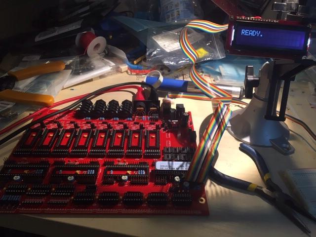
Just wired this up this afternoon. Seems to work like a charm!
MB-6582 current draw
in MIDIbox SID
Posted
Ok. So I had a cheap wall-wart Amazon Prime'd to my house. Didn't want to spend a lot of money on the off-chance this wasn't my problem....and I'm glad I didn't. Hooked up to a 12V 2A supply, I have the same issue. Up to six SIDS, everything is gravy; once I put a seventh and/or eighth in (no matter which SIDs or which slot) then MIOS fails to boot, LCD backlight doesn't turn on and basically nothing happens.
Is my 5V regulator the next thing to check? Is there any way to check it without just ordering a new one?