MrAureliusR
-
Posts
6 -
Joined
-
Last visited
MrAureliusR's Achievements
MIDIbox Newbie (1/4)
0
Reputation
-
 This seems to be the exact problem I'm having, I really can't figure it out though. I got my core and SID modules in the mail, stayed up late assembling them (and did a very nice job, I'm really proud of myself). I spent most of the next day troubleshooting but my original problem turned out to be my programmer wasn't programming the PIC18F4685's config bits properly, so after fixing that -- voila! MIOS Studio detected it, I was able to upload MIOS and then the SID application, and it worked! I used both my MIDI interface (the same one I used to program it over MIDI) and my keyboard to play music, which I had outputting through a small speaker just for testing purposes. Great, I thought, it sounds awesome! I played around a bit, using SysEx to send new patches into the buffer (I'm going to install my BankSticks today) and everything was perfect. I went to sleep, then today I sat back down to play around with it, and for the first few minutes it was sort of working... but then I noticed the MIDI IN light was flashing, as if it was in bootloader mode. So I opened up MIOS Studio, and yup -- it detected it, saying bootloader is up and running. So I scratched my head, shrugged my shoulders and tried to re-upload MIOS. It started to send it, but after a second or two it stopped with "Upload aborted due to error #11: MIDI IN Overrun Error". I fiddled around, trying to get it to work again, but no such luck. I do have two other 18F4685's so I tried blanking another one, burning just the bootloader (and getting the config bits right the first time!) and inserting it. This time it was definitely working in bootloader mode -- every second or so it sends it's ID or whatever byte it is to MIOS Studio, which immediately recognizes it... but I get the same error when I try to program it! At first I noticed that when it was sending data to program MIOS there was also a bunch of data coming through in the MIDI IN window -- basically the same byte it sends when it's waiting for code to be sent to it, only much faster. Basically (it seems) every byte sent to it would trigger it sending that same byte back. However, I wasn't paying close enough attention when I first programmed it, so I'm not sure if this is normal or not. Two-way communication during programming seems to make sense, so this may be irrelevant, or it may be a symptom and not the problem itself. I also spent quite a bit of time checking all my solder joints to make sure nothing was shorting out. But there can't be -- everything was working fine yesterday! That's what is really frustrating -- everything was working perfectly and I literally changed nothing -- just sat down and attempted to pick up where I left off last time... Really not sure what I should do. Does anyone have more information about that error? Is it referring to the PC end or the Core end? Any and all help is appreciated. I've been trying to read all the info about troubleshooting the Core than I can, but I can't seem to find much on this problem.
 -
sammichSID, intermittent shorts to ground around voltage regulators?
MrAureliusR replied to jaytee's topic in MIDIbox SID
Can you post some numbers of what you're seeing? -
sammichSID, intermittent shorts to ground around voltage regulators?
MrAureliusR replied to jaytee's topic in MIDIbox SID
Instead of measuring continuity, measure resistance. The threshold of multimeters for what is 'connected' can differ. It might be right on the edge of your meter's threshold so you get an intermittent beep, but its probably actually fine. Especially if you're confident in your soldering. Measure the resistance and post the values here. Plus what are these particular pins for? Obv the one on the regulator is ground but what's the other one? If its a voltage rail that has a capacitor going to ground nearby sometimes the ESR is low enough to trigger continuity (happened to me once a while back) and makes you think there's a problem when there isn't. (Or sometimes there is a problem like a bad cap or a short to ground) -
I hear everyone referring to DINx4 - that's just the regular DIN module right? And when you say I need 1 1/2 DINx4 you mean 1 and a half of the 4 inputs or 1 and a half full modules? Just curious as I only ordered 1 DIN kit.
-
Hey there everyone! I'm brand new to this forum (and MIDI for that matter) but fairly experienced in electronics. I'm going to order the Core and SID modules in the next few weeks. I have a C64 that I was going to harvest the SID from but I also have another on the way from an eBay seller. I have read basically all the info on the uCApps site regarding the SID V2 but I still have a few questions. Is it true that all I need to get started is the Core and SID modules? I have plenty of PIC 18F4685s so I'm planning on ordering the kit without one. I've got a few different ways to burn PICs. I just want to make sure I'm using the correct .hex file - can someone possibly link me to the latest stable version? I also run Linux so if needed I can compile it myself. I am going to also order an LCD plus encoders after I build the basics, so I can have an interface. Is all I need for this the DIN module? Is it important to get the PCB or is it easy enough to build on some proto/stripboard? Obviously I'm going to need a MIDI keyboard controller for the unit once it's built. (Can anyone recommend a cheap small basic MIDI controller keyboard? I just need something simple for testing. I've heard I can just interface to my computer as well to send MIDI commands?) For some reason it wasn't clear to me - is the audio out on the Core board or the SID board? If I were to build an FM unit in the future can I simply use one core module? I apologize if these seem overly noobish. I'm very enthusiastic and I tend to dive into projects head first so sometimes little things escape me. I'm looking forward to interacting with the community here! Thanks! EDIT: I already answered a few of my own questions. The audio in/out is on the SID board. And it looks like all I do need is the SID and Core to start making noise :smile: Also, am I right in thinking that this LCD:http://www.farnell.com/datasheets/1697099.pdf will be able to interface directly with J15? From what I can tell the pinout is perfect, and it's in DIL format which makes it even easier to interface! Never mind, screwed that one up royally.
-
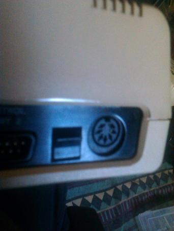
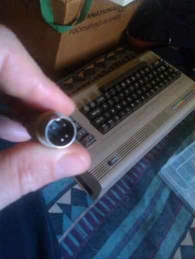
I just wanted to point out something you mentioned earlier in the thread. You said all the eBay power supplies are 4-pins -- ALL C64 power supplies are 4pin, they just use a 7-pin connector. At least in North America this is true. The top 2 pins are +9VAC, the bottom is ground, and the one to the left or right of it is +5VDC. See pics attached of mine!