Phatline
-
Posts
1,285 -
Joined
-
Last visited
-
Days Won
72
Content Type
Profiles
Forums
Blogs
Gallery
Everything posted by Phatline
-
with 32F4 you have to solder as well, there exist also (like on the LPC Board) a "Motherboard" > the CORE. the LPCore has 4 Midiconnections 2in/2out, on board, while 32F4 has none > where you have to built external Midi-IO-Boards....since for easier cable connections between the boxes you have to built external Midi-IO-Boards in any (your) way (LPC or 32F4) For me, i dont buy LPC Cores anymore... because i need the additional Performance of the 32F4 for my programms.... anyway in the past it was a compact solution, witht that Midi-IO-s onboard.
-
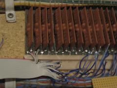
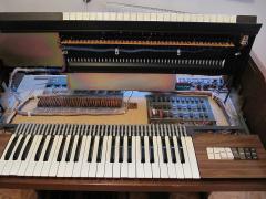
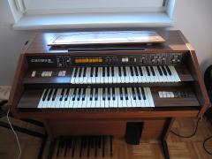
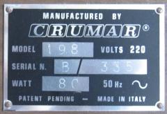
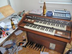
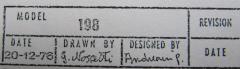
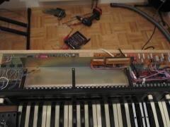
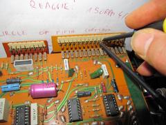
CRUMAR 198 (1976) i love that device... i did not learned keyboarding... but with that thing i start it by by doing... i was always a step-setter...so excuse that i dont find "the right notes" > newbee well i have great planes with it. built in my triggermatrix, which is some kind of play help, rythm automatic and so on... better you watch my video to understand.... @ the moment only the upper manual is midified with a Core32, and my program "triggermatrix" on it... the basic idea is: Connect a drummer, or rythm machine via midi to it, the drum trigger -"re-Trigger" the Key-notes which i press, i can deside via a Matrix which drumtrigger triggers which manual... also there are "song parts" to switch between Trigger-Presets, and Roll-Prests...also the gate length can be changed, and random trigger killer is also integrated... and much more... how ever , i want leds duo-colour-leds over each Key to show me the last Keys i have pressed... because, when i press a chord-set, which get repeated via the drum trigger...no it sounds... and sounds... meanwhile i go to the lower manual and play, or do bass pedals, or do reverb or drumsequencing or drumsounding... after a few seconds i have vorgotten which dam chords i pressed on the upper manual... so this is a must, i know how to do that... soldering a few weeks of course... also the leds will show me fittings notes in the circle fifth... and of course the pressed keys are indicated on the lower manual to over all octaves, in order to learn how to play, while i play... a circle of fifth note corection, which shifts the ohter manual when playing the other, and then falling back again...and also automaticly bass folwing is plan... but up to now i am very happy with this upper manual and the midicontroll via bcr2000. i think i will make the UI via designed PCB which i will order then, because i need 2time the same UI i think it is very clever to make that right...... i also want to replace those Registers via Potentiometers aka "Zugriegel"... also i want to add a triggered Lopassfilter for each manual... and much more of course... but enough, now Videos for ears and eyes, and pictures for your eyes and brain - have fun! well i have. Swell pedal via foto resistor and a 24V light pulb! old psu amp and Loudspeaker, i romed amp and Louspeaker and replaced the power supply the new one a "bit oversized"... but that parts i have lying around for 15years!!! (never realized amp project...) spring reverb tank and foot pedals spring reverb magnetic driver removed rythm "engine" "walz tango march, slow rong swing rock genuine, bossa nova, bass-auto and chords will be replaced with a midibox core32 my program "triggermatrix" and real Drummachine!!! in order for that you can cut the whole cable-tree... but then you have to solder the orange and one of the dark green cables 2gether, in order to get the lowest octave from the lower manual to work..... there are 2 dark green cables, you have to take the one that goes to the lower manual to the manual - key spirals.. dout modules 5V and level shifter 15V (BC549)...there are 88 outputs for 44 keys, because, 44 are organ, and 44 are "piano" envelope types...while the piano swell down with the 100uF caps, the organs will be hold... the selfe eteched din modules. din wired, core mounted the shematic to midified that thing: THE 220 Ohm must be replaced via an 10-22K, and the 1K is also not right... i then used a 2K2... but that Transistor get warm and all 44 of them take a current from 0,5A!!!... the powersuplly was not strong enough for that (with the CORE and the LCD in addation...)... but i think that was of cours of dry electroly caps... burned finger caps? no more! video with jamsession is on upload...
-
 spring reverb "tank", with shock absorbing foods, mounting on the "ground" of the heavy organ, to keep it isolted from manual key presses and so on...
 -
 spring reverb electromagnetic
 -
 yessss I love it - a analog reverb > a spring reverb... i never had seen something like this... first see- first love... what genuis made shuch things - a ambassador of the the electro analog century... cool of course that the crumar 198 has a driver and a post amp for it...with the bought shematics i am able to boost the post amp... my plan is to feed the driver circuit with a dout-pin which will act as accent... with my trigger matrix i am then able to route drumtrigger impulses to boost the volumes rythmicly... independet from the organ sound rythmic sound structure which comes in...
 -
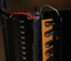
 The orginal power supply... it breaks down by an load over 1,5A...but maybe only because of them dry electrolyt caps... remarkable, in the left button corner - there is the shematic of the swell Pedal (aka volume) directly bevore the main-out plug, there is photo-resistor which driven by an 24V Light bulk, the light shines thru a whole or better a stripe which get bigger when you press the pedal...> real analog!
 -
 old psu, and loudspeaker amp... i removed the amp and speaker, and replaced the powersupply by an RING-CORE-Transformator one
 -
 replace the bower supply... or better adapt it... the parts where from an amp project that i never startetd anyway (15 years ago...)
 -
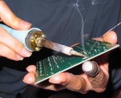
 after 2 weeks soldering, finally the first jam sessions with 2 bears and a bit N2O ;)
 -
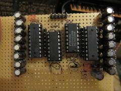
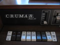
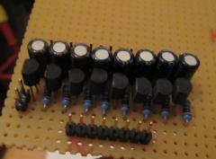
 the godfathers...
 -
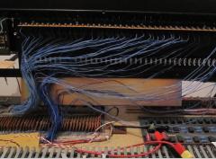
 no internal sound machine anymore
 -
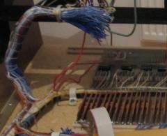
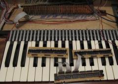
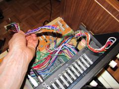 cut all wires...and connect dark green and orange to get the lower manual working
 -
 bridge the rythm machine to get the lower manual working
 -
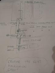
 if you want to remove the rythm engine and all it cables... you can cut all cables going to the rythm machine accept....: the dark green and the orange one > you have to connect them togehter in order to get the left most octave of the lower Manual to work...elswere the keys make no sound...
 -
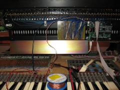
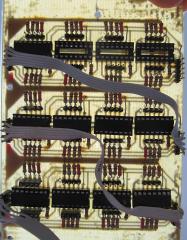
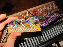
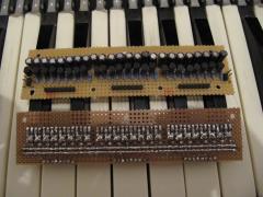 vectorboard design
 -
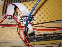
 44 keys...88 outpus... read 4 wireing
 -

e-organ, Key-switches to Ground > but Dout Gives +5V how to reverse?
Phatline replied to Phatline's topic in MIDIfication
yes it shares the same ground anyway i realized via BC549 Transistors. DOUT-PIN>10K>Base +15V>1K>Collector Ground>Emitter the whole thing x44 = 500mA... seems the 1K is a bit low ;).... 500mA is not much but.... enough to screw my Powersupply with dry elkos..... -
with midi you dont have to have chains... of course you can make chains....>>>> just build more midi IOs on your MAIN-Box >>> http://ucapps.de/mbhp_midi_io.html....
-
i also would do it via Midi --- or better OSC or Networkcables, to reduce midi cables... but osc on midibox you have to understand first...
-
256 individual inputs, of course but, you can use matrixes and scan that via software, and so you get more that 256 individual inputs.... softwareside i dont have done this... but others have done it... (search for BLM) 256 individual outputs, also can be arranged to matrixes... (also BLM, or SID LED-Matrix, Triggermatrix...), the size of it depends on the Shiftregister (HC595) and its maximal current, but there also alternatives with more current, or transistor circuits to drive bigger matrixes... networkcable - yes - make sure it has pair shields make sure that shields are connected to ground on one side of the cable The DIN and DOUT Modules (digital in, digital out) has to be connected via Connector Socket J1 to the J8/J9 Sockt on the Core Module J1 has 5 Contacts: Put following cables in a pair: VS, VD SI SC, RC To get more Amperes over the cable make it like this: VS VD SI SC,RC I dont know is it clever to put SC and RC in a own shield (pair?): VS, VD SI SC RC tips... well read that: Midibox NG for programming: I did not have to do with the Midibox NG... i took a MIOS32 skeleton and programmed my own concept. and it took a while to understand different things, and many things i dont understand up to now (like OSC and Ethernet) best you use Midibox NG... they have thougt about how a Midicontroller should work. when you want to use your concept of only core, and want to add more modules after time or on a running system, you have to add an "OFFSET to your shiftregister pin-outs) ....for example: activate a LED on a new connected module: LEDs are connected to Shiftregisters mainly "HC595" this registers have 8 PINs, you want to activate LED0 now, LED0 is connected to Shiftregister pin 0, All Shiftregisters are in an chain >>> all registers are connected serial one after a nother...if you connect your EXTRA/Modular Midibox to your CORE/MAIN-Midibox - then the chain starts on the core modules, and goes thru all DOUT-Registers in the MAIN-Midibox, until it goes to a connector where you plug your EXTRA-Midibox... well lets say there are 4 Shiftregister in the Main Midibox, the EXTRA-Midibox now starts with the 5th Shiftregisters... a LED gets software side activated in a way like this (pin, pin_value), so the first pin of your EXTRA-Midibox is: 32 (the pins start by 0, and 4 Registers * 8 Pins = 32 32+0 =32) so the point is, you have to program a offset to this >>> pin+Offset=real pin >>> the offset could be set by a "Connector switch", a Switch which is Connected to a DIN-PIN, if this DIN-Pin is acticated the Software set a PIN-Offset .... like an DEVICE ID that are my thougts... a LED on a specific pin (maybe pin 0) on a shiftregister (a shiftregister has 8 pin
-
e-organ, Key-switches to Ground > but Dout Gives +5V how to reverse?
Phatline replied to Phatline's topic in MIDIfication
checked the datasheet... i tryed 1K Resistors to 15V on the output but with that i got in "low Mode" 1,5V.... high 15V.... but i need 0V @low? a little bit info pleas- thankz -
no i would go for twisted pair - shieldet in pairs, or better individually. daisy chain... yes possible and necessery! all the used shiftregisters has to be connected one after a nother --- and if change the connecting you have to change your Coder!!!! (pin) it depends on your code - (memory on ic) and on the hardware: 256 buttons or 128encoders.... the same for DOUts but 16Led rings needs 24 dout pins http://www.ucapps.de/mbhp/mbhp_dout_8x16leds.pdf i dont made ledrings up to now...so someone other can help!
-
With one Brain hmm i see: 1. connect the boxes via 5pole shieldet cables (used for Shiftregister and Current) > CAT-Cable, and really keep them short! or 2. Use LINE-Driver - Boards to expand the cable length http://ucapps.de/mbhp_line_driver.html
-
e-organ, Key-switches to Ground > but Dout Gives +5V how to reverse?
Phatline replied to Phatline's topic in MIDIfication
a uln2803 for S-Trig... yes that makes the job any idea for a transistor array for a V-Trig 15V? for my other organ? @the moment i use BC337...by the way the Caps make the Piano-Trggers, while the standart output of the BC337 make the Hold-Organ-Trigger -
Midificate the ORGAN CRUMAR 198 add my Software "Triggermatrix" > to have some Playhelp with beats...
-