

Phatline
-
Posts
1,285 -
Joined
-
Last visited
-
Days Won
72
Content Type
Profiles
Forums
Blogs
Gallery
Everything posted by Phatline
-
1. ...you mean if a kick comes, the melody sequencer step one step forward? or 2. ...you mean if a kick comes, then currently playing melody sequencer note is played (and only then)... in second case i have programmed a MiosBased application called TRIGGER MATRIX take a look: https://vimeo.com/117018283 and: ...in the moment i try to activate the ethernet connection...and from this it will be easy to get acces from a tablet to the matrix...so tablet + lpc17 board + OSC software=all (in near future, its a matter of understand w.t.hell this client server ethernet works...) ...will take 3 more weaks or so to release TM.V01
-
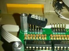 nimm eine Kunststoff Distanzhülse und schleife ziemlich viel weg.... wennst ka zeit hast nimm an schleifbock take a Distance-bolt and file one side away until it fits... take a floor stand grinder if you want it faster
 -
great link thankz! ... sometimes i got ideas to build such a optical or magnetic from scratch... the problem for me is the motor
-

OSC-Capacitive Multitouch + Raspberry Pi (no tablet Topic)
Phatline replied to Phatline's topic in Miscellaneous
TouchOSC need Apple or Android.... i could use some of thes Android mini pcs...but most of them have WIFI... I tried to install Android on Raspberry PI B > it is not booting - tried differnt sdcarsd and disk formats (fat, fat32) - dont work https://www.squirrelhosting.co.uk/hosting-blog/hosting-blog-info.php?id=22https://www.squirrelhosting.co.uk/hosting-blog/hosting-blog-info.php?id=22 next is to try linux on rasberry PI B in combination with nexusOSC http://www.nexusosc.com/drop/braid/ a freeware touchscreen Solution something like TouchOSC... but with my ubuntu laptop and firefox i dont run, now trying with rasperry pi and a Acer Multitouch Monitor. http://elinux.org/ArchLinux_Install_Guide -
i mean that: something like that with "digital pot": http://uk.farnell.com/analog-devices/ad5262bruz200/ic-digital-pot-8bit-200k-dual/dp/1438437 in kombination with virtual Knob/Pot/Ledring or LCD with Encoder > but ok you could also use those expensive motor-pots with a midibox MF-Module: http://ucapps.de/mbhp_mf_ng.html
-
for switching things: "audio read relais" driven by a MB doutmodule: http://ucapps.de/mbhp_dout.html ... or directly with the CORE Module http://ucapps.de/mbhp_core_lpc17.html > Connector 10 digital pots > ask others... i also like to know that - but for that you need (software)drivers (not standard here...) - also it is difficult to get the exact Residance what you need, the common suppliers have no digital pots, and if they have the have only a few resistance values (10K 100k and so on) maybe you must buy them direct from the semicounter manufactor (microchip, max, texxas instruments)... maybe you get free samples...maybe you must be a lot of them? maybe you start a bulkorder here?...
-
OSC - how to integrate in own application
Phatline replied to Phatline's topic in MIOS programming (C)
OK we testet out that this command OSC_SERVER_RemoteIP_Set(0, 10000000) results to 0.152.150.128 we bitshift 24 16 8 0, with that online calculator http://www.miniwebtool.com/bitwise-calculator/bit-shift/?data_type=10&number=0010010010010++&place=24&operator=Shift+Right (hopefully i handle that thing right) or this one http://www.convertalot.com/bitwise_operators.html 10000000dec >> 24 = 0 right 10000000dec >> 16 = 152 right 10000000dec >> 8 = 39062 false (should be 150) 10000000dec >> 0 = 10000000 false!!!! (should be 128) but: 128 in binary is 10000000 so: decimal >> 24 decimal >> 16 decimal ?????? decimal = decimal but how to combine that?.... i must assume that I CANT CHANGE THE IP the way i like . POINT. dont waste my live time for that anymore... - no osc. point. -
OSC - how to integrate in own application
Phatline replied to Phatline's topic in MIOS programming (C)
i thought maybe the IP-Set and NetMask set needs a pointer, so i tried this: #include <mios32.h> #include "app.h" #include "uip.h" #include <uip_task.h> #include <osc_client.h> #include "terminal.h" //set Device IP u32 deviceIP[4] = {1, 2, 3 ,4}; u32 *deviceIPpointer; //set UIP_TASK_Netmask u32 Netmask[4] = {255,255,255,0}; u32 *NetmaskPointer; void APP_Init(void) { // init terminal TERMINAL_Init(0); UIP_TASK_Init(0); //Set Pointer //Connection Setup UIP_TASK_DHCP_EnableSet(0); UIP_TASK_IP_AddressSet(1.1); //Host IP-Adress //uip_ipaddr1(1.0.0.0); //pointer? //uip_ipaddr2(2); //pointer? //uip_ipaddr2(3); //pointer? //uip_ipaddr2(4); //pointer NetmaskPointer = Netmask; UIP_TASK_NetmaskSet(NetmaskPointer); deviceIPpointer = deviceIP; OSC_SERVER_RemoteIP_Set(1, deviceIPpointer); //connections, IP OSC_SERVER_RemotePortSet(1, 5001); //connection 0-3, port OSC_SERVER_LocalPortSet(1, 5000); //connection 0-3, port OSC_CLIENT_TransferModeSet(1, 0); //selected_osc_con, ocfg_value UIP_TASK_GatewaySet(1.1); //ip UIP_TASK_UDP_MonitorLevelSet(1); //outputs data to Mios-Studio ---0 turn off OSC_SERVER_Init(0); OSC_CLIENT_Init(0); } give me back: app.c:32:4: warning: passing argument 1 of 'UIP_TASK_NetmaskSet' makes integer from pointer without a cast [enabled by default] ok it dont needs a pointer, ...it takes a singel integer...maybe i have to write the 001. instead of 1.? lets have a try: I want IP adress for Connection 1 (0-3) 001.000.000.000), I write it witouts points: OSC_SERVER_RemoteIP_Set(1, 001000000000); //connections, IP The System Command in Mios-Studio give me back: [9996.317] OSC2 Remote address: 8.0.0.0 from 001000000000 to 8.0.0.0 ??? what goes on... OSC_SERVER_RemoteIP_Set(1, 008000000000); //connections, IP give me back: app.c:34:31: error: invalid digit "8" in octal constant octal constant? whats that...ask google: ohh deep in wonderland...if i write bevore a number a 0 it is a treated as a octal constant by the compiler... so lets try: with that converter: http://www.binaryhexconverter.com/decimal-to-octal-converter 150 Decimal gets 226 octal... lets try this OSC_SERVER_RemoteIP_Set(1, 0226000000000) give me back: app.c:34:4: warning: large integer implicitly truncated to unsigned type [-Woverflow] ok ok, but 010 octal is 8 decimal 001000000000 is 8.0.0.0 since 0 stand for octal, i dont write the zero: 010.... AHA ok lets try a different ip: OSC_SERVER_RemoteIP_Set(1, 001002003004); // since 0-7 octal = 0-7 decimal it should output 1.2.3.4 nope 8.8.6.4! pffffff ok wrong direction... i go to bed now.. ...ok cant sleep, back again: 001000000000 = 8.0.0.0 0010 = 8 so 8.8.8.8 should be 0010 0010 0010 0010? lets try > 0010001000100010 no: app.c:34:4: warning: large integer implicitly truncated to unsigned type [-Woverflow] 0100010001000100 > warning: large integer implicitly truncated to unsigned type [-Woverflow] > 0100 0100 0100 0100 > thougt that would bring me 64.64.64.64 ... but nope 10010010010 > warning: large integer implicitly truncated to unsigned type [-Woverflow] 0010010010010 > 64.32.16.8 010010010010 > 64.32.16.8 try to analyze this: 64 dec = 100 octal > looks right since 0 100 100 100 10 32 dec = 40 octal no sense 16 dec = 20 octal 8 dec = 10 octal > looks right since 0 100 100 100 10 hm lets try this: 0 100010 > 0.0.128.8 10oct = 8dec, but 128?---no clue 0 10010 > 0.0.16.8 0 1010 > 0.0.2.8 > 10oct = 8dec, but 2?--- no clue 0 110 > 0.0.0.72 > 110oct = 72dec 0 10 > 0.0.0.8 > 10oct = 8dec no that makes no sense, try out the binary 64: 01000000 > 0.4.0.0 >>> hmm 64.... 4? happy accident? lets try the binary 128 010000000 > 0.32.0.0 --- no clue.... maybe without zero (dont declare it as octal) 10000000 > 0.152.150.128 ....ähm --- the first ip adress....ok what happens if i simply write the decimal 128: 128 > 0.0.0.128 ok maybe i missunderstand the word connections... and i have to do this: OSC_SERVER_RemoteIP_Set(0, 128); OSC_SERVER_RemoteIP_Set(1, 128); OSC_SERVER_RemoteIP_Set(2, 128); OSC_SERVER_RemoteIP_Set(3, 128); nope give me [16184.888] OSC4 Remote address: 0.0.0.128 4times... connections are connections and not numbers in the ip.... hmmmm wahhh hm maybe the Server needs some spacing between the integers: OSC_SERVER_RemoteIP_Set(0, 128/128/128/128); nope give me 0.0.0.0 ok 128128128128 and ignoring the "large integer...." >>> [16505.159] OSC1 Remote address: 213.8.20.128 >>> no clue ok then have a look again in the OSC_SERVER - where i dont understand anything...go to that IP_Set..: s32 OSC_SERVER_RemoteIP_Set(u8 con, u32 ip){ if( con >= OSC_SERVER_NUM_CONNECTIONS ) return -1; // invalid connection osc_remote_ip[con] = ip; #if 0 return OSC_SERVER_Init(0); #else return 0; // OSC_SERVER_Init(0) has to be called after all settings have been done #endif} hm it can be only that: "osc_remote_ip[con] = ip" ip is the input that i wan to set from my application...thats what i try and try and try...here it stands it want a u32 integer... so the only variable that i say that could tell me what is going on is "osc_remote_ip" seek this: // TODO: variable initialisation contains hardcoded dependency to OSC_SERVER_NUM_CONNECTIONS! static u32 osc_remote_ip[OSC_SERVER_NUM_CONNECTIONS] = { OSC_REMOTE_IP, OSC_REMOTE_IP, OSC_REMOTE_IP, OSC_REMOTE_IP }; what? ok ok... this is a arry with variable size, and its initalized 4times with the same Variable/Value.... ähm ok a idea: OSC_SERVER_RemoteIP_Set(4, 128, 128, 128, 128); >>>> nope ...that isnt it again... ok seek more in osc_remote_ip: for(con=0; con<OSC_SERVER_NUM_CONNECTIONS; ++con) { uip_ipaddr_t ripaddr; uip_ipaddr(ripaddr, ((osc_remote_ip[con])>>24) & 0xff, ((osc_remote_ip[con])>>16) & 0xff, ((osc_remote_ip[con])>> 8) & 0xff, ((osc_remote_ip[con])>> 0) & 0xff); ok i have seen this bevore... bevore i testetd all this.. i testet all this because i dont understand that... i have googled what the & 0xff is (it some "to be shure that nobody make mess with variable declaration like u8 u16" or so thing - dont know i think it dont matter with this for thing it looks like a modem dial mechanismus.... this"ripaddr" looks a pointer the uip_ipaddr_t like an structure...hm idea i did not try a structure... but i must to bed, a quick look into structure -tutorials (again, looked in structure about 10 times dont understand it anytime) ...nope i dont learn that today nope ok take a look again in the terminal.c found this: if( OSC_SERVER_RemoteIP_Set(con, ip) >= 0 ) { out("Set OSC%d Remote address to %d.%d.%d.%d", con+1, (ip>>24)&0xff, (ip>>16)&0xff, (ip>>8)&0xff, (ip>>0)&0xff); OSC_SERVER_Init(0); what take my interest is that >>24 >>16 >>8 >>0 thing - that could be the wright direction >> google says: >> used for BIT-FLAGS... ok with the test results from above that could be really the way to go! but thats some good night lecture for tomorrow: http://www.codeproject.com/Articles/13740/The-Beginner-s-Guide-to-Using-Enum-Flags -
OSC - how to integrate in own application
Phatline replied to Phatline's topic in MIOS programming (C)
its that: i can learn in Tutorial 28 that some Functions do the job for you, OSC_CLIENT_SendMIDIEvent(3, midi_package); - is that what you learn. But bevore the connections should be initalized or setupd. in this case #include "presets.h" has the data in it, and with Mios-Studio it could be setuped and stored in the preset file (as far i understand that...). but whats about if i dont want to have this preset file, and i dont want to use mios studio, in fact i want to fix the Adresses, to keep my application compact. So i take a look into "terminal.c" where all that Mios-Studio stuff happens... but here its getting complicated, since the whole thing is done for terminal work - and this terminal.c is not made for newbees, it looks like i missed some basics... i only learn them when i need them (elswhere i cant connect the dots) but i cant identfiy what i have to learn take a look what i have done: #include <mios32.h> #include "app.h" #include "uip.h" #include <uip_task.h> #include <osc_client.h> #include "terminal.h" void APP_Init(void) { // init terminal TERMINAL_Init(0); UIP_TASK_Init(0); //Connection Setup UIP_TASK_DHCP_EnableSet(0); UIP_TASK_IP_AddressSet(0,0,0,0);//app.c:17:16: error: too many decimal points in number Host IP-Adress? uip_ipaddr1(0.0.0.1); //pointer? app.c:17:16: error: too many decimal points in number uip_ipaddr2(0.0.0.2); //pointer? app.c:17:16: error: too many decimal points in numberor should they all be the same - the UIP_TASK_IP_ADress maybe? uip_ipaddr2(0.0.0.3); //pointer? app.c:17:16: error: too many decimal points in number uip_ipaddr2(0.0.0.4); //pointer? app.c:17:16: error: too many decimal points in number UIP_TASK_NetmaskSet(255.255.0.0); // error: too many decimal points in number OSC_SERVER_RemoteIP_Set(4, 1.0.0.0); // error: too many decimal points in number connections, IP OSC_SERVER_RemotePortSet(0, 1000); //connection, port OSC_SERVER_RemotePortSet(1, 1001); OSC_SERVER_RemotePortSet(2, 1002); OSC_SERVER_RemotePortSet(3, 1002); OSC_SERVER_LocalPortSet(0, 1000); //connection 0-3? those Remote Port? i dont understand that - this is most confuzing, OSC_CLIENT_TransferModeSet(1, 0); //selected_osc_con, ocfg_value UIP_TASK_GatewaySet(1.1); //ip UIP_TASK_UDP_MonitorLevelSet(1); //outputs data to Mios-Studio ---0 turn off //dont needed anymore if the Network setup is correct...just mess the usb bus.. OSC_SERVER_Init(0); OSC_CLIENT_Init(0); } void APP_Background(void){} void APP_Tick(void){} void APP_MIDI_Tick(void){} void APP_MIDI_NotifyPackage(mios32_midi_port_t port, mios32_midi_package_t midi_package){ MIOS32_LCD_Clear(); MIOS32_LCD_CursorSet(0, 0); MIOS32_LCD_PrintFormattedString("%u %u %u", port, midi_package.chn, midi_package.type); } s32 APP_SYSEX_Parser(mios32_midi_port_t port, u8 midi_in){return 0;} void APP_SRIO_ServicePrepare(void){} void APP_SRIO_ServiceFinish(void){} void APP_DIN_NotifyToggle(u32 pin, u32 pin_value){ OSC_CLIENT_SendNRPNEvent (0, 8, pin, pin_value);} //port, chn, nr, value;} void APP_ENC_NotifyChange(u32 encoder, s32 incrementer){} void APP_AIN_NotifyChange(u32 pin, u32 pin_value){} Question 1: no matter if i want to write a IP like 10.0.0.0 or a SubNetMast like 255.255.0.0 i get: "error to many decimal points in number" -- that says i should write a number here? but 10.0.0.0 is not a number - i understand but how to write it correct? confuzing.. Question 2: what do the server? do i need this once in setup? or is every Midibox a server? ANSWER: Any application that sends OSC Packets is an OSC Client; any application that receives OSC Packets is an OSC Server So a midibox that sends and receives is an server & client > thats what the OSC-Specifications says: .found @ http://opensoundcontrol.org/spec-1_0 Question 3: Do I have to setup all Midiboxes the same? except the local port? Question4:In Follwoing article, are 2 connections between 2 midiboxes http://ucapps.de/midibox_osc.html > just to understand the whole concept: Midibox A Setup: Remote 1: 0.0.0.1 1000 Local_port 1: 1001 Remote 2: 0.0.0.1 1002 Local_port 2: 1003 Midibox B Setup: Remote 1: 0.0.0.2 1001 Local_port 1: 1000 Remote 2: 0.0.0.2 1003 Local_port 2: 1002 so every Device has its own ip, the Port are swapping, but why i need two of them? why Remote 2? Is this just to say "hey you can take to ports @ the same time?" Remote means - that this is the client/send-Port? Local means - that this ist the Server/receive-Port? How to write that code in my code example above? What happens if i use more then 2 Devices, If i use 4 or more Devices that share data? the one that receives from any ip - and forces "void APP_MIDI_NotifyPackage" ? or where i can acces that osc datagram, by Midi_Notify_Package - as far as i see i get UART... and OSC0-3 (these have a definied ip, its not any?) -
A lot information: http://www.ucapps.de/midibox_osc.html but no information how to make a custom program, except this tutorial: http://svnmios.midibox.org/listing.php?repname=svn.mios32&path=%2Ftrunk%2Fapps%2Ftutorials%2F028_osc%2F there are differnt modules out there , because i have to begin anywhare, lets start with the osc_client: http://www.midibox.org/mios32/manual/osc__client_8c.html lets try to send a nrpn, what say the "documentation": s32 OSC_CLIENT_SendNRPNEvent (u8 osc_port, u8 chn, u16 nrpn_number, u16 nrpn_value) aha, so then stripped down:: #include <uip_task.h> #include <osc_client.h> void APP_Init(void){ UIP_TASK_Init(0); OSC_CLIENT_Init(0);} OSC_CLIENT_SendNRPNEvent (7001, 0, 1, 127); //port, chn, nr, value compiler returns: - what is no surprise since the port is declared as u8 (0-256) - when i want to use port 7001 ---what brings me to the first question why ist the port declared as u8? --- or maybe there is no network port meant? - like in the tutorial: maybe meant OSC0 OSC1 OSC2 I cant find any Word like receive or observe - how to receive/listen to a port/ip? >>> Maybe i have to use the OSC_CLIENT as a Function inside the main.c? (simular use like the DIN or Midi-notifcation function?) it looks like the midi-notificaton-function do this job by putting OSC0 as port out instead of UART or USB... Network connection with deafault Network configuration: Before Connect a Core LPC17 with code from above: Knoten: fe80::214 ff02::fb Protokolle: MDNS Port 5353 1second after connection a Core LPC17 with code from above: Knoten: fe80::214 ff02::fb ip6-allnodes ff02::1 Protokolle: MDNS Port 5353 UDP-UNKNOWN 4second after connection a Core LPC17 with code from above: Knoten: fe80::214 ff02::fb ip6-allnodes ff02::1 0,0,0,0 255.255.255.255 Protokolle: MDNS Port 5353 UDP-UNKNOWN BOOTPS Port 67
-

From the album: Trigger-Matrix-Footboard-CC
3rd Display is working: had software/hardwareside- problems, but solved: http://midibox.org/forums/public/style_images/master/icon_share.png -
multiple 2x40 LCDs on LPC17 Core (SOLVED)
Phatline replied to Phatline's topic in Testing/Troubleshooting
ok got it: - i have to initalze every LCD/device once - then i have access to it - stripped down code: #include <mios32.h> #include "app.h" void APP_Init(void){ MIOS32_LCD_DeviceSet(0); MIOS32_LCD_Init(0); MIOS32_LCD_DeviceSet(1); MIOS32_LCD_Init(0); MIOS32_LCD_DeviceSet(2); MIOS32_LCD_Init(0); } void APP_Background(void){ MIOS32_LCD_DeviceSet (0); MIOS32_LCD_Clear(); MIOS32_LCD_CursorSet(0, 0); MIOS32_LCD_PrintFormattedString("DEVICE 0"); MIOS32_LCD_DeviceSet (1); MIOS32_LCD_Clear(); MIOS32_LCD_CursorSet(0, 0); MIOS32_LCD_PrintFormattedString("DEVICE 1"); MIOS32_LCD_DeviceSet (2); MIOS32_LCD_Clear(); MIOS32_LCD_CursorSet(0, 0); MIOS32_LCD_PrintFormattedString("DEVICE 2"); } void APP_MIDI_NotifyPackage(mios32_midi_port_t port, mios32_midi_package_t midi_package){} void APP_SRIO_ServicePrepare(void){} void APP_SRIO_ServiceFinish(void){} void APP_DIN_NotifyToggle(u32 pin, u32 pin_value){} void APP_ENC_NotifyChange(u32 encoder, s32 incrementer){} void APP_AIN_NotifyChange(u32 pin, u32 pin_value){} -

From the album: Trigger-Matrix-Footboard-CC
I dont have enough switches... and i haveing problems to activate the 3rd Display in may application -

From the album: Trigger-Matrix-Footboard-CC
MIOS32 inside @ the back youl see the router...this will be a OSC-Footboard -

From the album: Trigger-Matrix-Footboard-CC
like it -

From the album: Trigger-Matrix-Footboard-CC
TRI-Layer -Wood Plates... easy to remove one layer...with a chisel aka "Stemmeisen" -

From the album: Trigger-Matrix-Footboard-CC
clue the Plot on 2 equal sized Wood-Plates - 2 to avoid that bunk offs... (das ned ausfraunst) -
multiple 2x40 LCDs on LPC17 Core (SOLVED)
Phatline replied to Phatline's topic in Testing/Troubleshooting
looks like I cant use the 3rd Display normal: A: Thats right, you have to select a Display first. "MIOS32_LSCD_DeviceSet (0); MIOS32_LCD_CursorSet(0, 0); MIOS32_LCD_PrintFormattedString("MUTE Drum1 HOLD Drum1 MUTE Drum2 HOLD Drum2 MUTE Bass MUTE Chord"); give me: ok what the Function Describtion says, that i Have to setup the lcd as GLCD: do i have to change the local mios-config-file in some way? A: Change it with the Bootloader app and Mios-Studio - and its don: Upload the Bootloader.hex, open Mios-Studio, typing in Mios-Terminal: Now i see that all 3 Displays are Working (hardware is ok) aha there are special commandos for GLCDs: maybe this will help: A: Definitvly a good start MIOS32_LCD_DeviceSet (0); MIOS32_LCD_Clear(); MIOS32_LCD_GCursorSet (0, 0); MIOS32_LCD_PrintFormattedString("DEVICE 0"); MIOS32_LCD_DeviceSet (1); MIOS32_LCD_Clear(); MIOS32_LCD_GCursorSet (0, 0); MIOS32_LCD_PrintFormattedString("DEVICE 1"); MIOS32_LCD_DeviceSet (2); MIOS32_LCD_Clear(); MIOS32_LCD_GCursorSet (0, 0); MIOS32_LCD_PrintFormattedString("DEVICE 2"); 3rd Display is blank (by the way the 3rd displays first Row is filled with Black Rectangels (like a PIC without Bootloader...) A: The 3rd LCD has to be initalized first: "MIOS32_LCD_DeviceSet (2); MIOS32_LCD_INIT(0);" - more see next post --- what brings me to the point that this 3x Display Setup in Bootloader mod must be overwritten when i upload my code....so search in a nother way...: A:NO, Bootloader is fine. Do I have to change this "universal" to something other? or is GLCD also "universal" and i have to change something somwhere other? A: NO, Universal is fine. -
OSC-Capacitive Multitouch + Raspberry Pi (no tablet Topic)
Phatline replied to Phatline's topic in Miscellaneous
good input ... in the meantime i asked for Android Drivers for the panels... -
multiple 2x40 LCDs on LPC17 Core (SOLVED)
Phatline replied to Phatline's topic in Testing/Troubleshooting
no need for those extra transistor and Pots... it runs without problems, the transistor is warm, not hot. -

From the album: Trigger-Matrix-Footboard-CC
3x huge LCDs? no problem with mios... -
you are welcome.. what i also like is to change the the gatetime off all Gate-Outs by turning a Gate-Time-Offset-Knob --- it is a so nice live feature, to blow up the beat to maximum and visaversa get into short clicks... but this will only work on grown up Drumsynthesizers (i programmed Maxmsp drumvoices with fully stuffed ADR for pitch and AMP) that can handle gate times... most of them old drumvoices are trigger only, and Decay is changed via Potentiometer which make it impossible to do that for all tracks @ once. but maybe this is an idea: make a Master-Trigger-Gate-Track on your Device, on that that track you route all Trigger outputs (software side of course). now connect a ADR stage on the gate, and then connect the ADR to an AMP - the Amp is feedet with the sum of your drumset.... also > on the same manner do some Master LP-HP-Filtering with all that you have not change the seqeunce so much... most of the time you will tweak this and that, and after 15minutes you realize you are still on the same rythm pattern
-
No cant help by program it, dont know how to built a drum-sequencer on Mios... in max msp yes... some counter, some arrays, some matrix, some sync (well this would be the hardest...) some storrage some interface (touchsreen) and its done I also need a drumsequencer in the next time, but it would be built and programmed very pure-the ui will be 10-15" multitouch with OSC-Program on it, the hardware simply a mios core with ethernet, because my skills are not geek - and i need to be in sync i cant risk to overload such fundamental with to much stuff-that dont have much to do with something like a Trigger-Generator... these all additional features will be done by a other Device that is switched after the Sequencer, the Trigger-Matrix. - so if you find some, or get knowledge, write all in a tread, maybe i can learn from it :shifty: anyway here are some tips, from my grooveboxes and programs that i have programmed since 2008, the following features are for me a must, they do so much, and i do so less, so good for live : good live features that i have programmed in all my stepsequencers... and finally also in a midibox based project (trigger-matrix - tekkstar: Encoder for Velocity controller - for me: Velocity offset: in middle position=orginal velocity, turn left, all notes will be lowered by an amount, turn right all notes will be encreased by a amount (all are loud) Random Trigger Kill Encoder/Poti: Change the ammount of "how possible is it that a velocity comes out of your sequencer" --- the best feature ever - make breaks by turning a Knob 90°! 2 or 3 or 4 Velocity Kill-Buttons: That Kill a range of Velocity -- exactly, it kills notes that are below Velo64, the other Velo90 the other velo127 >>> thin out your Drumset >>> straightn it! Velocity Invert button: Loud will be not so loud, and not so loud very loud.... (all these Velocity Things are differ by turning your velocity Offset Encoder--- very much differencys....) OverRoll: route all Sequencer-output data to all DOUT-Trigger-Modules Individual Roll: Activate the roll on one Track, easiest solution: Overroll, better selution - the possibility to change what trigger will go to what Trigger output when you press the IndividualRoll-button >>> best to setup with a 8x8SID-Style Matrix, or over OSC with some tablet, or even with your Step-Sequencer Input (if you have enough rous) >>> the cheapest solution is maybe really a Touchdisplay with an microComputer with an OSC-touchscreen-Software on it.... Locost "See all Tracks"-Feature: Realised by a 8x16 LED Matrix over your Buttons (See Snare BD and all others...) -- a matrix is good for really much things like: deactivating some tracks from be-ing RandomKilled, or Overrolled, or invert... (Kick drum e.g.!) also very good to Route the different tracks of your sequncer to different Trigger outputs..., and so on.... i programmed a own app for this as i said the trigger matrix it is made to midipluged in after a drumsequencer... my pure programm-knowledge bring me to the point that i need a own lpc17 only for the trigger-matrix and all the features i explained... If you connect in Additon/or future some Midi Synths, maybe its a good idea to implement some bankchange send...(just to dont forget when you definie the Patch-structure on your SD-Card...)
-
hm it depends....if i would build something like that, and would sell it > 700 are hmm ok a bit to much.. how long whould i work for it? a month every view days a couple of ours? ... but of course i am not a chinese kid or a roboter... for chinese and automations scale way too much
-
multiple 2x40 LCDs on LPC17 Core (SOLVED)
Phatline replied to Phatline's topic in Testing/Troubleshooting
thankz, very much, complettely overread