beautyofdecay_
-
Posts
22 -
Joined
-
Last visited
-
Days Won
3
beautyofdecay_'s Achievements
MIDIbox Newbie (1/4)
4
Reputation
-
Hi Rio, PM sent! Cheers, Andre.
-
Hi Thorsten, Thanks very much for this addition. The new calibration function works great! Most voltages can be calibrated within 1 mV. Awesome! Best regards, Andre.
-
Hi Thorsten, I'm using the AOUT_NG board and calibrated it in such a way that the lower octaves (1-4V) were most accurate. The output voltages there were off between 2 mV and 18 mV (most of them were off < 8 mV however) which is good enough. At 8V however, the out values were off between 30 mV and 70 mV which is almost a semi tone. I didn't know this interpolation algorithm was already implemented in the MB NG. I think it would be nice to have in the MBSEQ V4 if the core can handle that so the CV outs can be calibrated in a more consistent way over the whole range, independent of individual DAC channel non-linearity. But maybe I'm just a bit OCD about it... Cheers, Andre.
-
I have a suggestion for optimizing the CV configuration procedure by implementing a compensation curve for each D/A channel. I didn't came up with this myself but saw this implemented in an other micro controller based module I build some time ago. The first step of calibration would be the same as it is now. Use the trim pots to get the output of the DAC as close as possible to the ideal output voltages. Then, by using an offset for each 1V step the DAC non-linearity could be compensated for. So, you'd select 1V output in the CV config menu and measure the output voltage of the channel. By using a rotary encoder knob you could "shift" the voltage up or down (in mV steps?) as needed to get the output to exactly 1V. This should be repeated for 2, 3, 4, 5, 6, 7, 8, 9, 10V. With these offset values a compensation "curve" (lookup table?) has been created and stored in memory which is used to offset the output value of the DAC to compensate for any non-linearity. Output values between the calibration points could be interpolated using a linear function, or, if you really want to go overboard, with a selectable non-linear function to best fit the non-linearity of that range of the DAC output. Don't know if the micro controller can handle that though... The offset values are also stored in the config file so they will be loaded when booting the sequencer. It will probably still not be 100% ideal but I think it would improve the accuracy of the CV outs a lot.
-
MBSEQ V4 build with MIDI, CV and DIGITAL OUT
beautyofdecay_ replied to beautyofdecay_'s topic in MIDIbox SEQ
Thanks! I really enjoyed building this and now it's time to enjoy using it -
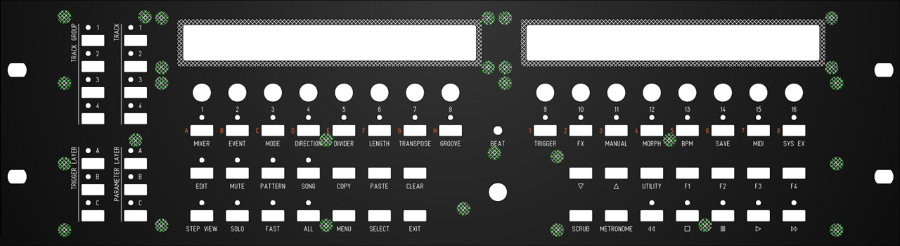
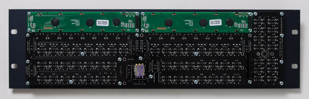
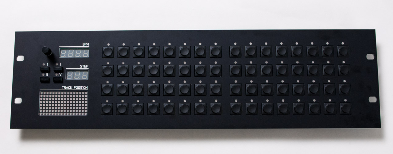
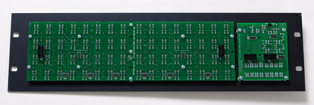
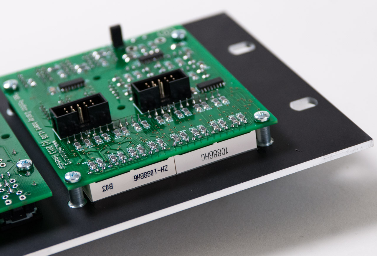
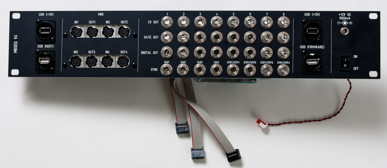
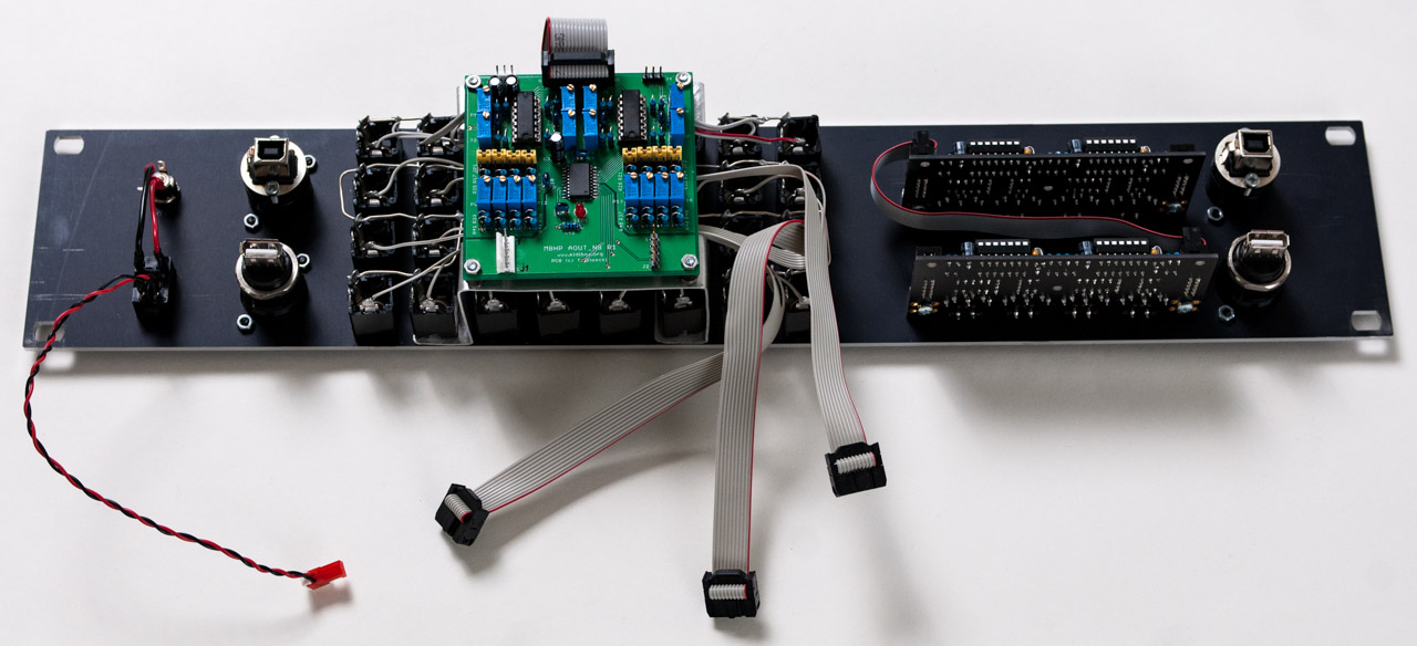
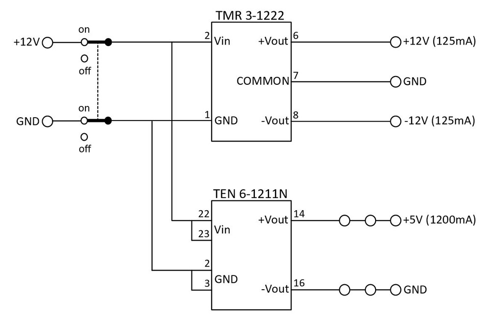
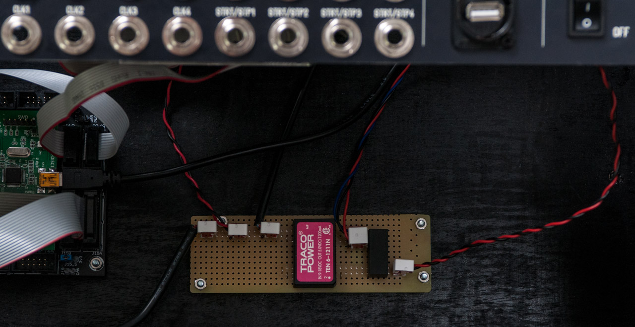
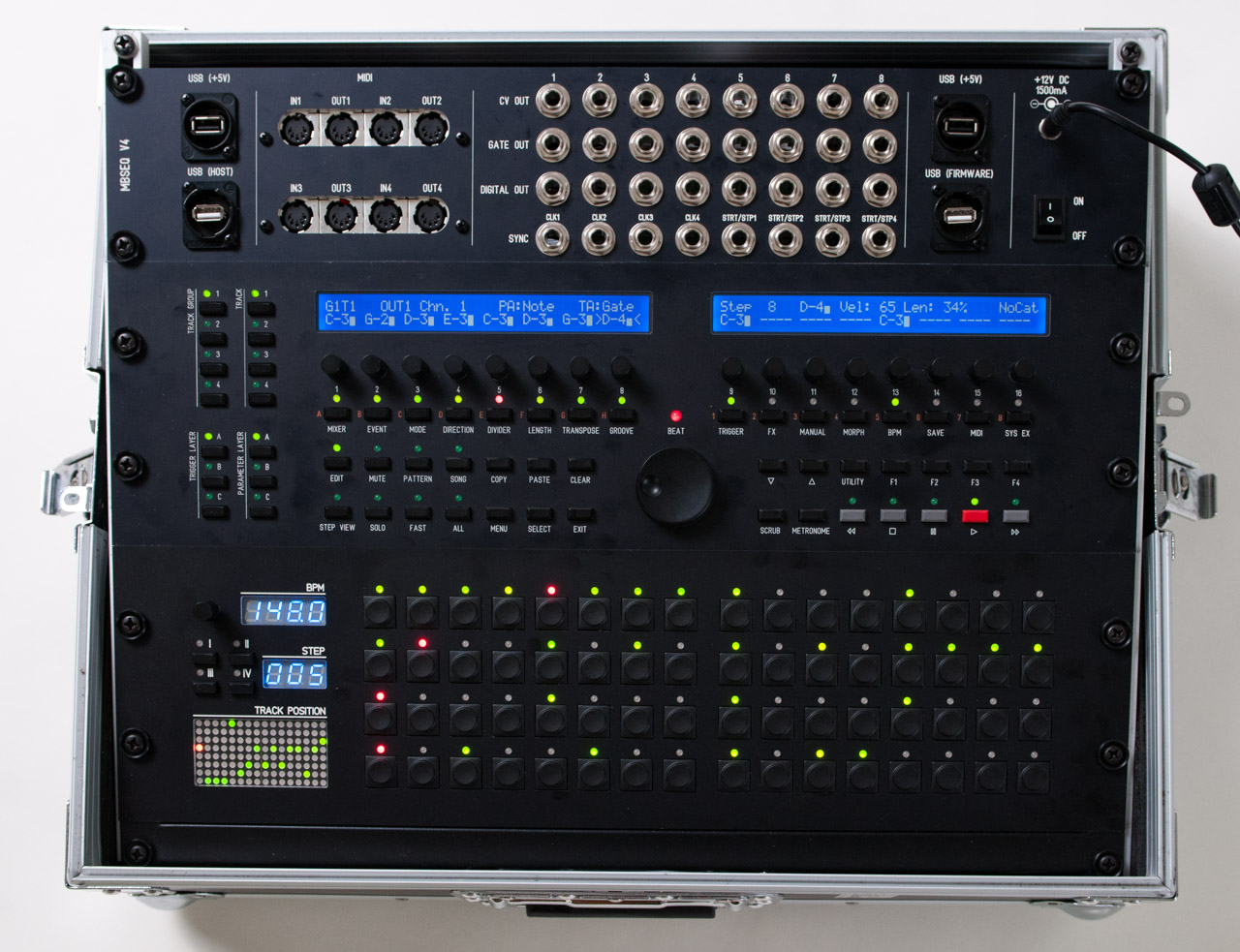
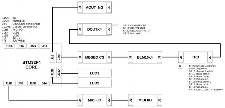
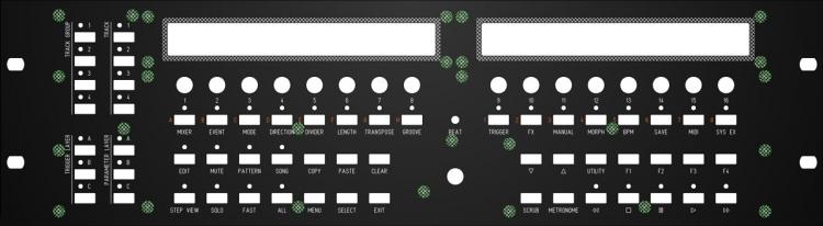
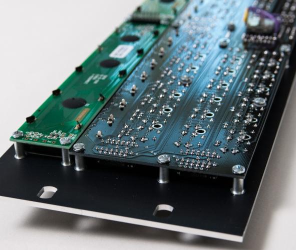
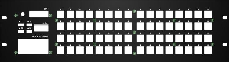
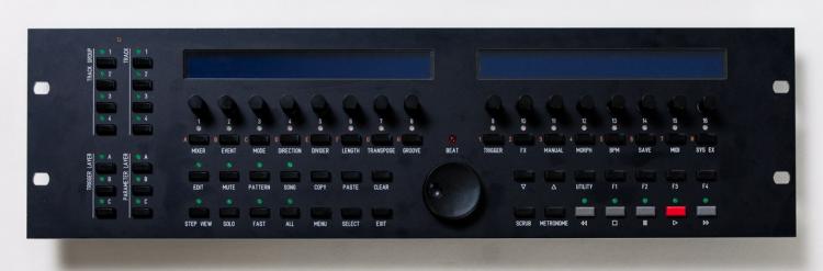
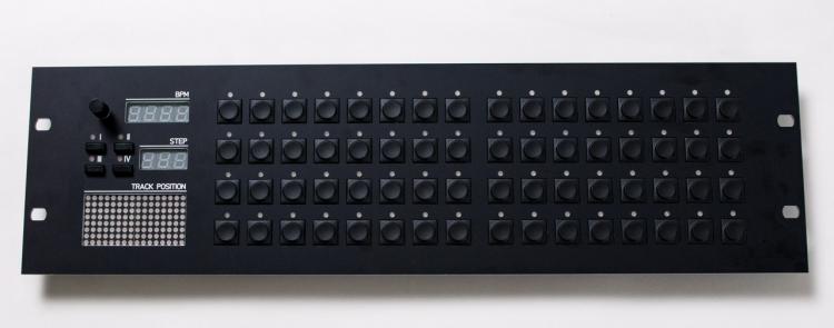
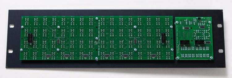
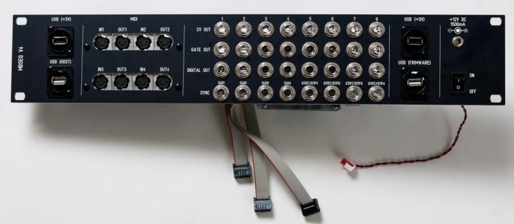
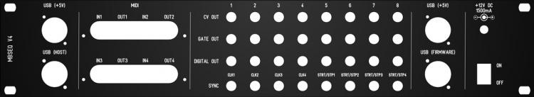
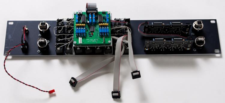
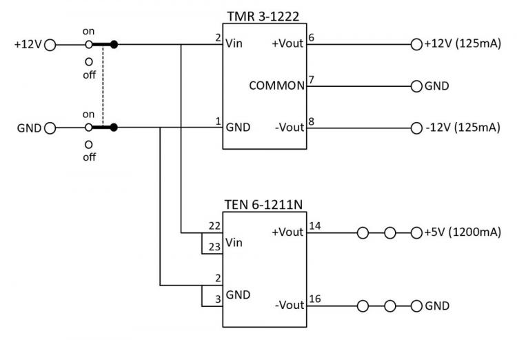
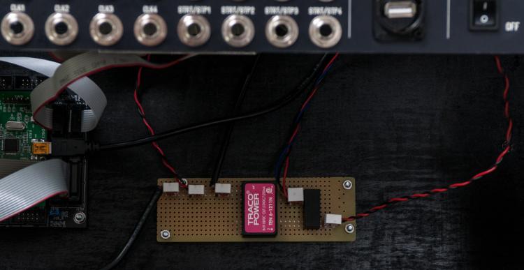
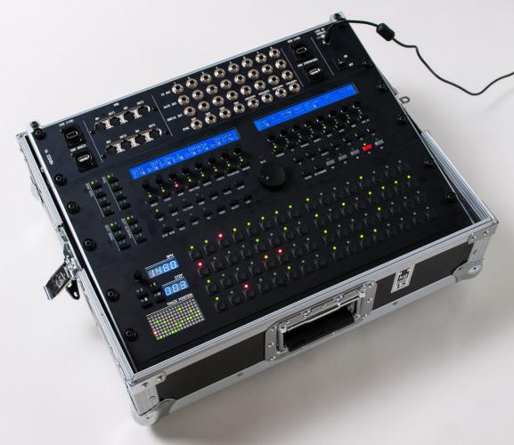
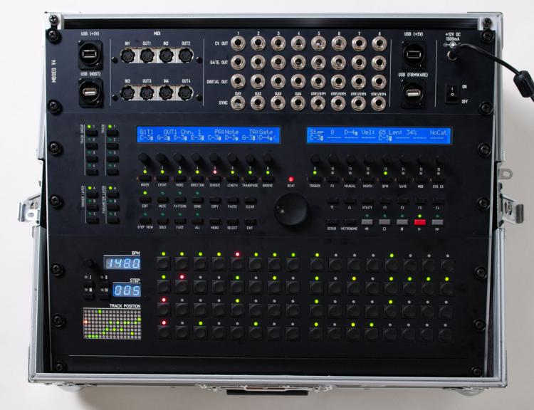
Yesterday, I finished my MBSEQ V4 build. I decided on the following components for my version of the sequencer. STM32F4CORE MBSEQ CS: Wilba Control Surface BLM16x4: 16 x 4 button matrix TPD: Track Position Display 2 x MIDI I/O: MIDI interface, a total of 4 MIDI IN and 4 MIDI OUT DOUTX4: 4 x 8 digital outputs AOUT_NG: 8 CV outputs (1V/oct) I did think about placing the digital outs and CV out modules outside of the main sequencer using line drivers so the sequencer did not have to be near the modular synthesizer. I did test the configuration and it worked as it should. However, I decided against it as I wanted the sequencer to be a self contained unit with all functionality in one box. The diagram below shows that final configuration with connections between the modules. I started with the main panel. As I wanted to house the sequencer in a 19? rack case, all panels are compatible with the standard 19? rack dimensions. I downloaded a Front Panel Designer panel design from the Midibox forum and added studs to make mounting the control surface PCB and LCD’s a lot easier. Here is my version of the FPD file: mbseq_19in_io-v01.fpd Here is a picture of how the PCB's are mounted to the panel. The second panel contains the BLM16x4 and TPD modules. For this panel I also added studs to an existing design to make assembly of the panel much easier. And here is my version of the FPD file: TPDBLM_19_v02.fpd The third and last panel holds all input and output connectors. This is a custom panel designed by myself. All I/O PCB’s are mounted directly to the panel except for the DOUTX4 PCB which is mounted in the rack case and connected to the panel connectors with flat cables. The panel also provides 2 USB +5V connectors for connecting LED lights or other peripherals. The other 2 USB connectors connect to the core PCB and provide a way to upgrade the core board firmware and the MBSEQ firmware. If I had to do it again I would leave out the labels above the SYNC outputs. This is the FPD file for the panel: MBSEQ_IO_panel_2HE-v02.fpd For the case I ordered the Thon Rack Case 8U 12 RA from Thomann. My MBSEQ V4 fits perfectly in there. There is even about 1 HE left. I used a black panel to fill that space. On the bottom of the case I mounted the core module and the DOUTX4 digital out modules. I also installed a custom PSU (DC-DC converter) which provides +5V (for the core board and the USB ports on the I/O panel) and +12V/-12V (for the AOUT_NG module). I’m very happy with the end result. The panels fit neatly in the 19? case. The 19? rack in the case is a bit angled which improves visibilty of all display and controls. Here is the final result.

-
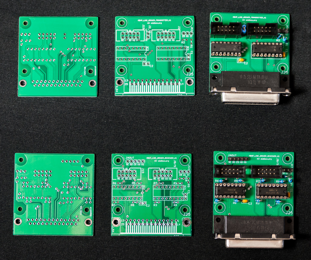
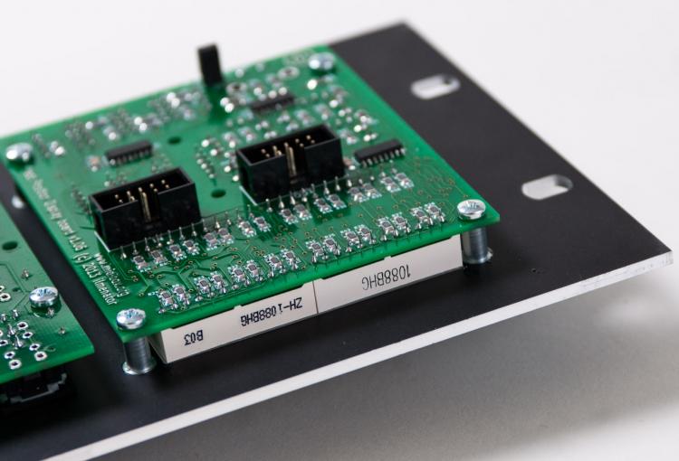
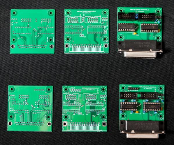
I have a few line driver PCB's left which a don't use. Included in the photo are the finished PCB's for reference. PCB's will be sold without components. A set (1 receiver PCB and 1 transmitter PCB) is €5. Shipping to most European countries is €4. If you're interested in buying a set let me know where you live and I can verify the shipping costs.
-
MBSEQ V4 config check: TPD and line drivers
beautyofdecay_ replied to beautyofdecay_'s topic in MIDIbox SEQ
A quick update as I finally tested the configuration below. Both the DOUTX4 and AOUT_NG modules were connected with line drivers. This configuration also worked fine. The digital outs worked as it should and I could switch the output voltages of all CV outputs via the CV configuration menu.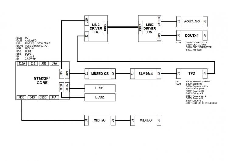
-
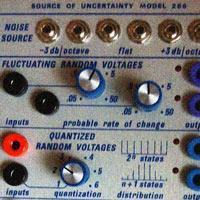
Would be nice to be able to select 1.2V/oct in the CV configuration menu. This is useful for connecting to Buchla modular gear.
-
beautyofdecay_ changed their profile photo
-
MBSEQ V4 config check: TPD and line drivers
beautyofdecay_ replied to beautyofdecay_'s topic in MIDIbox SEQ
Although I have decided against using the line drivers in my final setup I did test the line drivers with the DOUTX board today. I used the following configuration. It seems to work just fine (as ilmenator predicted ). I will also test this in combination with the AOUT_NG board but must make some cables to make that happen. I also tested this configuration without the line drivers, with the DOUTX4 board connected directly to the TPD board. This also worked without problems. Update soon!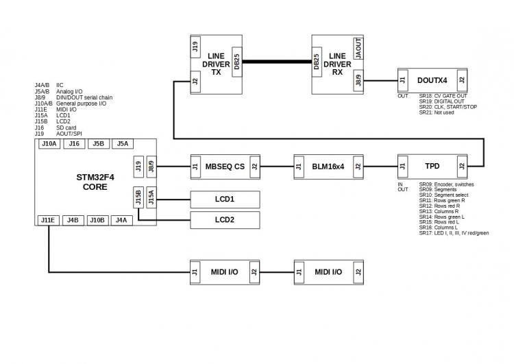
-
My reference was to the line drivers. When I added them, power consumption went up with about 300mA. The TPD and BLM16x4 were connected to the receiver side of the line drivers. I didn't expect them to be so power hungry...
-
Just to add some more info to this thread... I tested the line drivers in my configuration (STFM32F4 core, 2 x blue LCD, Wilba panel, line driver transmitter, line driver receiver, TPD, BLM16x4 and 2 x MIDI I/O) and the power consumption peaked at 750 mA. So these things really add to the overall power consumption!
-
TPD testing and configuration questions.
beautyofdecay_ replied to gerald.wert's topic in MIDIbox SEQ
Looked into the decimal point problem yesterday. It took a while before I realised that I had somehow managed to solder in a 100n cap instead of a 100R resistor for R16... After I fixed that, all worked fine! -
My MBSEQ config at the moment contains the STFM32F4 core, 2 x blue LCD, Wilba panel, TPD and BLM16x4 panel and 2 x MIDI I/O. This configuration consumes 450mA peak at 5V.
-
TPD testing and configuration questions.
beautyofdecay_ replied to gerald.wert's topic in MIDIbox SEQ
Thanks for that information! I have my TPD up and running, only problem is that the decimal point of the BPM display is not working. Haven't looked into that yet but your info definitely makes it easier. The text you see scrolling at start up is the name of the active session. My guess is in your case it is the default text when no sessions are active. Press the Exit button until you see the firmware version in the left display. In the right display you should see /SESSIONS/<your active session name> Just select SaveAs and enter the text you want. That text will be displayed in the TPD matrix display next time you boot the sequencer.