Search the Community
Showing results for tags 'tpd'.
Found 16 results
-
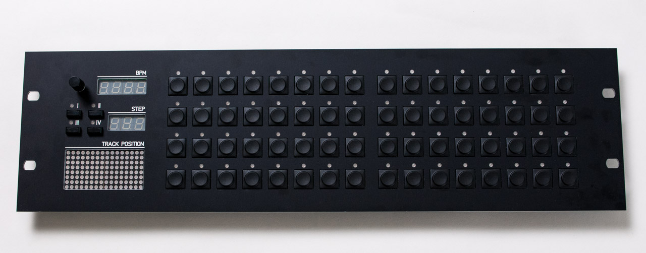
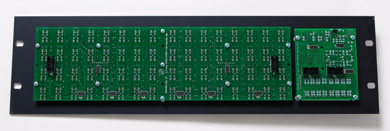
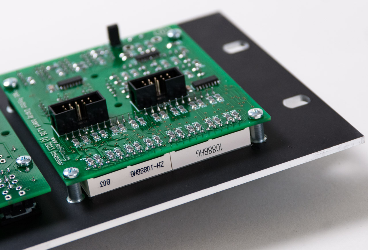
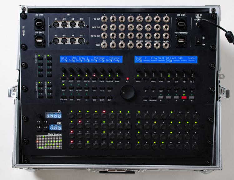
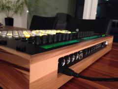
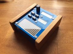 Standalone Track Position Display, which is plugged via D-Sub 9 Connector on my MBSeqV4.
 -
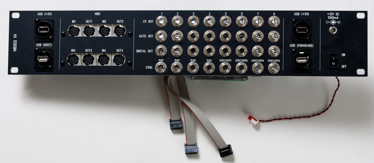
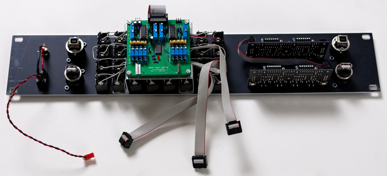
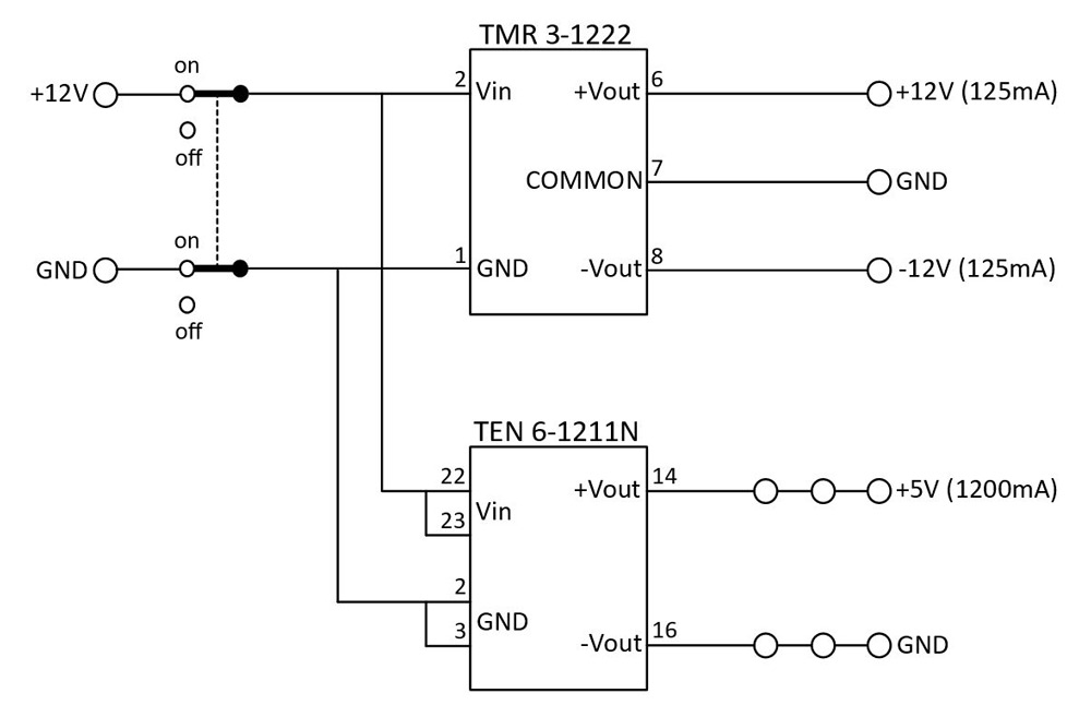
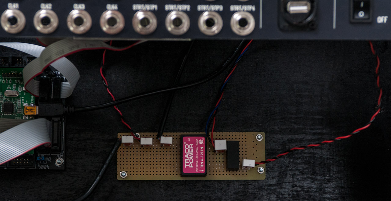
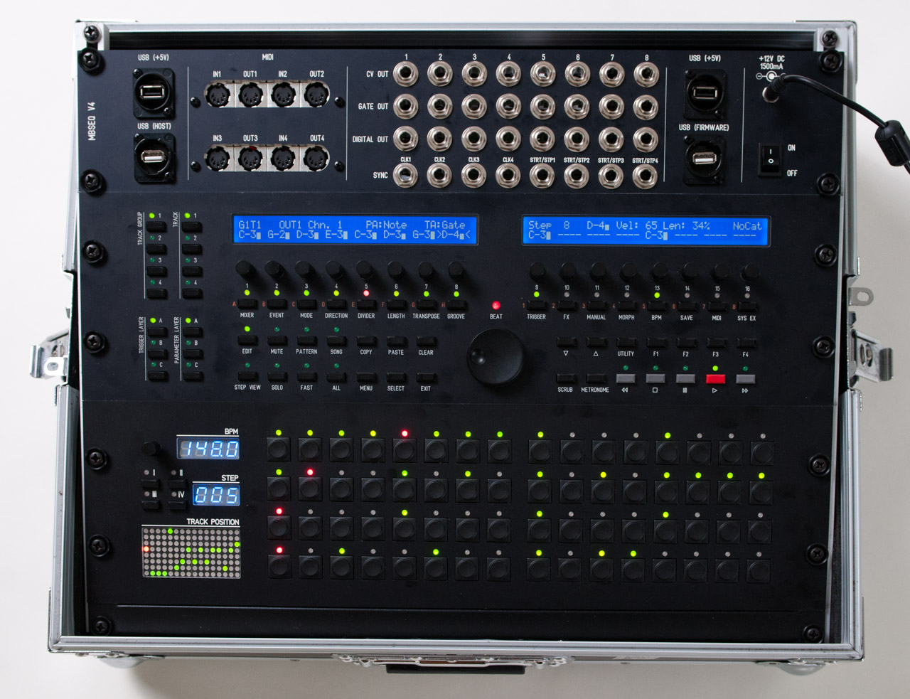
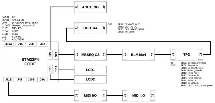
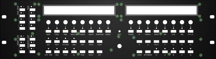
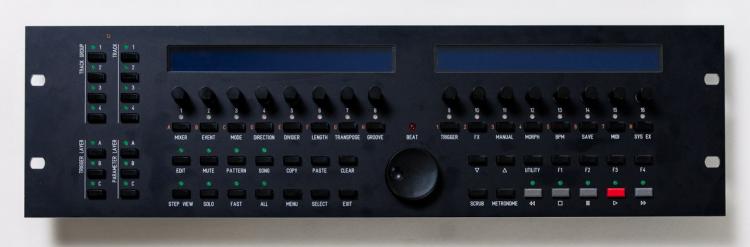
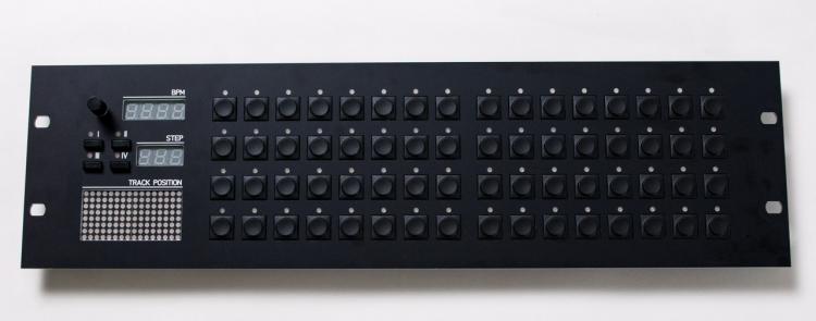
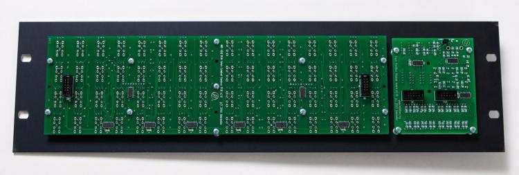
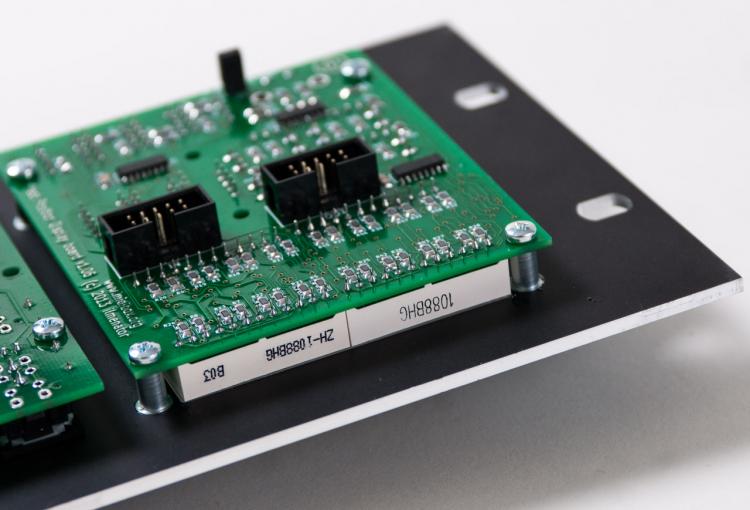
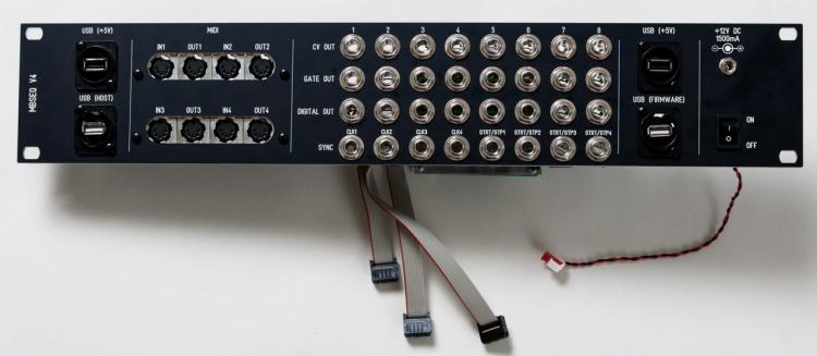
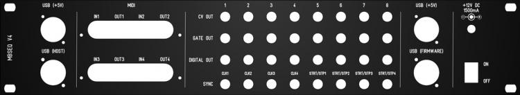
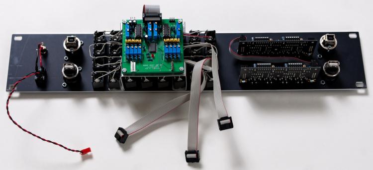
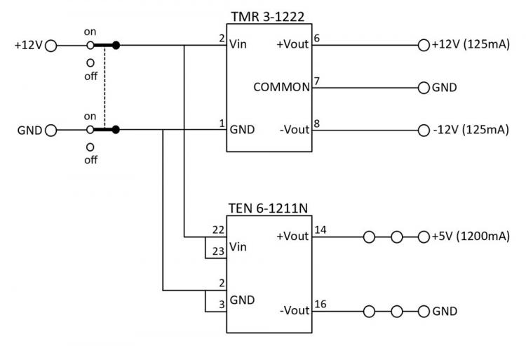
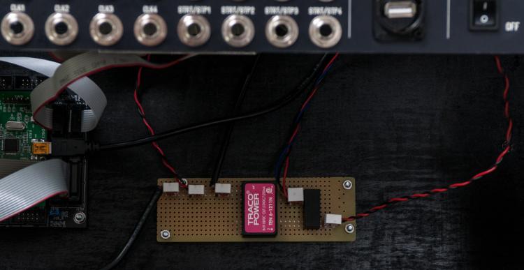
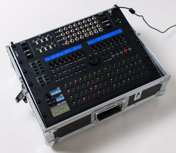
Yesterday, I finished my MBSEQ V4 build. I decided on the following components for my version of the sequencer. STM32F4CORE MBSEQ CS: Wilba Control Surface BLM16x4: 16 x 4 button matrix TPD: Track Position Display 2 x MIDI I/O: MIDI interface, a total of 4 MIDI IN and 4 MIDI OUT DOUTX4: 4 x 8 digital outputs AOUT_NG: 8 CV outputs (1V/oct) I did think about placing the digital outs and CV out modules outside of the main sequencer using line drivers so the sequencer did not have to be near the modular synthesizer. I did test the configuration and it worked as it should. However, I decided against it as I wanted the sequencer to be a self contained unit with all functionality in one box. The diagram below shows that final configuration with connections between the modules. I started with the main panel. As I wanted to house the sequencer in a 19? rack case, all panels are compatible with the standard 19? rack dimensions. I downloaded a Front Panel Designer panel design from the Midibox forum and added studs to make mounting the control surface PCB and LCD’s a lot easier. Here is my version of the FPD file: mbseq_19in_io-v01.fpd Here is a picture of how the PCB's are mounted to the panel. The second panel contains the BLM16x4 and TPD modules. For this panel I also added studs to an existing design to make assembly of the panel much easier. And here is my version of the FPD file: TPDBLM_19_v02.fpd The third and last panel holds all input and output connectors. This is a custom panel designed by myself. All I/O PCB’s are mounted directly to the panel except for the DOUTX4 PCB which is mounted in the rack case and connected to the panel connectors with flat cables. The panel also provides 2 USB +5V connectors for connecting LED lights or other peripherals. The other 2 USB connectors connect to the core PCB and provide a way to upgrade the core board firmware and the MBSEQ firmware. If I had to do it again I would leave out the labels above the SYNC outputs. This is the FPD file for the panel: MBSEQ_IO_panel_2HE-v02.fpd For the case I ordered the Thon Rack Case 8U 12 RA from Thomann. My MBSEQ V4 fits perfectly in there. There is even about 1 HE left. I used a black panel to fill that space. On the bottom of the case I mounted the core module and the DOUTX4 digital out modules. I also installed a custom PSU (DC-DC converter) which provides +5V (for the core board and the USB ports on the I/O panel) and +12V/-12V (for the AOUT_NG module). I’m very happy with the end result. The panels fit neatly in the 19? case. The 19? rack in the case is a bit angled which improves visibilty of all display and controls. Here is the final result.

-
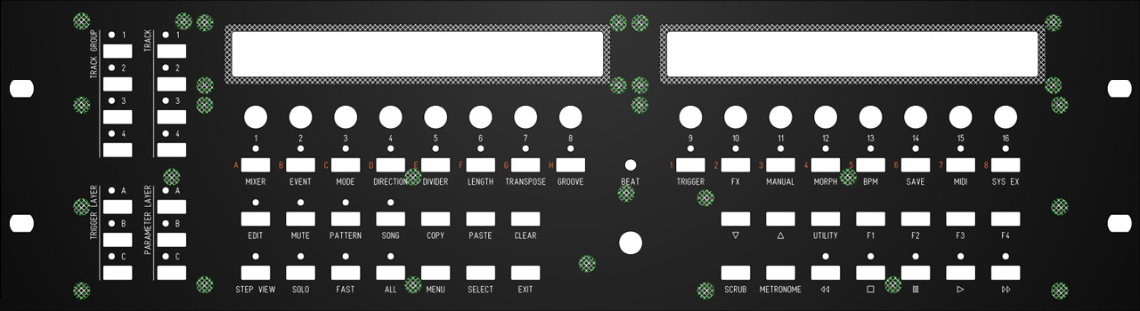
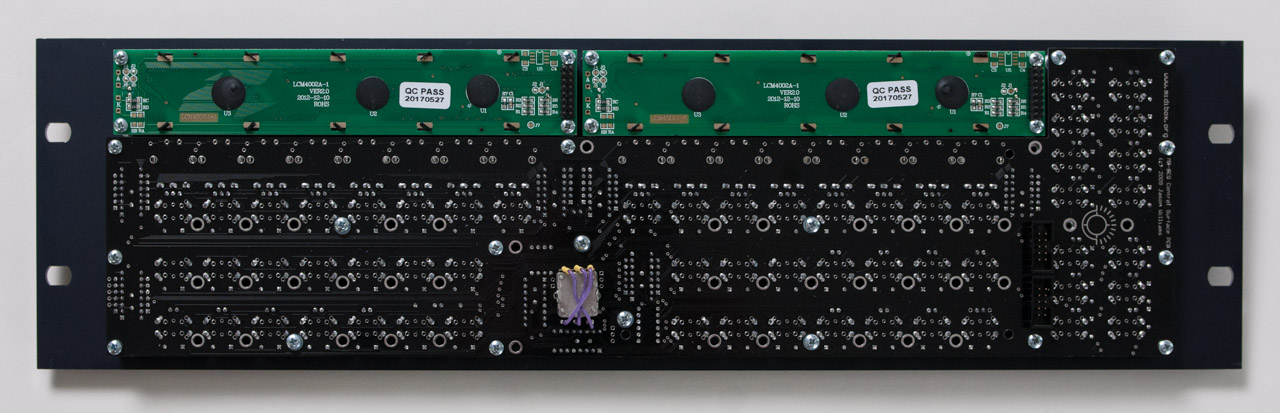
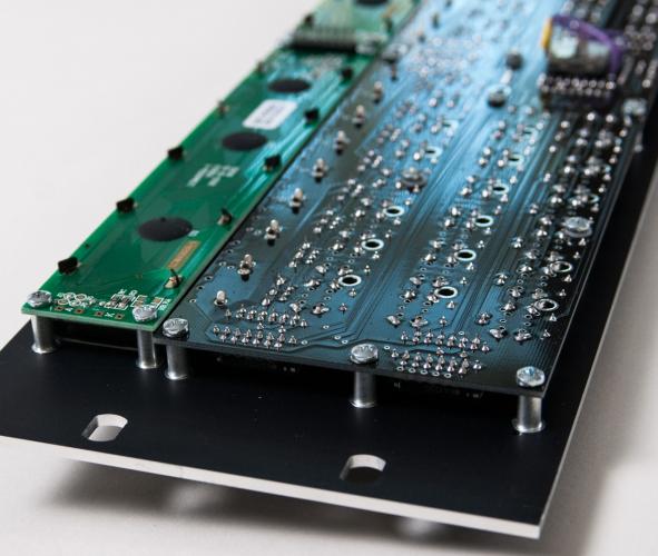
Just finished building my TPD. It is recommended on the WIKI to test everything before soldering the led displays in place as they cover several of the 595 IC. The schematic is good but there is a lot more data that would make testing go much quicker and easier. Here are the work sheets I put together to test my TPD. Hope this saves you from having to work this out on your own. The following Dout assignments are with the TPD directly connected to the core with nothing in between. This is recommended for testing as you do not have to worry with anything else if your core is good. Dout shift register chip chain order and pin counts u1 u2 u6 u7 u8 u3 u4 u5 u9 0-7 8-15 16-23 24-31 32-39 40-47 48-55 56-63 64-71 SEG SEL M2G M2R M2CA M1G M1R M1CA BiLEDS U10 is on its own DIN serial chain. DIN is easy to test just close the switch and you should see the pin toggle in the console. To test Digital Out Shift Registers from the mios console: Set dout 0 1 --> sets dout 0 to 5v set dout 0 0 --> sets dout 0 to 0v I liked turning things off as I went so only the one that I was testing was on. IC IC pin dout# led pin IC IC pin dout# led pin IC IC pin dout# led pin U3 1 40 10 U4 1 48 11 U5 1 56 12 2 41 7 2 49 8 2 57 9 3 42 4 3 50 5 3 58 6 4 43 1 4 51 2 4 59 3 5 44 22 5 52 23 5 60 24 6 45 19 6 53 20 6 61 21 7 46 16 7 54 17 7 62 18 15 47 13 15 55 14 15 63 15 IC IC pin dout# led pin IC IC pin dout# led pin IC IC pin dout# led pin U6 1 16 10 U7 1 24 11 U8 1 32 12 2 17 7 2 25 8 2 33 9 3 18 4 3 26 5 3 34 6 4 19 1 4 27 2 4 35 3 5 20 22 5 28 23 5 36 24 6 21 19 6 29 20 6 37 21 7 22 16 7 30 17 7 38 18 15 23 13 15 31 14 15 39 15 Led matrix pin out from top of board: 13 14 15 16 17 18 19 20 21 22 23 24 0 0 0 0 0 0 0 0 0 0 0 0 1 0 0 0 0 0 0 0 0 0 0 0 0 1 2 3 4 5 6 7 8 9 10 11 12 For U1, U2, U9 and U10. These IC are also not captive when the board is complete so you can get at them fairly easily. It would still be good to test everything with just the IC, caps, box header and resistors on the board. It is a lot easier to get at the ic legs with a soldering iron with the other components not in place. IC IC pin dout# led pin IC IC pin dout# led pin IC IC pin dout# led pin IC IC Pin Dev Pin U1 1 0 a U2 1 8 Step 100 U9 1 64 G U10 11 ENC1 2 1 b 2 9 Step 10 2 65 G 12 ENC1 3 2 c 3 10 Step 1 3 66 G 13 ENC1 SW 4 3 d 4 11 BPM 100 4 67 R 14 Available 5 4 e 5 12 BPM 10 5 68 R 3 SW1 6 5 f 6 13 BPM 1 6 69 R 4 SW2 7 6 g 7 14 BPM .1 7 70 R 5 SW3 15 7 DP 15 15 Available 15 71 G 6 SW4 Hope this makes your testing go much easier. I did this on paper and marked with red anything that was not working or just did not seem right. I then went back and soldered anything that needed it again then retested. I am not sure why but some of those 595 pins just do not want to take solder. Maybe I just need more practice or flux. on the encoder mine is turning backwards. I read elsewhere to set the config to the odd shift register instead of the even. I have not tried this yet but will give it a shot. Tested and I set the Encoder to 1 instead of 0 on the shift register and it is good to go now. Does anyone know how to get the display to run in the other modes? I see in the sequencer program that there are other modes but I do not see a way to alter it. Is there a pointer to the location of the text that displays on the TPD on startup? It plays "HW config v4l" on startup. I have not located it yet in the code but am looking. I looked through the TPD wiki and the seq manual but do not see anything on the above. Thanks for the great add on to the SEQ now I just need to get the panel cut for it.
-
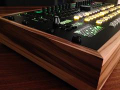
From the album: My Midibox Seq V4 incl. BLM & TPD
-
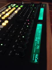
From the album: My Midibox Seq V4 incl. BLM & TPD
-
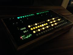
From the album: My Midibox Seq V4 incl. BLM & TPD
-
From the album: My Midibox Seq V4 incl. BLM & TPD
-
From the album: My Midibox Seq V4 incl. BLM & TPD
-
From the album: My Midibox Seq V4 incl. BLM & TPD
-
From the album: My Midibox Seq V4 incl. BLM & TPD
-
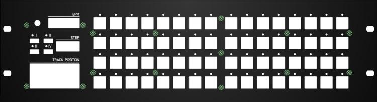
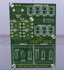
A number of people claimed interest in a Eurorack variant of my TPD, so I sat down and tried to modify the parts layout to somewhat better accommodate the Eurorack width. Here is a screenshot of the PCB. It is essentially built on altitude's advice on Eurorack dimensions, which I know nothing about... is this 14HP? So, the PCB is 100mm x 69mm (height x width), and the parts list is identical to the regular standard TPD. Also, the UI has the exact same layout, so you can use the template in the Wiki for your front panel. The mounting holes are different, though. Depending on interest, I might get a run of boards made after an initial testing of the prototype which will probably go to altitude.
-
From the album: EuroTPD v1.0
A screenshot of the newly created EuroTPD, a Track Position Display board better suited for Eurorack systems. It seems there was some interest in this. -
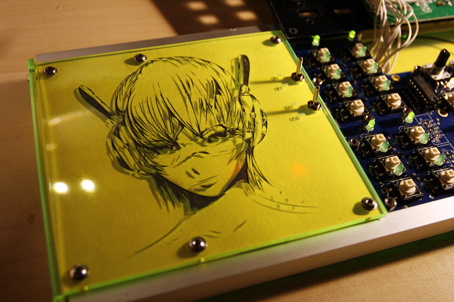
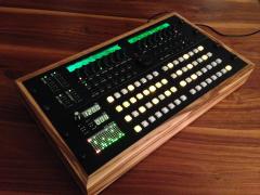
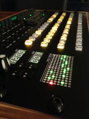
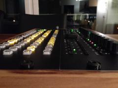
Hola, End of year holidays = build time ;-) Here is a new specialized "form factor" for a MBSEQ, that is based on Wilbas CS PCB and the new STM32F4 board. Of course, it involves a bit of DIY to achieve the flatness, some connections have to be soldered without IDC connectors, and U-shaped aluminum rails have to be cut, but no problem! :-) Tech specs: * "Slim and wide" MBSEQ V4, only 21mm high, about 70 cm wide * 40x2 OLEDs for high screen update speed and low power consumption * Pushable encoders for accelerated scrolling/note input * Battery powered for high mobility and no necessity to carry around a PSU for a jam session with friends * High quality omron tactile switches for a few million cycles (at least that is what they are advertised for) * Green transparent acrylics base and side panels for ambient light gathering and green beam emission :-) * Additional bling and functionality achieved with the TPD board :-) * Laser engraved Manga, that has been "inked" for a higher contrast :-). More pictures will be added, as the build progresses, but so far things are looking good! The battery is a 6 cell 2700mAh AA NiMh soldered pack, that can be recharged with a simple wall charger (the charge port is installed in the upper aluminum rail). A small integrated high-efficiency switching PSU converts the 6 - 9V from the battery pack down to a stable 5V. USB powered operation is optional and switchable. The battery actually lasts for many hours, i have not managed to drain it during the assembly test time, I guess it should be good for at least an evening of jamming, but maybe even 10 hours (current not measured, yet). Using NiMH and not LiPo batteries was a requirement, due to easiness of charging and battery safety. This unit was especially built for use on a MIDIfied piano. It fits perfectly on the central noteholder and after attaching just 2 midi cables, one is ready to jam :-). The amount of MIDI ports has been reduced to 4, as more is not necessary for that usecase, but an additinal four MIDI ports can be stacked on top (right side of the unit, see a picture, that is posted later on ;-)). If you are interested in the Formulor/Ponoko plans or have general build questions, say a word, and I will make them available publicly and give advice on how to build it. Hopefully, you are enjoying the report and maybe get some ideas for building a non-standard SEQ? :-) It is the best hardware sequencer on this planet and deserves some customization efforts to create a unique, personalized unit! :-) Many greets, Peter

-
Hi Guys I have one "semi kit" for sale for the Track Position display. Ponoko Laser Cut Front and Rear Panel in Transparent Acrylic PCB 2 x LED Matrix displays 7 x Kingbright 7 seg displays (I am fairly certain they are green) 1 x knob 1 x encoder 1 x 74HCT165 Buttons, switches, BiLEDS, 74HCT595, IDC header and SMD passives are missing - I simply never got round to building it up. PM me if interested. Please make an offer on PM (ideally I am looking for £30 GBP, buyer pays Postage/Paypal fees. kguy<dot>wilkinson<at>gmail<dot>com Please dont reply with offer on this page. Cheers Guy
-
I recently received a few requests for TPD kits, as some of the parts seem to be difficult to obtain in some areas of the world - surprisingly, the 7 segment LED displays were among them. Unfortunately, I cannot do complete kits now, but I have purchased enough parts for 5 "semi" kits that should help with the most difficult parts. The semi kits consist of: 1x TPD PCB 7x 7segment LED display green 2x duo LED matrix module 1x rotary encoder with switch 4x three-legged common cathode duo LED, clear or diffuse, you decide These are thought for people who are really having difficulties finding these - as I had to pay import duties to Norway you will most probably be cheaper if you can order them elsewhere. I am asking 24€ plus shipping per semi kit as above. For more information about the TPD have a look in the Wiki: http://www.midibox.o....php?id=tpd_pcb PM me or post interest here, I can ship immediately. Best, ilmenator
-
From the album: Schrabikus Midibox progress