Search the Community
Showing results for tags 'aout_ng'.
-
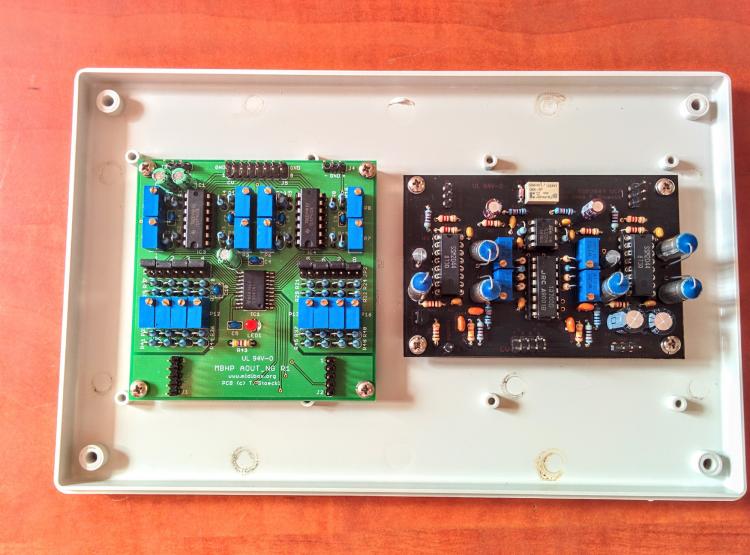
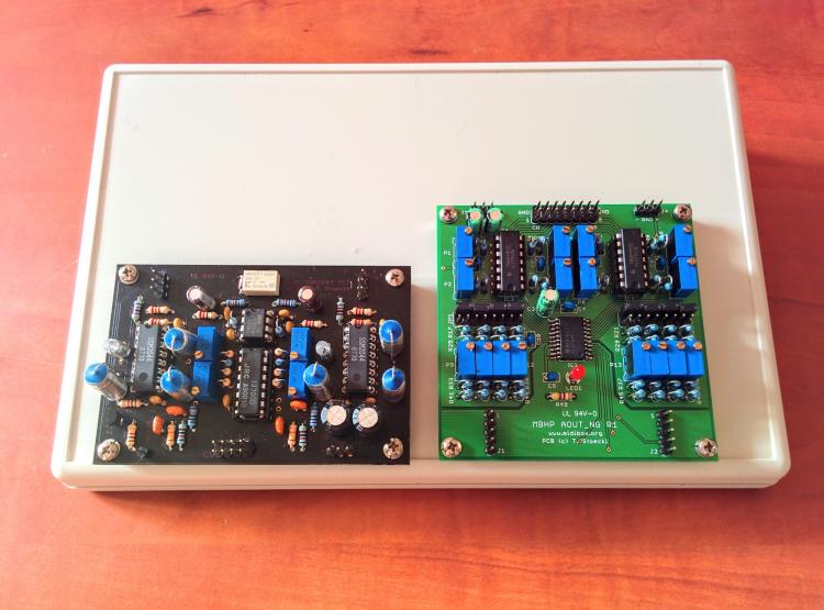
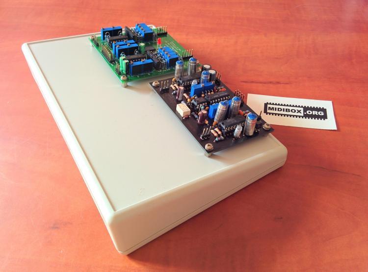
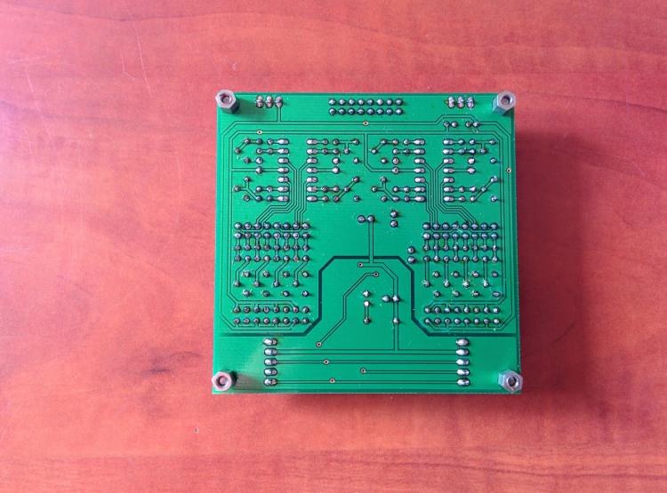
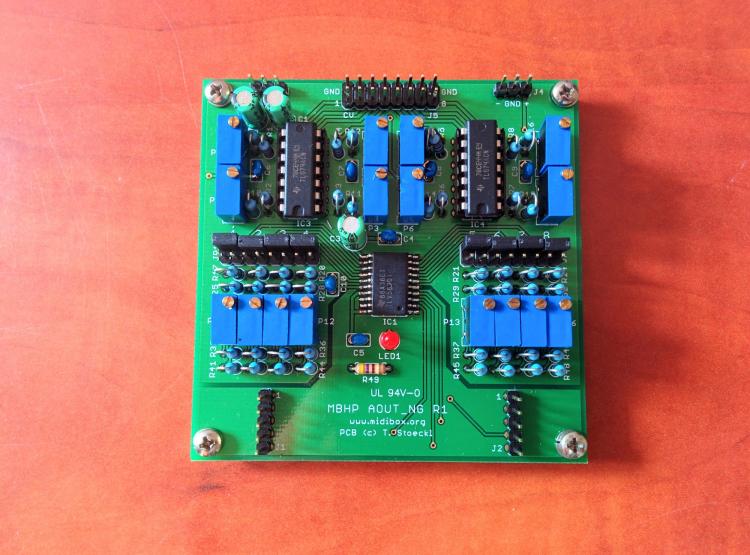
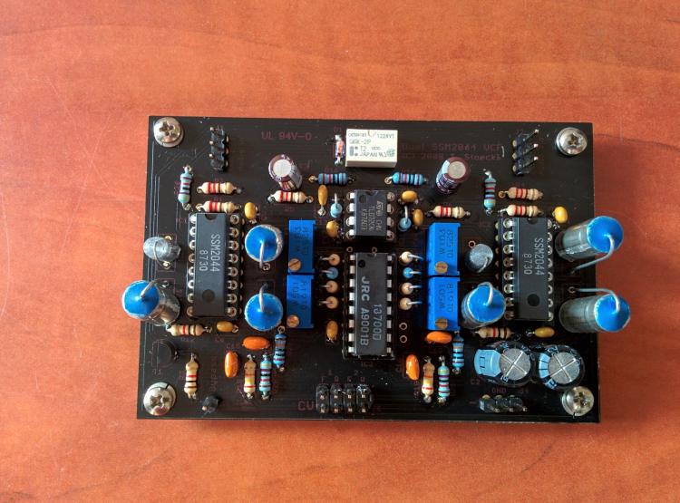
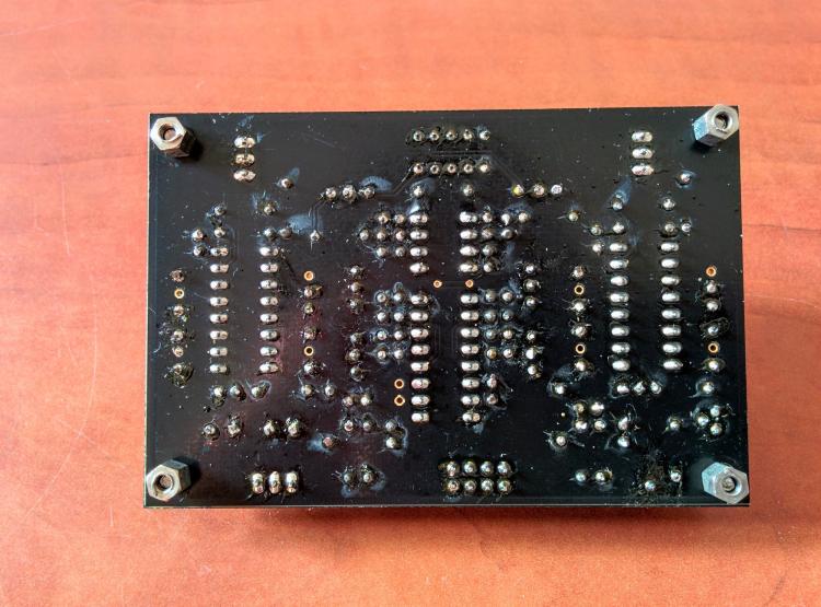
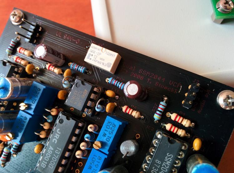
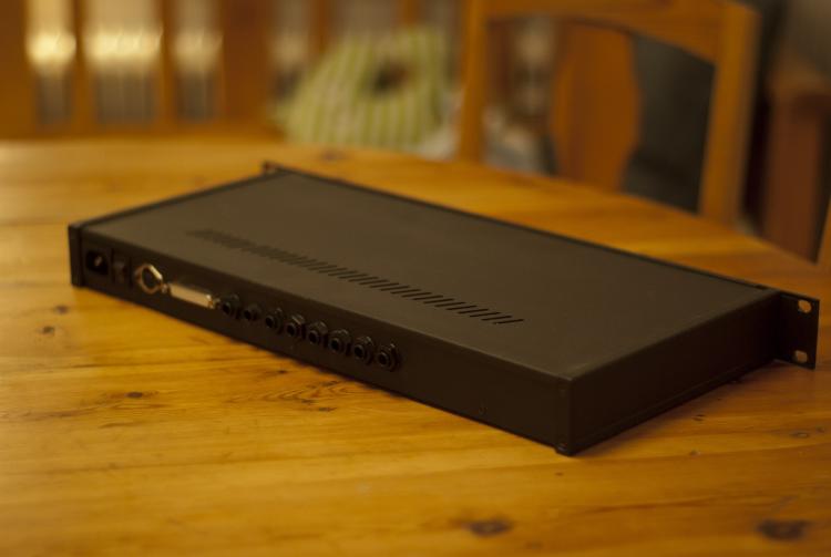
Parting ways with most of built and to be built DIY audio projects i kept over the years. Life moves on at its own pace, and my DIY audio box seemingly have been left for far too long unattended. Here's the ultra-rare, assembled and never plugged in Dual SSM 2044 VCF & MBHP_AOUT_NG module within plastic enclosure. Project link As you can see, these two uber cool stuffed boards were crafted with special attention to quality, true passion and a highest grade of perfection. These have their own character. Shipping from Canada or US at cost.
-
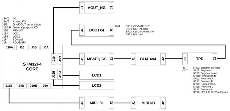
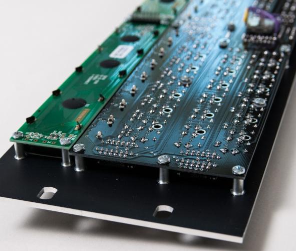
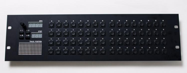
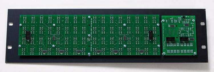
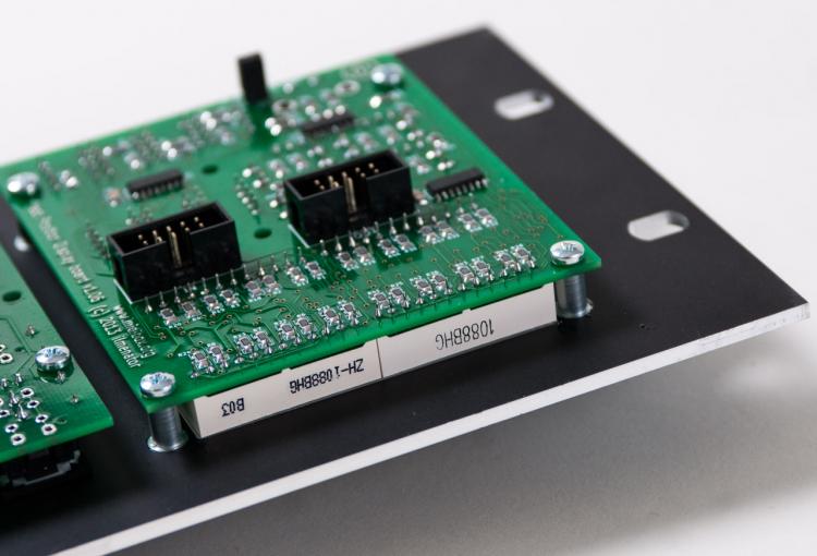
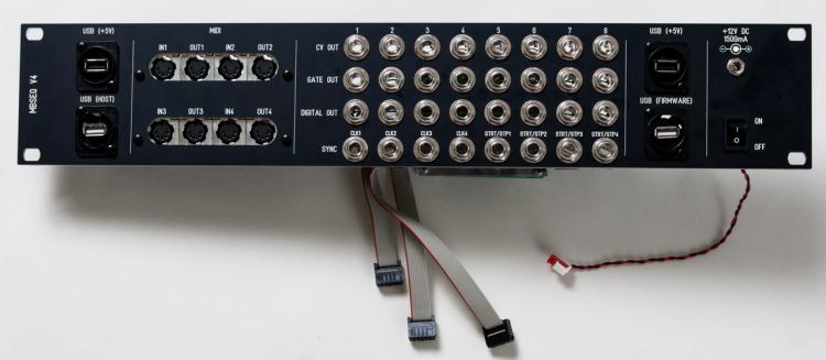
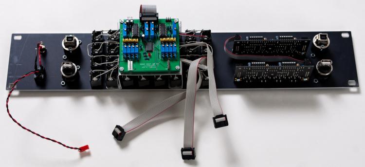
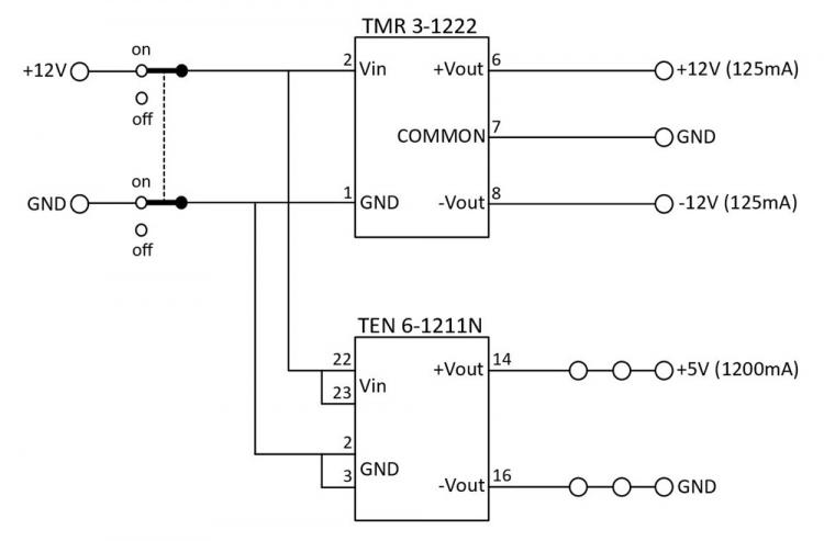
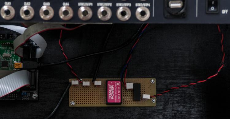
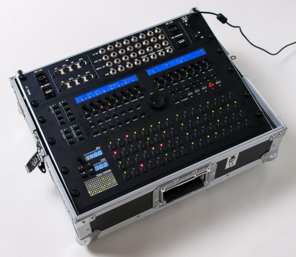
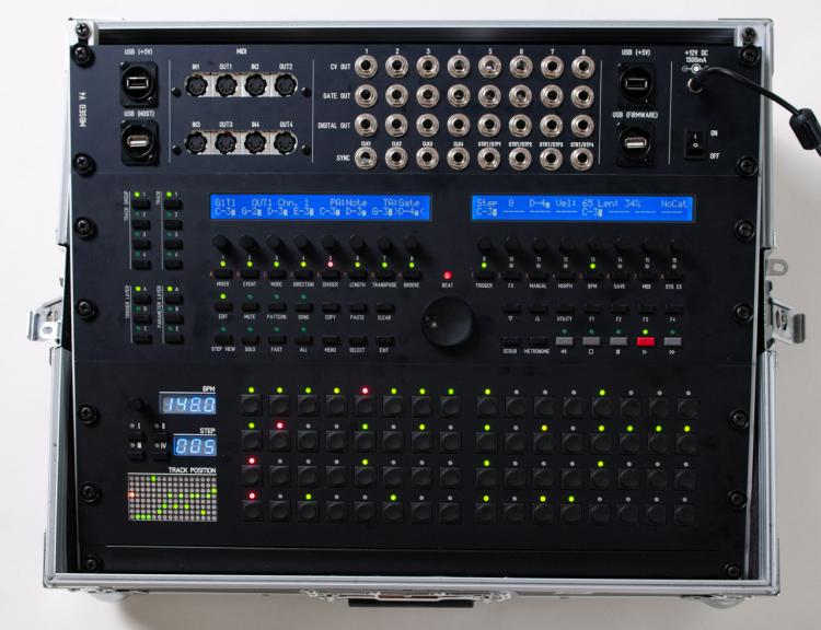
Yesterday, I finished my MBSEQ V4 build. I decided on the following components for my version of the sequencer. STM32F4CORE MBSEQ CS: Wilba Control Surface BLM16x4: 16 x 4 button matrix TPD: Track Position Display 2 x MIDI I/O: MIDI interface, a total of 4 MIDI IN and 4 MIDI OUT DOUTX4: 4 x 8 digital outputs AOUT_NG: 8 CV outputs (1V/oct) I did think about placing the digital outs and CV out modules outside of the main sequencer using line drivers so the sequencer did not have to be near the modular synthesizer. I did test the configuration and it worked as it should. However, I decided against it as I wanted the sequencer to be a self contained unit with all functionality in one box. The diagram below shows that final configuration with connections between the modules. I started with the main panel. As I wanted to house the sequencer in a 19? rack case, all panels are compatible with the standard 19? rack dimensions. I downloaded a Front Panel Designer panel design from the Midibox forum and added studs to make mounting the control surface PCB and LCD’s a lot easier. Here is my version of the FPD file: mbseq_19in_io-v01.fpd Here is a picture of how the PCB's are mounted to the panel. The second panel contains the BLM16x4 and TPD modules. For this panel I also added studs to an existing design to make assembly of the panel much easier. And here is my version of the FPD file: TPDBLM_19_v02.fpd The third and last panel holds all input and output connectors. This is a custom panel designed by myself. All I/O PCB’s are mounted directly to the panel except for the DOUTX4 PCB which is mounted in the rack case and connected to the panel connectors with flat cables. The panel also provides 2 USB +5V connectors for connecting LED lights or other peripherals. The other 2 USB connectors connect to the core PCB and provide a way to upgrade the core board firmware and the MBSEQ firmware. If I had to do it again I would leave out the labels above the SYNC outputs. This is the FPD file for the panel: MBSEQ_IO_panel_2HE-v02.fpd For the case I ordered the Thon Rack Case 8U 12 RA from Thomann. My MBSEQ V4 fits perfectly in there. There is even about 1 HE left. I used a black panel to fill that space. On the bottom of the case I mounted the core module and the DOUTX4 digital out modules. I also installed a custom PSU (DC-DC converter) which provides +5V (for the core board and the USB ports on the I/O panel) and +12V/-12V (for the AOUT_NG module). I’m very happy with the end result. The panels fit neatly in the 19? case. The 19? rack in the case is a bit angled which improves visibilty of all display and controls. Here is the final result.
-
Hi Guys, I am finaly near the end of my build of a seq4. Only need to have the Aout_ng and possible the D-out working. The D-out I will try to build on a breadboard for some extra gates and clocks. Realy looking forward for the awesomeness of controlling a modular with the midibox. Thanks again TK for bringing the AWESOME project to the public. Would you have any idea what can be the issue here with my aout_ng? Does anything below indicate wrong wiring? MBSEQ_GC.V4: "CV_AOUT_Type" and set it to 3 for AOUT_NG And on the CV Configuration Page the aout_ng is set. Core STM32F4 AOUT_NG on j19 Connected like J1:1 -> J19:Vs J1:2 -> J19:Vd J1:3 -> J19:RC1 J1:4 -> J19:SO J1:5 -> J19:SC At least I hope. No led is enabled on the Aout after booting the midibox and the DAC is not getting warm. I have only J1-j19 connected so no 12-/+ V on J3 On pin 20 on the TL5630 I got 4.5V on pin 11 as well -Aout not set in the config 4.5v on pin5, 20, 23 and 11 of the dac -Aout set in the config 4.5v on pin2, 5, 20, 23, 11 of the dac [6016.659] Setting AOUT:CS pin to ca. 5V - please measure now! 4.5v on pin2, 3, 4, 5 of the dac [6016.659] Setting AOUT:CI pin to ca. 5V - please measure now! 4.5v on pin2, 3, 4, 5 of the dac [6476.996] Setting AOUT:SC pin to ca. 5V - please measure now! 4.5v on pin2,3,4,5 of the dac Does anybody has a hint what I should check? Thanks in advance, Cheers Tim
-
I've encountered some behavior with the CV out of which I'm not certain if it's meant to be like that or not. Whenever I mute a channel outputting voltages on a CV output, the voltage stays on the last outputted voltage. When pitching a VCO this is not a big of a deal, because the gate is also muted, and so I can not hear the pitch. But if I use the CV outputs to drive other parameters (I use the CV out like an envelope of sorts) the outputs stays high. This is of course of influence on parameters that I'm driving. Some modules use the potentiometer as an offset for incoming voltage on their respective CV in. But with a voltage on the input I can not turn the control fully down. Am I missing a setting regarding CV outs, or is there a workaround to this behavior? Or is there something wrong with my setup? I would like to have a default voltage of 0V whenever a track is muted. Is this possible? Any pointers appreciated!
-
After over a year of development, I would like to start documenting my Midibox_NG project in this thread to collect as much information as possible for similar future projects. The idea is to keep all findings, questions and struggles concerning this projects in one thread to keep myself organised and to help future digital/analog synth developers. As the title predicts, the goal of this project is to design and develop an all in one box digitised analog synth, similar to the MiniMoog Voyager. The synth will be controlled solely over midi. An LPC17 with Midibox_NG running acts as the main brain to read digital pots and switches of the control panel, save and recall presets as well as to drive the synth through multiple analog and digital outputs. Analog synth hardware: 1x LFO 2x Modulation Bus 3x VCO incl. waveshapers as well as additional loops for other effects than the waveshapers (documented on: http://www.muffwiggler.com/forum/viewtopic.php?t=108794) 1x Noise generator 1x Ext_In 1x Mixer stage 1x 5Pulser (http://home.comcast.net/~ijfritz/sy_cir8.htm) 1x Ring modulator 1x Phaser effect 2x Moog ladder LP filter (to create a stereo effect through filter cutoff spacing) 1x Moog T904B HP filter (to create a band pass together with one of the LP filters (http://www.freeinfosociety.com/electronics/schemview.php?id=944) 2x ADSR (for filter and volume) 1x Stereo VCA 1x Headphone preamp 1x +/-15V & +5V switching power supply (I learned, that it is much easier to develop circuits with the additional "headroom" of +/-3V in comparison to a +/-12V supply) 1x Power board to generate +/-12V for the AOUT_NG modules as well as +10V clean reference voltage. Resources All the analog circuits are redesigned and relayouted to be uC controllable. They are mainly based on the following modules: - Ninni Bergfors' Moog based bergfotron modules (http://hem.bredband.net/bersyn/) - Original Moog D schematics (http://www.fantasyjackpalance.com/fjp/sound/synth/synthdata/16-moog-minimoog.html) - Original Micromoog schematics (http://www.fantasyjackpalance.com/fjp/sound/synth/synthdata/07-moog-micromoog.html) - Yves Usson's Yusynth (http://yusynth.net/Modular/index_en.html) - René Schmitz's modules (http://www.schmitzbits.de/) - Carsten Toensmann's Moog Modular Clone (http://www.analog-monster.de/mmschemos.html) - Vinnui's Modbus concept (http://vinnui.blogspot.ch/2011/09/concept-of-modulation-bus.html) The original idea was to use the Moog D schematics solely and as many original parts as possible. But after already acquiring many old parts for a reasonable amount of money, I dumped the idea when the last Chinese seller of UA726 remakes went off market. However, I don't regret the decision, as I am very happy with my results so far with more modern parts, which are not nearly as energy hungry as the old stuff. Midibox Hardware: 1x LPC17 core module 1x KS0108 based graphic LCD 1x SD card reader 1x AINSER64 module 1x DIO_MATRIX module 1x DOUT module (own design with partly high power shift registers for switching relays) 4x AOUT_NG modules Development Roadmap (fully implemented, partly done, not touched yet): - HARDWARE Power Board - HARDWARE Midibox modules (excl. DOUT) - HARDWARE VCO & waveshaper board (incl. trimming & tuning) - HARDWARE LP filter - HARDWARE HP filter & filter switching circuit - HARDWARE 5Pulser - HARDWARE Ring Modulator (on the breadboard and PCB layouted) - HARDWARE ADSR (PCB layouted) - HARDWARE DOUT module - HARDWARE control panel pots & switches - HARDWARE Mixer including overdrive LED circuit - HARDWARE VCA & headphone preamp - HARDWARE LFO, MOD BUS, Noise generator circuits and PCB - HARDWARE Casing - HARDWARE Phaser (planned as a seperate module, since not enough AOUTS available) - SOFTWARE Utilising AINSER64 and AOUT_NG at one port () - SOFTWARE Controlling multiple AOUT_NG modules at once () - SOFTWARE VCO octave switch option (thanks TK) - SOFTWARE Multiple rotary switches locking each other out (softwarebug ironed out, thanks again, TK) - SOFTWARE Controlling Digital switching ICs (binary input) by DOUTs (signal switching related topic) - SOFTWARE synth fine tuningrange (+/- 3 semitones, steps as fine as possible) -> solved in the analog section, without midibox assistance - SOFTWARE VCO detuning -> semitone detuning works, free detuning not implemented in MBNG) - SOFTWARE Midibox_NG menu structure -> initial work done - SOFTWARE Preset save and recall - SOFTWARE Midi control of parameters (excl. tone & pitch bend)
- 22 replies
-
- midification
- ainser64
-
(and 3 more)
Tagged with:
-
Finally got around to using an aout_ng, and after some power and wiring issues (read: I'm a bonehead), it's almost working. Problem is that the outputs are about half the expected values for each of the configuration settings/steps. Based on the previously mentioned issues, it's mostly likely the DAC, isn't it? This is the first time I've done anything board level with surface mount, so I'm a bit hesitant...
-
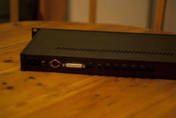
Update: The box is now sold. Hello! I have sold my MB6582 and thus have no use for my 1U rack mounted eight channel PSU/VCF/VCA expansion box. It contains : PSU: 230V input. Powers all Components in the box plus the MB6582 via a cable that fits the MB6582 power input connector. DA-converters: Four nicely soldered AOUT_NG boards control the filters and VCAs. They are controlled from the MB6582 via the expansion port. Analog filters: Four SSM2044 boards fitted with eight SSM2044 chips, relays and styroflex capacitors. Audio is fed into the filters from the MB6582 via audio jacks. VCA: Two SSM2154 boards for amplitude control of all eight audio channels. VCF output is fed into VCA input. I haven't used the box for a few years. Last time I used it everything worked well but because of all wiring, the box is sold as is. You should be able to trouble shoot if needed. I can guarantee that all boards are good though! Based on historical prices for the individual boards, I am asking $800 / €700 plus shipping and if lack of interest I will sell individual parts of the build. Any suggestions are welcome. All the best, Johan

