

NorthernLightX
-
Posts
891 -
Joined
-
Last visited
-
Days Won
1
Content Type
Profiles
Forums
Blogs
Gallery
Posts posted by NorthernLightX
-
-
Went over the schematic again and made some minor changes to the MAX525 power integrity capacitors. Also renumbered all parts to be sequential now. Just uploaded the most recent revision of all files including pictures.
PM'd TK about the CV plans for MB CV V2 and CV standards and such, and he replied he'll look into this once he has the time. :thumbsup:
-
Checkout the datasheet, page 14, figure 11.
Doesn't make sense to me at all. Way beyond my skill level. :wacko:
-
The bipolar option does not require any reprogramming. The circuitry is slightly different. But the values to be set in the register are the same as for unipolar. Just the resulting output is different.
If you feel like elaborating on this: be my guest :flowers:
I'm content with the solution I've come up with so far, but I'm Always interested in additional viewpoints :thumbsup:
-
According to the MAX525 datasheet, it can be used for bipolar operations. The internal register works a bit different then. The register is set by the software (if you compile it with the right aout module)
It is not my intention to change a lot to the AOUT module as it was. For example I don't know much (read: anything) about programming at all, so I don't want to mess up anything that is working fine at the moment. I don't want to change the schematic, just combine existing options on one board.
I tried some changes on the board layout last evening, most of which didn't work out very well. I slept a night on it, and came to the following standpoints:
CV outputs:
A DIL connector for the CV outpunts is not possible without laying out the board from scratch again, and even then I think it would be very hard (unless you want to have the CV outputs not sequentially placed on the pins - an order of 2-1-4-3 could be possible but I don't like it that way). A single 9 or 10 pin SIL connector for the CV outputs with a sequential order is not possible either. Both of the above options also don't match the philosophy of the "split" redesign.
Two 5 pin SIL headers on the other hand are possible by changing the orientation of a few resistors. I like this option and have incorporated it in the last revision (not yet uploaded). :thumbsup:
Power:
I've moved the 4 pin SIL header closer to the molex connector. :flowers:
Bipolar or Unipolar:
This was the hard part. First I thought about abandoning the bipolar option on the board and just make it unipolar - adding a bipolar option after the calibrated control voltages leave the opamp is not much harder than doing it in between the DAC and the opamp. The part cost is about the same as well. Making it like this could also be an option for the existing AOUT, AOUT_NG and AOUT_LC modules. Removing the bipolar parts from the board resulted in a lot of unused space, but moving the parts closer together did result in a mess of traces to get the CVs to the edge of the board. This also resulted in the impossibility of adding the opamp based bipolar option to the board. :sad:
Then again, it's entirely possible to leave the voltage devider/summer based bipolar option on the board, and just not populate it. Soldering 8 bridges in place of the 8 resistors in the CV signal path will make the output standard unipolar. It is a less elegant option than what the AOUT_NG has with the jumpers, but that option has a flaw as well as the proposed resistors are different for bipolar and unipolar operation, so changing the jumpers is not enough; re-calibration is always necessary.
With the soldered bridges I proposed you have no simple otion to change the operation from uni- to bipolar. You'll have to decide which channels will be bipolar and which will be unipolar when building the module. Changing your mind later is possible but you'll have to desolder parts; replace the bridges with resistors, and probably change some other resistor values as well (and of course re-calibrate afterwards). This is still the best option in my opinion.
It's also still possible to add an opamp based bipolar option to existing designs with an extra piece of (vero-)board, the schematics mentioned in this thread should be enough for experienced builders to get started. As soon as I'm going to build the SSM filters I will revisit the idea of the opamp based CV changer to have the modules respond to +/-5V on both channels.
Thus, the only thing I still need to know is how the resistor values for R_x and R_y should be calculated with the voltage devider/summer based bipolar option. Can anyone please give me a an assist? I'll score the point if you let me :D
-
The MAX525 has an external reference on the board. The Original AOUT module has both unipolar and bipolar modes, bipolar is an extension that is currently placed between the DAC and the opamp.
So, I guess a poll is in order; Bias the DAC output before or after the opamps? :phone:
-
As I was reading the schematic of the Tellun Dunsel something else came to mind: Maybe the -5V level shifter is a better bipolar option than the way it is done now.
Currently the DAC output is biassed before it hits the opamp. This causes resistor values and calibration to be off when someone wants to switch between unipolar and bipolar. What would happen if we would just let the AOUT output only unipolar signals, and bias them using a -5V shifter afterwards (on modules that need a bipolar input)? To me this sounds better than making an unipolar signal bipolar and then shifting it back to be usable.
Again: am I overlooking something?
-
full wave rectifier
OK, I was skipping it before because normally a full wave rectifier (the one using 4 diodes) just converts AC to DC (*1,4) and that's not what I was after. I'll look into the schematic of the tellun module - tellun designed a lot of good stuff :cool:
[edit]
OK, the full wave rectifier uses diodes as well. The schematic snippet you posted uses already half-wave-rectified signals (the HWR takes place in a previous stage of the module).
The Tellun Dunsel schematic however does contain exactly the thing I was after: the A+5 schematic. I just need to replace +15V through 300K Ohm with +5V through 100K Ohm for a +5V supply (right?), and place the part where A gets inverted to A- before it bacause it expects an inverted signal.
...man I'm really beginning to understand this shiz. :D
-
Ah, now it's starting to make sense; the clamp thing is used to DC offset an AC voltage, we want to offset a voltage that's already DC!
OK, I'm going to quote a few lines and ask more questions if you don't mind :angel:
Errm, I think that's over-complicating things. Why not just use an non-inverting mixer where you add or subtract 5V?
You can use a stable precision +-5V reference if you're really picky, but that's overkill IMHO.
No a precision 5v is not necessary, the standard 5v of the PSU will do fine. I was only concerned about the diode voltage drop mentioned earlier.
Something like:
CV In->100k (R3)
5V offset->100k (R4)
R2=100k
100k (R1) plus 22pf cap across (in parallel) to prevent oscillation in the feedback connection
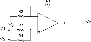
vo =v1 + v2 (for all resistors equal)
vo = (R1+R2)/R2 (v1 R4 + v2R3)/ (R3+R4)
This makes -5V become 0V, +5V becomes +10.
By adding a -5V you can go the other way.
Looks nice and simple.
Or, you can use an inverting mixer plus a unity gain inverting op-amp to make this less impedance sensitive at the cost of more op-amps used.
This makes the circuit look like this:
followed by a standard inverting op amp.
Is impedance an issue in a modular synth? I don't mind using another opamp, a dual opamp is still only a DIP8 package.
By the way the inverting mixer looks a lot like the "control summer" for the frequency CV from the SSM2044 datasheet, only here there is no extra inverting opamp to change the signal back to its original phase in that design?
For the mixer you only need to worry about op-amp offset (a small problem) plus the badwidth product of the op-amp.
Could you perhaps elaborate a bit on the opamp offset and the bandwidth product you mentioned? How much influence is expected?
-
Errm, I think that's over-complicating things.
Don't get me wrong; I'm very grateful that you provide input, but according to the stuff I read yesterday the voltage clamp is not complicated at all, and it uses less parts than your suggestion :wink:
Look at this picture: http://en.wikipedia.org/w/index.php?title=File:Precision_op-amp_clamp.svg&page=1
I see one opamp, two resistors, a diode and a capacitor. Or am I missing something?
-
However, uni- to bi-polar: Can't you just add or subtract an offset depending on which way you convert? The slope at 1V/Oct should be the same no matter what.
Yes, I found that a "Positive voltage clamp circuit using an opamp" is what we want; this will act as a voltage doubler and force the signal at or above 0v. The opamp part is because is introduces percision over the standard diode clamp, which suffers from the voltage drop of the diode.
Again a bit of theoretical knowledge without knowing the how to apply it in practice. Wikipedia has an article about it but I still don't know which value of components to choose :pinch:
Link to the article: http://en.wikipedia.org/wiki/Clamper_(electronics)
Thanks for adding the 4 pin SIP header. I am concerned it is too close to the neighbouring IC though
I will move it a bit just for you :flowers:
I would either use a 9-pin (or 10 if that is unavailable), or more likely an 8x2 header with the 8 unique pins together
OK, you're the second one to ask for it, I will see if it's possible. A quick look at the traces tells me that for 6 of the 8 traces it's not a big problem, but the devil is in the details (or in the last traces, so to say)
Will try this today and upload my results.
-
In the mean time this post on MuffWiggler implies that conversion from bipolar to unipolar and vice versa is possible. Back onto the waves of the interwebz to steal me a schematic, harrrr! :pirate:
-
I'll take 2 MB6582 windows and one MBFM window.
I am a little curious why the windows for MBFM and MBSEQ are different; they are both for 2x40 LCDs? Or did the cutout for the MBSEQ get different dimensions?
-
Iploaded new versions of all files; added a 4 pin header for power. Shuriken can use it to mount a standard 4 pin connector, ilmenator can use it to chain power :flowers:
Any other comments?
I still need proper resistor values for R_x and R_y in the bipolar mode :whistle:
-
Another addition today:
1V/Octave Unipolar is the Roland standard
1V/Octave Bipolar is the Moog standard
Hz/V is the Korg standard
This clears up things for me a lot. I don't need/want interoperability with Roland gear, Moog is enough for me. If someone wants to use the Unipolar mode there are already 3 other options available so I will not add an option to switch channels to unipolar mode to the proposed board.
Next up is investigating if Seppoman's module can be enhanced by external circuitry to adapt it to proper +/- 5V operation for both channels, but that is another topic, this one was about the proposed AOUT changes.
Any other comments about the proposed modules is still welcome!
-
Some info from a post on MuffWiggler (great forum about modular synths, I've seen some familiar names from the Midibox forum over there as well)
CV signals vary depending on the format of the modular, and the function of the specific module. For example, in Euro modules it is generally safe to plug any signal in the range of +5 to -5 into any input (there are a few exceptions, on poorly designed modules). The CV input, while accepting +/-5 might react to the full range of that signal, or in some cases might react only to +/-2.5 volts. Or in some cases might react only to 0 to +5 volts.
So in the end there is no real standard in CV land.
The next thing I need to ask myself is if I want to go through the hassle of adapting Seppoman's SSM2044 filter for proper CV response (per default it responds to +/- 2,8V (the design flaw mentioned earlier) for frequency and +0/+10,67V for resonance, and it lacks the control summer and manual controls I would like to have). An other option would be to go for a different design that used the SSM2044 chips, but I have a feeling that Seppoman's design is very nice in a fashion; for example the CV controllable resonance.
To adapt the inputs of Seppoman's SSM filter to both respond to +/- 5V external analog circuitry could be the answer. I suspect for the Frequency the +/- 5V could be tuned down to +/- 2,8V easily (voltage devider?). I don't know at all if converting the +/- 5V to +0/+10V is even possible, is it maybe possible to "bias" the CV with a +5V source from the PSU? The control summer and manual control are no more than a formality; the schematic is in the datasheet and manual controls could be added with a potentiometer that has +5v on one side and -5V on the other.
Disclaimer: most of the terminology I use I have only read or heard elsewhere, I do not fully understand the principles behind them (I should have paid more attention in school :sweat:). The voltage devider and bias for example are terms of which I only vaguely know the function.
I do think however that more people could profit from this information once it is worked out, and with Midibox CV V2.0 under development proper interfacing with the modular synth world is something to consider.
-
More info on Control Voltages (this time from the Midibox CV page)
- 1V/Octave: the maximum voltage should be 10.67V. This value is derived from the available number of notes (128): 10.67V / 128 = 0.0834V, an octave consists of 12 semitones -> 12*0.0834V = 1.00V
MBHP_AOUT_LC users have to calibrate the offset first: select "Min.", and adjust the offset trimpot until the CV out reaches 0.00V
Thereafter select "Max." and adjust the gain trimpot until the voltage reaches ca. 10.67V
Now doublecheck the gain: select 1.00V, 2.00V, 4.00V and 8.00V and adjust the gain until the selected values are reached as good as possible. - Hz/V: the maximum voltage should be 10.24V. This value has been choosen to simplify the calculation of the required voltage levels for each note. With 10.24V and 12bit resolution, each DAC step can increase the voltage by 0.005V.
Important: first go into the "Output Curve" page and select "Hz/V", otherwise you will measure the wrong results. This curve has to be selected for each CV separately which should use this characteristic.
Thereafter go into the calibration menu, adjust the offset (if required), select the maximum voltage, adjust the gain until 10.24V is reached, then try 1.00V, 2.00V, 4.00V and 8.00V - Bipolar voltages (e.g. -5V/+5V): some synths require a bipolar voltage to control sound parameters like Finetune, ADSR, CutOff/Resonance, etc.
Users of a MBHP_AOUT module need to add the Balanced CV extension to each output in order to get the possibility for adjusting the output voltage below 0V
An offset trimpot is already available on the AOUT_LC and AOUT_NGmodule.
In order to calibrate the balanced CV, first select "Middle" and adjust the offset trimpot until 0.00V is reached. Thereafter select "Min.-" and "Max." and change the levels there by adjusting the gain trimpot. Check the "Middle" voltage again and iterate, until you've found perfectly matching settings.
This does still not answer my question of what control voltages are used most of the time, but I have often read about 1v/oct so I'm assuming this is more or less the standard. How many (3rd party) modules actually use a bipolar CV? (I'll investigate this further myself, but any info is welcome).
- 1V/Octave: the maximum voltage should be 10.67V. This value is derived from the available number of notes (128): 10.67V / 128 = 0.0834V, an octave consists of 12 semitones -> 12*0.0834V = 1.00V
-
Well i quote:
BTW to all SSM2044 builders: The module is designed with this (wrong) bipolar range, so you don't need to change anything on your AOUT_NGs. I guess for proper +/- 5V operation I'll have to try out a few other resistor values on the SSM module, but this will only apply if you if you're using a different CV source than an AOUT_NG.
So he's specifically talking about the AOUT_NG, which makes sense as Seppoman (T.Stoeckl) designed it. The older AOUT (MAX525 based) design comes from TK.
I know Seppoman's real name; I have communicated with him before. He does not reply to PMs anymore though, so I guess he's too busy with more important stuff. I guess he got swamped with questions about his filter by n00bs like me.
I was referring to this part of his post:
And BTW2: I've just had a short look at the old/original AOUT, and the bipolar mod is the same concept like what I'm doing on the NG (guess that's where I got it from ;)), so this module will probably show the same behaviour.
Apparently the resistors of the bipolar mod half the voltage coming out of the MAX525, that needs to be taken into account. Hence my question. The calculations you are doing are explained in the Original AOUT PDF, I can do those myself (but thanks anyway :flowers:). I'm going to look into the bipolar mod now and see if I can come up with a similar formula. Would it perhaps suffice to just half the reference voltage of 2.048V in the calculation?
:pinch: Overlooked the fact that it is a trimmer. And you are right, 510 Ohm is not a valid value for a trimmer. This should be correct then: R_x at 3,9K, R_y at 2,7k and R_p 500
You would then have a adjustable range from 4,544 - 5,006V or use R_x at 4,1k then range would be 4,67 - 5,15. Last one is probably better.
For the standard unipolar mode you are right (but the standard suggested values give a better spread), for bipolar I'm still not convinced you're not overlooking something :blush:
-
Power connectors seem to be a bit bulky for so little current (why not use regular white pcb connectors?)
I wanted to use a molex connector (the kind you find on IDE harddisks) on the PCB, as I'm going to use those for more modules in my synth. I guess adding a 4 pin connector the size of a SIL pin header is not too hard if there is demand.
I am pretty sure Seppoman's comment only applies to AOUT_NG (See this from TK)
Seppoman's post was about the addition of the bipolar option influencing the resistor behaviour of R_x and R-y, also on the Original AOUT, hence my question. If the AOUT is not influenced by this, that's an answer to my question. Are you really sure about this or is it still an assumption?
As for the resistor values you want to end up with a range of -5/5V. To do this you need a value of 1,44140625 (5V /2,048 -1). With R_x at 3,9K, R_y at 2,2k and R_p 500, you'll end up with 5,006. Which has an overshoot...So you use R_p value of 510.
Are these ideal values for the bipolar option? R_p is a 500 Ohm trimmer, what trimming range will your suggested values provide? Please excuse my ignorance... :whistle:
I would probably chain the power connector, so that there is an in and an out connector on the PCB. A simple SIL header would probably do fine.
I will be making a power bus board for my synth, so daisy chaining power is not important for me. Where would you chain the power to? Is a bus board perhaps a better solution for you as well?
And for the CV outs, it might be nice to have an additional DIL connector? Not sure if this would be feasible though...
It was very hard to route the CV traces the way they are now, and the dimensions of the current board are the maximum that free Eagle will allow. I don't think a DIL header for the CV outs is possible. I will use jacks on the frontpanel to patch the CVs to their intended destination, so 2-pin connectors are fine for me.
More general questions:
Now, I still do not understand why some modules need bipolar and others don't, or some modules even use both at the same time for different functions (Seppomans SSM filter for example). Will a bipolar CV work with all CV devices, or are there devices that will only work with unipolar CV? I mean CV devices in general (for example Moog modules), exceptions can of course exist.
I don't mind adapting the CV inputs of additional modules to comply with one standard, I thought the -5 / +5v to be a good standard to use, or am I incorrect? Additional reading about CV voltages and standards is much appreciated. :flowers:
-
The only thing I can come up with is that you maybe have your buttons oriented at 90 degrees of how they should be. There are no frontpanel schematics publicly available as far as I know, but this file comes really close for the frontpanel at least: http://www.mb6582.org/plans/MB-6582_CS_PCB_Color.pdf
I hope you can check your button orientation with that file. Take another look at the orientation of the diodes too, a special remark has been made about them in the troubleshooting guide here: http://www.midibox.org/dokuwiki/doku.php?id=wilba_mb_6582_control_surface_construction_guide. If everything works over MIDI, and your encoders work as well, it can really only be your buttons and/or diodes (as the encoders use the same DIN registers).
[edit]
addition; on the CS PCB all encoders are routed to the right 4 flatcables and all buttons to the 4 to the left. You could also check your flatcables, and maybe interchange some shift registers. Trace the working encoders to a working shift register and try that one in the place of one for buttons that doesn't work now.
Good luck!
-
Hello everybody,
Lately I am busy with how I will connect external filters and stuff to the MB6582. I have a stash of MAX525 chips and want to use them, and these DACs perform slightly better than those of the the AOUT_NG. For my purpose I would need the bipolar option, which by default is not on the Original AOUT board. I began designing an add-on board for the bipolar option, but soon found out that there is no easy solution of interfacing anything to the AOUT board. :wacko:
I also found out that the Original AOUT board could be split. This is useful when interfacing it with MB6582; this way every core gets 4 analog output channels, 2 for each SID, for example for Cutoff and Resonance. You need 1 AOUT module per core, and if that module has the Original amount of 8 channels there is a big chance you are under-using the module, an idea I didn't like. To work around this this a trace-cut was proposed. I only have one AOUT board yet and cutting it up would yield me a board for only 2 Cores, so I would need to have another one made just to cut it up later. :unsure:
All changes summed up I came to the conclusion that it would be probably just as easy to redesign the original AOUT board to include the proposed trace cut and the bipolar option. I did that and even went a little bit further by also including an option to chain the second part to the first with a few jumpers (thereby undoing the cut), so with this module 8 channels for one core is still an option. I also brought all CV and Gate outputs to the edge of the board, the original module had pins all over the place. :frantics:
The only downside is that it is no longer a single sided board. I have not yet tested it, and I even have a few questions before I'm going to make a prototype. First a few pictures:
[edit]11-10-2012: Updated versions of these pictures have been uploaded, the current versions on my server (and pictured here) are the most recent revisions[/edit]


I have also uploaded the eagle board file and the eagle schematic. :flowers:
Any and all comments are welcome, especially if you see something that could be wrong. :whistle:
I also need to know the resistor values of R_x and R_y with 500 Ohm trimpots. The original AOUT PDF suggests values of 10K and 2.2K, but post by Seppoman points out that these values could be wrong when running in bipolar mode. I know a little about Ohm's law, but not enough that I'm confident I'll come up with good values. Help is appreciated a lot! :thumbsup:
Cheers, Alex.
-
I'm already involved in the Mean Well group buy at the moment so I'm not going to jump up and organise this. I will join any group buy for appropriate windows that takes place though. Only thing is that I use 2mm panels for both my SID (4x20) and FM (2x40), so I hope there will be some options when this will kick off.
-
Slightly offtopic, but I could also use a 2x40 window for the MBFM :rolleyes:
-
I smell a groupbuy :whistle:
Me wants 2 as well :flowers:
-
when i turn the cutoff i can hear that some frequencies are cut off, but the range doesnt sound right to me, same for resonance
When you test this make sure you have all 3 oscilators selected in the filter menu, else you're only cutting off / resonating one of the oscillators of the patch (assuming you're in Lead mode).
MIDI weirdness with LTC module attached
in MIDIbox FM
Posted
It wasn't the cable, it was probably a cold solder joint or a short on the LTC PCB, cause tonight I reflowed all joints and scratched away the residu between the traces and now it's working fine :thumbsup:
This was probably the first PCB I ever soldered, and did it with an iron the size of a decent screwdriver, so I'm not surprised at all that it was not up to par.