
Jidis
-
Posts
838 -
Joined
-
Last visited
Content Type
Profiles
Forums
Blogs
Gallery
Posts posted by Jidis
-
-
Guatamaham,
Looks like they were all sort of for the same thing (audio to pitch or note events). They were also sort of the same amount of overkill for what you were seeking. ;)
Looks like Ableton's built-in MIDI output feature would make a heck of a lot more sense.
I have some Digitast type lighted switches here, as well as cool small ones a guy on eBay sells. Sorry I can't provide any links, but there were a few discussions here, about lighted pushbuttons, which will have the details (maybe in the parts questions/archive forums). There were a few other common brands of that style (ITT or someone), but I personally wouldn't recommend that for "performance" type button strikes. I'm sort of fond of PayC's lighted buttons in the "MB Of the Week" section myself. There's also a few threads here with tips and pictures about making some out of non-lighted switches. Seems like a homemade translucent button membrane, over maybe a surface mount LED, stuck to a switch, would do it (maybe that's what he used?).
BTW- Probably already come up, but I wonder if the the D.IN stuff could be easily set to trigger on a "high" state, with the lights just tied into the same momentary supply (with current lim. resistors of course). They do that "gradual decay" thing anyway, and it might save some D.Out pins for applications which didn't require constant status lights. - Sorry if that's already how some are setting it up. ;D
-George
PS- Who the hell is that guy anyway, and how did he get so damn proficient at navigating that crazy layout??
-
Yes,
Congratulations on a job well done Hugo!
Makes me feel guilty about not yet having typed up some similar stuff Smash requested quite a while back. :-[
He mentioned that at the point where you're just getting started, it's probably a good time to make note of any confusing areas you might hit, as other newbies may share the same experience. I had a whole long list scribbled up, but the more I learned and found in the forum,etc., the less sense the list suggestions made to me, so I was ashamed to offer any. 8)
I may still go through it and try to find some stuff which actually was confusing.
Take Care,
George
PS- On that keyboard note thing: I was coincidentally just thinking the other night, while carefully trying to store my Oberheim DX, how so many of those old "non-velocity-sensitive" machines could not only be effectively triggered from a standard computer keyboard, but the original buttons often actually felt like keyboard keys. I remember a Linn VSTi or something, but it seems like a good standalone app, with an on-screen simulation, would be a lot of fun, as well as some basic "newbie friendly" instructions on how to scrap a keyboard for a cheap DIY controller. Seems there was also some small, old app ("Sweet Little Piano" or something), which did QWERTY to notes.
<EDIT> Re-reading your info on the keystrokes, I realized that I didn't actually know what the heck you, or myself, were talking about. ;D
I guess you're talking more about mapping MIDI into computer command key events.
BTW--- Anyone know what it takes to do a DIY PS2 merge or "pass-thru" circuit (or is it simpler than that)? Seems like those small add-on, numeric keypads would have to have that feature too.
-
Too Late! ;D (just saw your reply after Googling)
Yes, the assigned MIDI note outputs for the MB switches/LED's will also receive any corresponding note info to trigger the items in the box (I use that for the mute/solo status in Nuendo)
-George
Hey again,
That was sort of a cool request. Made me sort of curious. ;)
Looks like there's at least one really elaborate plug which does that, at least for MIDI to pitch, but it also obviously does some fancy analysis crap, so I'm not sure how heavy it is for multiple "basic" gating (maybe it's load varies with the active functions). I just grabbed it's demo, but I'm not sure when I'll get around to trying it.
http://news.harmony-central.com/Newp/2004/TheExtractor.html
Here's another for OSX too:
http://tinyurl.com/zrz98 (where the crap is a simple one??)
and one more for good luck:
http://www.knzaudio.com/index.php
Take Care,
George
-
Hi,
I'm not real familiar with Ableton, but I'm guessing you're referring to "audio" clips (like one-shot samples). For that, I personally would guess no, at least not from the MB's side. It wouldn't really have any means of knowing note duration, as there wouldn't really be any "standard" sequence info being played or output. The Ableton app is really the only one that would seem to know when a clip had ended, and I know it is sort of unique and geared for event triggering, so who knows?
Other than than, the only way I could see would be some sort of crazy sidechain setup on a gate-like processor, either to trigger a relay/voltage, or maybe even note on/off events to be used externally (for MB,etc.). An audio gate would need full, separate analog or digital outputs for the different clips, if you were using an external gate processor with different lights for the clips, as well as separate gates I suppose ($ :o $), but maybe you could get lucky and find some cool software plug to get some MIDI out of them (much easier).
Good Luck,
George
PS- Funny, I seem to remember my old SPX90II effects box having an inverted version of that crap (MIDI note to gate), but not the other way around. ;D
-
Dan,
Thanks Again :)
I was mainly wondering more about the actual surface and conductivity requirements of that stuff. It seems like the board's surfaces are always something a bit less "DIY friendly" than regular etched copper traces.
Take Care,
George
-
Glad that was helpful. Made me late for where I was headed earlier. ;)
(Just kidding. I'd have found another way to get late anyway. ;D)
BTW- I've gotten way more help from the people here myself. Just remember to return the favor to someone when the time or situation arises.
Take Care
-
PS- On the keys,
Do you or anyone here know if it's possible to etch or otherwise construct the sort of pathways used under those type of switches, in case you wanted a "custom" matrix layout?
I've run across a few myself, and couldn't help but wonder. I've got plenty of regular two-pin momentary equipped keyboards anyway.
Thanks!
George
-
Dan,
What exactly are those PSU's. Somehow I've always got a shortage of spare working ATX's here. :'(
If they are ATX, what are the average wattages and generation of machines they were pulled from, and are they regular pinning or any of that weird Dell or Compaq stuff that used to be around?
Much much thanks, and PM me if you like, I'll keep an eye out.
George (in VA, USA)
-
Welcome :D ,
You'll probably need to be more specific on the areas you're looking at learning about (the MB thing covers a lot of different ground), but my guess is that you'll want to know more about the actual "communication" than just the MIDI data format. PIC code is a world unto itself, and fortunately Thorsten's stuff is pretty well commented as to what it's doing, but it's also written for a pretty "hefty" chip for a beginner, and it involves multiple source files and functions, as well as it's own unique operating system, which may be difficult for someone just getting started (they are for me at least). What worked well for me (for PIC stuff) was a beginner's book by Square1 Electronics called Easy Microcontrollin'. More importantly, was the study of several small "MIDI related" DIY PIC projects on the web, for different MIDI-to-trigger and clock circuits on some smaller PIC's. The Square1 book is fairly inexpensive and pretty short and spread out, so it doesn't take a substantial amount of time to get through, and it will give you some good foundation for understanding PIC assembler code and the bank/pin input & output methods,clocks, bit shifting (rotating), and even some basic binary theory. That book has been under several names (like Easy PIC'n), but I don't think it's changed much (www.sq-1.com should have some revision details). Note- It does deal exclusively with the common (and older) PIC 16F84, and some of the assembler techniques have been changed (or become obsolete) over the years, but the bulk of it is likely still valid, plus if you can get a grasp on that particular chip and the book's basic PIC applications, you'll have a better chance of figuring out exactly what the differences are via datasheets and web info. For PIC stuff, they have several others, but after the good experience with that one, I grabbed their "Serial Communications" book as well. I haven't had that too long, and have been merely skimming through it, along with two other new ones (two by Myke Predko: "Programming and Customizing PIC Microcontrollers" <old>, and "Digital Electronics Demystified"). The D.E.D. book looks pretty good, and was quite inexpensive. I think you can get it used on Amazon for around $12 here in the US. It briefly covers some of the stuff in the other, and I've even noticed "directly copied" sections between them. He's also sort of famous for typos and junk, but you get used to it. ;D
The whole serial thing seems pretty important here, as it's a critical part of moving info between MIDI devices, PIC's,etc., and also plays a big part in larger i/o systems for DIY microcontroller circuits, where you'll need to use shift register and multiplexing chips to split a smaller number of lines (PIC pins) to a larger number of lights,buttons, or knobs (like with Thorsten's).
For the basic "MIDI data format" stuff, there are plenty of intro documents and websites online (sorry I don't have any links right off), but with some of the aforementioned PIC books, or anything else which can give you an adequate understanding of binary/hex/logical operators, and how data gets moved around and stored between digital devices, the MIDI formats will make a lot more sense to you and sort of explain themselves. Most of the MIDI applications here appear to deal more or less with the general note/controller/clock part of it, so you probably won't need to dig too deeply into any manufacturer's proprietary system exclusive styles (not now at least), unless you get into writing applications specifically for a certain device or something later on.
Paul Messick has a "way too deep" book on "general" MIDI programming for the computer, but it sort of assumes you already have a solid understanding of C/C++. It covers more of the clock and timing crap, as well as the obvious MIDI data formatting, but it's also getting sort of old (OS-wise), and I haven't needed to refer to it for much of anything here (or even understood it for that matter). ;)
For basic electronics,soldering and all, you'll be happy to learn that much of what's here can even be utilized on a "paint by numbers" level, by ordering whichever of the easy, modular MBHP circuits you need, directly from members here. You can use most of it without an immediate knowledge of much of the electronics theory behind it, or knowing how some of the passive components are involved in moving the data around the circuits or IC's. If you choose to get into that, you always could, but you'd probably have to start at the bottom and work up to anything used here, beginning with "regular" electronics theory (DC/AC), and into semiconductors, digital, etc. The whole digital electronics area is sufficiently deep, and you'll work a lot with simple all-or-nothing binary electrical levels, so if you choose, you can probably avoid some of the electronics theory, but you'll obviously need it if you get serious about that field.
If you need some basic soldering and analog circuit assembly info, there are a bunch of tutorials, etc. on the web, and Craig Anderton also has a decent, inexpensive older book ("Electronic Projects for Musicians"), which can get you started as well, and even has some useful audio circuits in it.
The box construction is what you make of it, and is more a matter of taste and/or skills. You'll find some fascinating, innovative construction techniques by the users here and on the uCApps site.
Hope some of that helps!
Good Luck and Have Fun,
George
-
found it a few days ago on http://www.hackaday.com/entry/1234000873073550/
Never underestimate the power of the MIDIBox community. ;)
-
There's possibility to program 8 5x8dot characters in the internal ram inside the chip
8 huh? Not exactly the alphabet I suppose.
I've got enough trouble staying right side up. I guess BpM will have to go upside-down by himself. ;D
George
-
Hi again guys,
There have been several lengthy discussions in the "Homebrew PCB" Yahoo group recently about the cleaning of Copper (mainly for toner preparation). I believe one nice long one is going on now. The group consensus seemed to come to some common household mildew cleaners or something (like Tilex), but you'd have to check there for the specific brands, as there was a certain chemical ingredient that they all found to work best.
There's also been numerous threads on the whole coating and plating "protection" issue. Could also be one now, but the messages list can go back as far as you need. I stopped looking into that when I found a recommendation for spray lacquer, and I've just been using that when I needed it. They say you can solder through it, without much ill-affect on the conductivity, but it stinks to high heaven when you do (I can vouch for that one myself).
That tip on the Yahoo group came from here, and I appreciate it. There are people in there from all levels of the whole DIY PCB ladder, and much good toner info, as well as drilling, Dremels, soldering and everything else. The web interface sucks, but you learn to live with it.
If you haven't already, I recommend signing into it for anyone interested in that sort of stuff. (Just in case you don't already have enough online places to keep up with. ;D )
George
-
Thanks! That one in your picture looks exactly like my gray one, but I don't think my 5 year old nephew would be too happy with me if I killed his beloved "dragon" game to get at the pots. I've got a really cool AppleII stick somewhere that looks like one of those fancy skinny ones on a surround console or something. Need to find that thing.
George
PS- That %$!# Spyro game makes me want to throw up like Alex on Clockwork Orange. I don't know if it's the voices or the fast paced 3D landscapes, but I can get sick just thinking about it.
-
Thanks Thorsten,
I'll probably throw as many as I can on that port for the next one. ;D
Happy 4500!
George
-
Speaking of which:upping the number of analogue inputs to 128 or 196 would require a redesign of the coreRobert, from some of your recent replies, you don't really sound like a PIC DIY newbie. That's why I was suggesting, if it's feasible, to work up to a newly designed controller(s) circuit, rather than using TK's work as such a significant foundation of something being "mass produced", in a manner of speaking (no offense intended). Even if it ultimately served the same purpose (as mentioned, there's already a bunch out there), if it was new code and circuits, it would seem much more respectful to him and the others here, or to what he requested, as well as to the idea that he gave it to all of us to use for free. I may have also mentioned that I myself, would much rather see you hang around in here and help some of us with our ongoing battles, or vice-versa. You may even run across lots of desirable hardware ideas, which aren't planned for any future MIOS projects. It would also make it much easier on any new controller endeavor you were undertaking, as the forum is frequently home to non-MIOS MIDI/audio side projects people are working on, and many here, including TK, have shown a very admirable effort to help with them.
Beyond that, and without heading over to read all the license disclaimers in the code ;D :
Has Thorsten or anyone mentioned an "agreeable percentage" of profits for someone who might be interested in something like Robert wanted to do? Not that there's likely to be that much left over, but you have to admit, there must have been a hell of a lot of source and circuit tweaks happening to get this stuff to where it is. I also must add that I hate the idea that if something like that ever took off, TK might leave this place or freeze the development on us. If one of the control manufacturers ever pulls him out of here, my online attacks on MOTU are going to look like a f***in' "handshake". (joke - I guess I'd have to wish him luck :'( )
AFA Smash & Co. are concerned, I've been pretty impressed by the prices of some of the MBHP kits, and have been tempted to just be lazy and grab one or two myself on occasion, but I'm too into honing up my own etch skills. In addition to helping people who don't make boards, it's likely even saving them a few dollars, since he's getting the stuff in quantity. He's probably also getting stuck with a bunch of the stuff we don't need. I really can't see that after the hassle of purchasing & listing everything, correspondence, and packaging/shipping orders all over the place,etc., it would even make all that much money. My guess is that since those guys make their own boxes as well, it's more akin to the small-scale pot dealers who smoke all day (not that I, personally, would know people like that 8) ).
Take Care All
-
BIG BIG EDIT ----> Stuff I'm talking about was original PlayStation crap. (unless the controllers are all the same)
5meo-geo,
FWIW, I ran across a circuit a while back for a DIY 16F84-based PS joystick to MIDI adapter, for anyone who hasn't already found it.
http://kaele.com/~kashima/games/bmconv/index-e.html
No broken sticks here, but I've got a nice busted up PS body with the sockets. ;D
-George
-
@Moebius- Is that a verification that the character display chips are indeed only set to support a fixed group of characters? (just wondering)
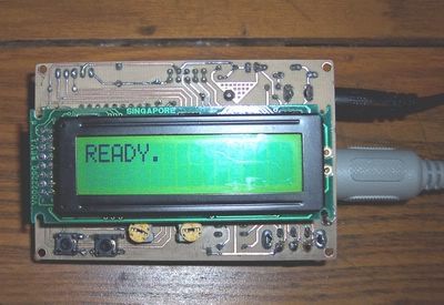
Yeah, the MIDIMon is actually the main thing I made that for, but not for the LCD data monitor. I want to mess with some of Thorsten's seven segment code and matrix displays, and learn about the shift register handling for it. :)
I'll likely be using it with no LCD for that stuff, but will have one around for the inevitable "emergencies". :-[
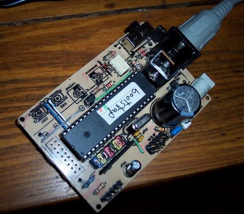
It's got a few pin headers on the bottom for the d.in/out and a.in mux lines, and a jumper block to hold the Bank A lines @5v, or take them to external pots or whatever. The LCD socket is just a cheap 16pin DIP socket, cut in half. I bottom-soldered it with the pins set a bit high, so I could get to the joints (still a PITA), then hot melt glued around it so it couldn't move. Afterward, of course, I realize that my backlight pins don't go +/- for 15&16, so I have to cut into the glue, shave out a couple traces, and jump them back in reverse. Is that a common occurrence with the last two pins on some LCD's (may be worth a note on the LCD wiring PDF)?
One of those high quality "long-legged" DIP sockets would be best for the trace side wiring, but I only had 14's here. >:( I'm thinking of moving to one of those nice looking PCB mount female header sockets for the LCD (the ones that look like the end plug of an IDE ribbon), and moving to a double-sided board, mainly just for those LCD traces. The PIC pinning, and the LCD location I used, puts a bunch of them in a really inconvenient order, so I just ran most of the traces for varying lengths away from the LCD socket, horizontally, and terminated them with pad holes, which jump down to the correct PIC pins with short wires on the top. It takes a few jumpers, but they're in neat parallel rows and they're ultimately hidden by the PIC (as are a couple caps and resistors, IIRC. The double-sided LCD traces and female header would make that a lot easier, but I figured if it worked, and I could refine it a bit, someone else here might like to make one for something, and I don't know what most of you guys are doing for etching, or how much trouble D.S. boards would be. With D.S. traces there, you could land them directly over the area just inside the PIC socket legs and solder a short wire from top to bottom, almost as easily as laying a jumper.
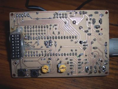
Here's the bottom view:
There's a DPDT slide switch and a pin2 ground jumper at the back, which will turn the MIDI jack from an input to an output, for unidirectional MIOS devices, once the PIC's contents are finalized. Output mode is actually a bi-directional dual pinning, where the outer two DIN socket pins carry the input lines (used with an adapter), or you can just run a standard MIDI cord for output only. I'm about to do a 5pin to 15pin male, for a direct gameport cable, and may also look into an LTC based "direct-to-COM" addition.
Still wondering about the 9V battery if anybody knows? There's a pin header for a 5v output, but it's post-regulator/filters, so maybe a couple holes somewhere else, for external battery wires would work.
Funny, I'd like to get it into something, so I can throw it in my bag, but don't want it that much bigger. I thought about slicing a small chunk of 2x4 in half, and drilling out the insides for a small case like you mentioned. I'd also like it to be able to stay in there while I use it, so I guess I'll need holes for the sockets. With the case in mind, it may also help to move the four mounting holes out a bit, with some empty border area, so it could screw down flat on something. Otherwise, I can always stick a couple scraps of foam on it, or wrap it in cloth, and secure it with a rubberband.does it fit in a boxSad part is, I now have a whole batch of portable MB devices I made, so I can carry them around and play with MIOS/app assembler code, and so far, I don't appear to be carrying around anything. 8)
I was also thinking of doing modular "stacked" boards, with a header block at one end, and maybe a couple spacers on the other, along with a matching female socket on the bottom. That way, you could squash together a whole "brick" of core/d.in/d.out/a.in's, or whatever, maybe with those five pin 90 degree headers on their edges for any external part connections. I guess a socketed PIC, or the heatsink/caps, might get in the way there, unless you used a taller "link" socket or pin header on the core, or a regular external LCD/cable with the PIC on top, or you could take the main core link to the first board with a short ribbon and 90 degree dual row headers on the edge. ???
BTW-- Anyone think the heat of a small box-enclosed core is worth considering? I thought about putting some extra room on the sides of the regulator, maybe for the option of using those "fancy-finned", "bat" looking heat sinks.
Also, I might add a few easier direct connections, for a small number of optional buttons (or maybe even LED's). Right now, it just has the usual (2) MIDIMon buttons, which pull the first couple Bank A lines to ground, and I left out the ICSP stuff (I'll probably want that).
Can those two (or more) buttons on Bank A be easily configured to control the same MIOS functions of a regular "D.In" input, by shorting to ground on closure like that? It would help if I could work on button code without extra traces, boards, or shift registers, but I don't want to work with code which will require a bunch of repatching to use in a regular box.
Thanks!
George
PS- @BpM- Sorry for the thread hijack, but I guess they've already shot down the inverted LCD idea. ;)
-
I'd make mine out of half-inch plywood with the intent of it being permanent.
I was thinking the other day, after looking at this, there's also usually an aluminum "L" channel stuff at those home centers (at least here in the US). It's usually in a vertical bin of long metal crap, in the metal section, like metal dowel rods, threaded rods and flat bar stock. It's cheap (IIRC), and could easily be chopped into little segments with a hacksaw.
With that, you could probably use really thin stuff for the weight (1/4" ply, or even sheet metal), and maybe even rivet through the sheet mat., with the "L" stuff on the inside, then you'd avoid all the screwing, gluing, or joinery. Should be plenty strong and quick, and should take care of anything with 90 degree corners.
This is all assuming no one's going to see the back "enclosure" section, like NorthernLightX's sounds, but I guess that depends on the look you're going for, or the type/finish of the sheet stuff. If you can manage to cut beveled edges in the sheet, you could maybe even conceal the joints. The "L" channel on the outside might look cool too (sort of rack case'ish), but I'm not sure if the rivets would squish through the ply on the inside. Maybe washers would help. FWIW, I've gotten nice durable, textured-finish beige and black sheet stuff out of the side/top panels of old computer cases and the covers of broken stereo equipment and VCR's. It's hard as !*$x# !#$% to cut, and leaves a nice dangerous edge if you can't file it or something, but big metal shears might handle it, or the "L" on the outside could cover it. As you know, it's usually in a "U" shape, so if you picked the right piece, you may even manage to get three pre-bent sides with no joinery out of it.
Hope that might help somebody,
George
PS- NorthernLightX,
Your box thing's given me some ideas for later (maybe much later -too many plans here). Years ago, I bought actual textured plastic from a local dealer, when I used to have to carry gear around, and have been saving it, along with some aluminum "L" I had bent by a siding contractor friend, into that weird shape you see on road case edges. The plastic's pretty cool (got black & gray). It looks, or is exactly like the Anvil stuff, and is flexible (unlike regular laminate). Still don't know why they carried it, but it probably wasn't for road cases. I think I've seen it in high traffic areas like elevator walls or somewhere.
-Thanks!
BTW--> I've managed to lose a piece of the aluminum tongue and groove cover joint stuff they use (the groove half actually). I'm going to head for the rec.audio "live sound" group, or whatever it's called soon, to try and find one. It was only about six or seven inches longer than rack width (cut it for a 3-space), and it's the one for the thinest ply (maybe the 1/4"). My dealer here closed a few years ago, so I'm really just looking for a leftover piece from someone who uses it.
-
BpM,
Figured you might like to see this core thing I've been messing with
the past few days, but was on the way out earlier and didn't have a
picture.-
I've gotten into smushing things lately. ;D
I've hit similar deals as you, with the LCD connection, but with me, it was that the header layout didn't match either of the two types I've got (16pin 2x16's and 14pin 2x40's with 2 BL leads). I also wanted something I could carry around with no outside jacks or wires, other than the MIDI and power, so I moved the LCD header to the end of the PIC (after arranging the pins), and used a female socket, so I can press it directly onto the core. It's got holes to screw it on, but I'll do that later.
Coincidentally, when I was laying it out, I was forgetting that the LCD was going underneath it, so I ended up with the jack on the right and an upside-down deal, like you were asking about (but not a usable one). I ended up having to re-route all the LCD paths to go the right way, and move those two buttons. >:(
I guess at least I hadn't etched yet. :)
Here's one with the display pulled off.-
I think that's about as "smushed" as it's going to get here, unless I can get a surface mount PIC. Seems like it all works alright, but I made my usual one or two stupid, careless mistakes, so I may change a few things and re-do it.
Take Care
George
PS- How fast would anyone here guess an 18F PIC/LCD would eat up a 9V battery?
-
Erm.. that's my stated goal. Profit is not involved, however.
Apologies, I probably wasn't clear enough on that. I just meant that if you get deep enough into the whole MIOS structure and what the apps and functions are doing (as well as the circuitry obviously), you may find it easy to build unique devices that you, or others may need, either as enhancements or additions to the MB code (for others here as well), or even separate devices for use with digital music gear, or any digital hardware for that matter.
Some of what I've learned here has enabled me to work with basic serial MIDI i/o from smaller PIC chips, and I already have several ideas for that stuff, for my own personal needs. It's also given me a much better understanding of serial i/o and "bit banging" junk in general, which I may use for anything (I'm currently playing with some PIC IR transmission).
Hang out, learn, have fun, and stop arguing. (please)
George
PS- I still like the idea of MB's for "trade". I can't see anyone here having a problem with that (can I?). If you were constantly making new boxes (not duplicates), but couldn't realistically use them all, wouldn't trading them for other music gear that you needed (not $) be an agreeable solution? It seems if you had something cool, and threw a WTT message up say, in a for sale forum or newsgroup, with a link to some pictures, and stated "I'm looking for this, that, and this, but I'll take offers", if it was a cool enough box, it seems someone would have something nice sitting around that you could really use.
???
-
I guess you're not talking about reversing the actual "pin order" ;) (too many non-data pins would show up in weird places)
If you mean writing "upside-down" to the display, I think the character LCD's recognize a set group of codes for the characters, so I'm not sure even a massive software hack would be able to send them upside-down.
(someone please correct that if it's wrong)
Take Care
George
-
You simply don't get IT?
"the license" or the way You see it doesn't matter.
That's my take on it as well. If you've stopped for more than 10 seconds to even think about the legalities of stuff like this, then you're probably already screwing up. :-X
Saying "changes to MIOS" already points out, that you don't know how MIOS is working.8) To play devil's advocate here:
Robert, I can't speak for Thorsten, but from the impression I get of him, and the people in here, I doubt most of them would want to lock you out for that proposal, or even that they wouldn't be thrilled to see you learning more about what some of this stuff is doing, so that if you're still interested, you might even start producing new devices down the road, for profit or otherwise, and hopefully be able to help some others here with what you'd learned. I'm guessing maybe it's more a matter of just not hanging around here long enough to really see how most of the people feed off of the ideas and knowledge that's floating around. You may find yourself more interested in that, than the construction or even sale of boxes. That's my main reason in here, and I'm happy to say that I've learned way more about digital electronics and basic assembler code, by having something practical and creative to apply it to, than I ever would have otherwise.
Take Care,
George
-
Looks like you and me are running the same firmware or something. ;)
http://www.midibox.org/forum/index.php?topic=5188.msg32025#msg32025
I'm really into the single-control idea as well. Not only for plugs and processors, but for basic functions like volume/pan/solo/mute. If it were easy enough to bounce from one to the next, the controls or lights were being updated accordingly, and you had some visual feedback as to where you were, you almost wouldn't need all the channels.
We've only got two hands anyway (well at least I personally do). ;D
Take Care
George
-
FWIW- You can also get rolls these days of actual veneer at home centers (or better places), which could easily cover a plywood MB-sized enclosure. That way you could use whatever substrate was easiest to edge join (even heavy particle board), or cheapest, and still get a nice natural grain. It can also conceal the edge joints, so you could go with something simple like 90 degree butt joints. If you ever try it, make sure you're using made-made composite stuff for the substrate, like ply/p.board, because if it moves at all with the climate or moisture, it could possibly pull away from, or break the veneer.
Stuff I've gotten at home centers here is pretty thin (maybe under 1/16"). It was in a 2' wide roll, but I don't remember the exact length in feet. Here in the US, they usually have Maple, Birch, Walnut, and Oak, but actual woodworking suppliers would have the more exotic stuff (maybe pricey).
It goes on with wood glue, but I think I've even used regular contact cement for plastic laminates (that saves you the clamp and time hassle).
Sorry, got a tiny pinch of "cabinetmaker" in me. ;)
Take Care (and nice box Alex)
Wish to make an Ableton Live foot controller... have some questions
in Design Concepts
Posted
Keyz,
Sounds almost exactly like what Guatamaham was just asking about. ( - take the elevator up one post and turn to your right)
If your looped events continue to play after the triggering, the "clip to MIDI" feature he found should keep the MB lights on at the correct times for you.
The module config. you describe should be more than enough (up to 32 buttons/lights per D.In/D.Out board). Someone in the know may even be able to edit the app, to get some of what you need directly from core, bypassing the shift register stuff, since there may be a bunch of unused bank pins.
If you're not an X-Man mutant or anything, I'm not sure how easily you could see that status display from a standing position. I think dakro69 on eBay had some extra large 2x16's, but I don't know how large, or whether they were even lighted.
Take Care,
George
PS--- Man, we need that 7-Segment output. ;D
I'll try to get my thing together and carry it to the studio tonight to start on some digit attempts, but mine may not be for the same parameters.