seppoman
-
Posts
1,065 -
Joined
-
Last visited
Content Type
Profiles
Forums
Blogs
Gallery
Everything posted by seppoman
-
MBHP_ETH, MBHP_SDCARD, SSM2044, SSM2164 PCB Bulk Order
seppoman replied to seppoman's topic in Bulk Orders
well not entirely by hand (although that wouldn't take that much longer). I'm using a reflow oven, then remove any excess solder by hand and finally use an ultrasonic bath to remove any flux remains. There are 65 pieces ordered and I'm estimating two evenings of soldering, so it's not that bad ;) S -
MBHP_ETH, MBHP_SDCARD, SSM2044, SSM2164 PCB Bulk Order
seppoman replied to seppoman's topic in Bulk Orders
your link is a complete module which could probaby be used as a replacement for the ETH module if you know how to connect it. There are several similar modules on offer, but using one of these wouldn't be very DIY ;) I would be very surprised if there's really no shop in Australia carrying the ENC, it is available virtually everywhere in Europe and the US. And it's a cheap item and you need only one per module, so shipping cost will probably kill any discounts in a bulk order. If you're not too much in a hurry and are planning to order at Digikey or Mouser in the next months, better get the ENC there, together with the MagJack - which is much harder to find than the ENC even in the US. S -
MBHP_ETH, MBHP_SDCARD, SSM2044, SSM2164 PCB Bulk Order
seppoman replied to seppoman's topic in Bulk Orders
The PCBs are ordered but not yet here. As soon as they arrive, I will need another few days to solder all these card sockets ;). In the next days I will start writing all docu and parts lists etc. so people can already acquire the necessary parts. As soon as something's happening, I'll post updates to this thread. S -
well maybe seppoman has ;) The easiest solution is to use two (linear) stereo pots together with some resistors. Cutoff is about 5 V for closed and -5V for open filter. Resonance is 0V for no resonance and about 10.7V for full oscillation. you can use some resistors to build voltage dividers between the supply rails that operate in the required range. With this basic solution, you might need to experiment with these values to get good results. The proper solution would be to use some TL074 opamp in a voltage follower configuration to buffer these voltages independently so there's no interaction between the two filters. The opamp output is also a low impedance source, so it's guaranteed that there's no influence of the pot value/setting on the operation of the filter. S
-
Thanks for reminding me that this stuff exists. I've seen a video some years ago but never bought that stuff. As there's obviously no way of buying ChipQuik in Europe, I've searched the net and read on the mikrocontroller.net wiki that ChipQuik is probably similar to the so-called Roses Metal. This stuff can be bought (in large bars) from TMP-Loettechnik in Germany - there you can get a 100g piece for a similar price like the ChipQuik starter set. I have ordered this stuff and will post my results after trying it out :) S BTW I'm moving this thread over to Tips & Tricks as it is also relevant for GM5 etc. and maybe won't get lost on the tenth page of the forum so quickly.
-
SIDSynth testing,watch the video and tell me
seppoman replied to GordTheRogue's topic in Testing/Troubleshooting
That looks very much like a wiring error. When there's loose wires or wires are swapped etc., almost everything can happen on the LCD as it'll receive only crap. Check all wiring again and make sure all wires are in the right place. If you don't see any error, maybe try out the lcd interconnection test app (from MIOS8 download page). Good luck S -
und wenn Du im englischen Teil posten willst, machs bitte unter "Miscellaneous". Auch wenn das Thema nur so halb "off topic" ist, nachdem wir immerhin auch über den SID eine gewisse Verbindung zum C64 haben, kann sich hier bei uns eigentlich nur zufällig jemand rumtreiben, der Dir helfen könnte. Bessere Chancen auf konkrete Hilfe hättest Du sicher in einem echten C64-Modder-Forum, da gibts auch ein paar im Netz. S
-
Problems about Traktorizer , a new build .
seppoman replied to DarKM4N's topic in Testing/Troubleshooting
an empty screen after (only) MIOS is loaded is perfectly normal in your case. As long as you don't compile a custom MIOS version or the application selects another display type, MIOS will only try to output data for a HD44780 standard character LCD. The Nokia display can't make sense of that. for all other questions someone else has to jump in as I haven't got any personal experience with Traktorizer or this display type. S -
As you have a scope, you could check if there's still a signal after the optocoupler, i.e. measure at the PIC UART in pin. But 90% of all upload problems are caused by incompatible (bad) MIDI interfaces - so which one are you using, which OS etc? The XP compatibility mode of Windows 7 has also been reported to cause problems - or using 32 bit drivers in Win7/64 etc. S
-
well as long as it's only one single trace that is damaged, you can always fix it with a piece of isolated wire. Just solder one end of the wire to the pin/pad where the damage occured, follow the trace to the next place where it goes into another pad, and solder the other end of the wire there. Another way of fixing ripped off pads is to scratch off the (red) solder mask laquer from the trace end for maybe 5-10 mm, apply solder to the copper of the trace, bend a short piece of wire or a leftover resistor leg that crosses the gap, and solder this piece between the pad and the trace. Buying a new PCB and starting all over is a bit of an overkill as long as you didn't kill half of the traces :) good luck, S
-
MBHP_ETH, MBHP_SDCARD, SSM2044, SSM2164 PCB Bulk Order
seppoman replied to seppoman's topic in Bulk Orders
I've sent Paypal invoices to all participants of the bulk order. If you didn't get an invoice or there's any mistake in pcb numbers etc, please contact me as soon as possible. Expected time frame - as said above I'm planning to order the PCBs in a week, then it will take about two weeks for manufacturing/shipping to me, so you can expect to receive your shipment in around 4-6 weeks from now. S -
MBHP_ETH, MBHP_SDCARD, SSM2044, SSM2164 PCB Bulk Order
seppoman replied to seppoman's topic in Bulk Orders
just a short reminder that today is the last day of the regular bulk order period. I'll start sending out Paypal invoices on Monday and am planning to order the PCBs about a week later, so I'd be happy if you could pay reasonably soon. As long as the PCB order isn't placed yet, I will still accept orders from late-comers and I'll order some spares, too. So don't panic if you're a few days late. :) Still, after experiences from previous bulk orders, I have to point out that I won't wait for payments forever and will send a reminder one week after the invoice :poke: and consider the deal cancelled after three weeks if you don't contact me and come up with a good excuse :whistle: S -
so finally I managed to do a little demo using both the ssm2044 filter and the 2164 vca (with mbsid and 6581 sids). 0.00 - a sound with very high resonance, cutoff is modulated by key velocity. The filter is at the beginning of self oscillation. 0.15 - same sequence but using the vca to mute the oscillation during pauses. 0.28 - another high resonance sound with cutoff frequency tracking the played pitch, i.e. using the filter as a sine oscillator. 0.35 - same sequence using the vca. 0.46 - again a high resonance sound with cutoff as a high octave. 0.54 - same sequence using the vca, playing around with gate length and vca offset ("influence"). I guess everyone can imagine how key velocity controlling note volume sounds so I didn't record an example. Please disregard the zipper noise present in the second and third example - I did some experiments with capacitor values last week and only remembered that after having recorded the demo and listening to the mp3 with headphones... Problem here is that the AOUT update rate on MBSID is quite low (every 2 ms), so very fast envelopes make the "ramp" of a fast attack consist of only one or a few value changes, i.e. there's huge jumps in the CV signal and the 2164 reacts with some noise. This is compensated by low pass filtering the CV a bit, in this example it's obviously not enough filtering. There's only a fine line between having these noises and filtering too much, i.e. killing the snappiness/punch of the VCA, but I'll specify a good compromise value in the final parts list. S 2164demo.mp3
-
Hi and welcome :) adding a parallel 10k resistor doesn't change anything - in mid position, the wiper still has 235k resistance in reference to VCC and GND. The 10k faders is a reasonable recommendation, but that doesn't mean that 5k or 20k don't work. But 470k is quite a huge value, you can try them but you'll probably get very unstable/jittering values in the middle area of the faders. So probably you will need to buy some new 10k faders. Seppoman Nochmal kurz auf Deutsch: ausprobieren ;)
-
MBHP_ETH, MBHP_SDCARD, SSM2044, SSM2164 PCB Bulk Order
seppoman replied to seppoman's topic in Bulk Orders
PM is "Personal Message", you can send me one for example by clicking the little envelope symbol on the left side of this forum post :) -
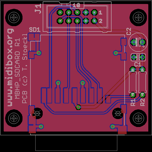
The SD PCB is 45x40 mm like stated in the original bulk order post :tongue: I'll have to catch up on documentation soon and post more details/Eagle files. S
-
MBHP_ETH, MBHP_SDCARD, SSM2044, SSM2164 PCB Bulk Order
seppoman replied to seppoman's topic in Bulk Orders
I didn't promise to send any instant confirmations - you can take the Paypal invoice that you'll be getting after the order period has ended as a confirmation. :) S -
yes that's right, so far there's no documentation for this board. It was a spontaneous decision to offer pcbs for this module, too, when I set up that multi-bulk order, so I didn't prepare any docs/parts list etc yet. I'll change that in the next 1-2 weeks. again, quoting myself :) Just like the SSM2044 module, this one wasn't designed with a modular system in mind. It's meant to be used together with a (linear) DAC/AOUT, doesn't have multiple inputs/outputs per channel, no connectors for pots (e.g. for adjustable overall volume or depth control). Instead, it's designed to be a small, cheap, easy to build addition to Midibox/AOUT projects like MBSID or MBFM (maybe you could also use these pcbs to build a simple "vca automation" box in conjunction with a MB64 core, as this thing has a really good s/n ratio etc). I'm not saying it's not possible to use it in a modular synth, but there are other SSM2164 based VCA modules out there that are designed for that usage and save you the hassle of adding external stuff to expand it to full versatility. - That being said, 15 V should be fine :ahappy: S
-
please allow me to quote myself :tongue: It seems that last promise was a lie :whistle:, but I'll do some audio demos next week. Personally I think that VCAs are quite useful for a MBSID. But of course, as a good VCA does only change volume but not alter the sound, the benefit is less spectacular and obvious than when adding nice VCFs. So if you can't imagine what to do with VCAs and maybe you're not too much into synth/sound programming anyway, you probably wouldn't need these extra VCAs. But if you already have good VCFs and you think it's fun to expand your MBSID even more, and you like to program/alter sounds and explore the possibilities, adding this module is definitely a good thing :thumbsup:. S
-
MBHP_ETH, MBHP_SDCARD, SSM2044, SSM2164 PCB Bulk Order
seppoman replied to seppoman's topic in Bulk Orders
that parts list is correct, except that the pcb contains 3 (not 1) 100nF capacitors and doesn't list the two 220 Ohm resistors needed for the MagJack LEDs. S /Edit (TK): fixed -
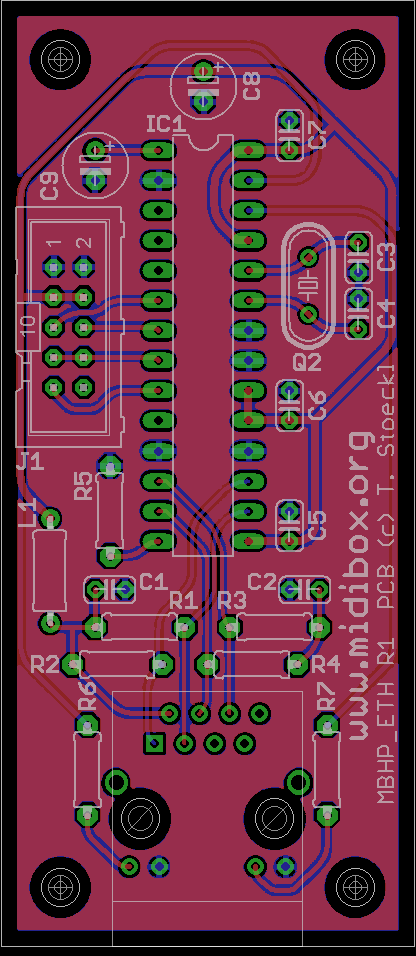
[update] I've got a few spares of the ETH and SDCARD module available, and there's about 50 spares each of both SSM PCBs. The ETH/SDCARD spare PCBs are meant to bridge the gap until SmashTV will eventually start offering these, so please only order these if you know you won't just put them on the shelf for years but you will use them in the next months. I won't sell more than one of each per person if you don't come up with a good explanation why you would need 10 ETHs immediately ;) If you want to order some of these PCBs, please follow the instructions below. S [original post] Hi *, lately I've been working on the layouts of two new official MBHP modules, the ETH (ethernet) and the SDCARD (SD reader) and I'm now offering them in a bulk order :twitch:. Both have the standard ribbon connector so that you can attach them with a 1:1 two or three connector ribbon cable (like TK showed in this pic of his protos). For now, these modules are mainly useful for a MBSEQ V4 or for programmers (your own projects). Support will increase as TK makes progress in porting stuff to the new MIOS32 platform. The ETH uses the classic MagJack connector that is widely avalilable. PCB dimensions are 80x35mm. The SDCARD is 45x40mm in size and includes the matching Multicomp SD socket already presoldered. This socket is a very nice "push-in/push-out" type. As a lot of people were asking for a second run of my Dual SSM2044 VCF PCBs and I'm facing the usual bulk order madness anyway :drool:, I thought it'd be nice to offer these, too, and even my new . Please note that this time, there's no extra bulk order for the SSM ICs, but you can get the 2044 from several eBay dealers and the 2164 is still in production by AD, so you can buy them new at various places like Digikey, Farnell etc. It probably makes sense to combine orders with fellow bulk orderers to save both on shipping and IC cost. As this bulk order is about 4 different PCBs, please keep this thread clean from "why would I need these, can I do thisandthat with it?" posts, instead post this type of questions e.g. to a new thread in the Design Concepts forum. now the terms and conditions: All PCBs are 5 EUR each, except the SDCARD including the presoldered socket is 7 EUR. Deadline for ordering is April 11th. This time I won't setup a wiki page to collect orders, instead please fill out the form below and send it to me via PM. I'm accepting payments via PayPal or EU bank transfer. When paying via PayPal, the usual PayPal fees will be included into the "shipping" price. If you want to pay via bank transfer, tell me and I'll send you my account details. Shipping will be done with Deutsche Post. Registered mail ("Einschreiben") is optional (+ 2.05 EUR) and includes basic insurance, but please note that I won't be responsible for lost shipments if you decide against this option. Shipping rates (including 20 cents for a padded envelope): 1-2 PCBs: Germany - 1.10 EUR Europe - 1.45 EUR World - 2.40 EUR more PCBs: Germany - 1.65 EUR Europe - 3.60 EUR World - 6.20 EUR ---- Order Form ----- Real Name: Postal Adress: Country: Number of MBHP_ETH PCBs: Number of MBHP_SDCARD PCBs: Number of SSM2044 VCF PCBs: Number of SSM2164 VCA PCBs: eMail adress: PayPal eMail adress: Shipping insurance (+2.05 EUR): [ ] yes [ ] no ------------------ Happy DIYing :rolleyes: Seppoman
-
yes that's the 16b - are you in Germany? If yes, there's also Buerklin who stock them (but only sell to commercial customers as long as you can't visit them in person in their Munich store). I don't know about the 12b - you can try to compare mechanical drawings and pin configuration in the pdf datasheets of the two models.
-
The kit encoders are a (quite good) chinese clone of the Alps STEC16B series. Don't know if Conrad stocks these.
-
It could be some bad contact on the CS PCB, maybe around the resistor networks. But most likely the encoder itself is faulty. Maybe it got too much heat or a strong physical hit. If you don't find any other issues on the PCB I'd suggest exchanging the encoder for a new one. Edit - "every 16 clicks" - maybe the encoder is a version with 16 clicks per rotation? That's a usual number of clicks. So maybe you can try out if it always happens on the same position of the encoder? If that's the case, it's definitely a faulty encoder.
-
Don't know if Commodore used different PSUs over the years, but the Amiga PSU I have is definitely a linear PSU. S