seppoman
-
Posts
1,065 -
Joined
-
Last visited
Content Type
Profiles
Forums
Blogs
Gallery
Everything posted by seppoman
-
Stacky, it's really enough now! Rephrasing "I need a circuit diagram 4 this" doesn't make the question any better. This whole thread doesn't talk about any PCB at all. http://www.ucapps.de/midio128.html is the link to MIDIO128, that's the project these guys were talking about 6 years ago... Generally, 99% of all the posts in this forum are about projects you can find (including cirquit diagrams and PCB layouts) on ucapps.de. So your questions don't make any sense as they're put in a very general way. After you've read the stuff on ucapps.de, when more precise questions occur, this forum will be a very helpful community for everyone, but as long as you don't even tell people enough of what you want to do and what your problems are, these posts really REALLY don't make any sense. I guess English is not your native language, so if you've got problems phrasing your questions in English, consider doing that in one of the "Multilingual" subforums. just please STOP posting these half sentence nonsense questions or I'll start deleting these posts in the future! S
-
What do you guys think of this MIDI interface?
seppoman replied to bodimix's topic in Design Concepts
oh come on, please stop asking for circuit diagrams in every thread ;) Regarding Midibox stuff, please read the ucapps.de website and the Wiki before asking for diagrams again. Regarding this actual "Audiopad" thing, please read the website http://www.jamespatten.com/audiopad/ that was already linked in the first post. If there's more questions about it, why don't you ask the guy who built the thing? Nobody on this forum is in any way related to this project so it makes no sense to ask here. S -
There is no such thing as a "10k encoder" ;) just use one of the regular/recommended types from Smash, Voti, Alps etc. Faders should be 10k linear. S
-
you can't really test a trimpot as long as it's soldered in place. But as the trimpots are not directly connected to either +12 or -12V at any point, a damaged trimpot can't be the reason for your short. Just check everything again, with a magnifying glass if you have one. The only places where the supply rails are somewhat close to each other are between R44<->R36 and R45<->R37 and maybe around J3,J4 or C1,C2. Or the short is not on the pcb but on the PSU/wiring. If you still don't find a reason for this short, maybe post some high resolution pictures of both sides of the pcb, including wiring. Maybe someone else can spot a suspicious solder joint. S
-
Yes, and a multichannel 24 bit audio interface, WAN access and maybe an integrated DVD burner... sounds like you really wanna have a PC :P
-
WIKI perhaps a prob, my workaround.
seppoman replied to RoyalScam's topic in MIDIbox Documentation Project
Yes at least that works ;) s -
WIKI perhaps a prob, my workaround.
seppoman replied to RoyalScam's topic in MIDIbox Documentation Project
Uhm, strange - I know it did always work in FF, but I just checked it and my FF 3.0.9 also does this fetch.php thing and doesn't show the file. so either the problem came in one of the newer FF versions or from an updated Wiki soft? (I didn't install any new FF extensions or special Acrobat version etc) S -
"last week" - "a few days"? I guess it's a bit early to be worried?
-
DOUT max. current supply / driving LED's / BLM
seppoman replied to This N°9's topic in Testing/Troubleshooting
well ok, I didn't try this shake head thing lately, either I mixed something up or MIOS behaviour has changed at some time. btw duty cycle doesn't necessarily mean multiplexing, you could turn on the outputs for 2 ms and off for 2 ms and you've got a duty cycle ;) Anyway, I guess this proves that the 595s can take some more current than the datasheet says. Still I'd suggest not to drive them much further over the limit or else a failure would become more probable. S -
DOUT max. current supply / driving LED's / BLM
seppoman replied to This N°9's topic in Testing/Troubleshooting
I guess ON will know better than Distrelec what their chips can take ;) It's great that you did some tests with positive results, but if you wanna build something that's supposed to work without failure in all environmental situations and for several years, you should better accept what the datasheets of the manufacturers state and stay at least below 100mA. the word is "duty cycle" - did you ever shake your head quickly while looking at a MB? the LEDs are only on part of the time so the average current is lower than calculated. If you're interested in numbers, you should ask TK. S -
you'll need a DIN module as well, only 8 inputs can be used directly on the core module. The audio in is located on the SID module, no need for an AIN. S
-
you can't damage anything by leaving out the cap. But the 78xx datasheet suggests using caps, so in some very unlikely event the supply might become unstable without it. Better replace it with e.g. a 100nF cap than leave it out. NO!!! the cap is between the supply rails so shorting it would make your PSU smell funny :o S
-
oh please not THAT discussion again - from my own experience I can assure you that buying ssms from HKSS/Goodbuy was a smooth transaction and the chips were not fakes ;) Aside from that, Doug is recovering from a serious illness and has visited the chat several times recently. He's got a huge pile of group buys etc. to catch up on (panels etc), so if you've ordered SSMs from him, just be patient for another few weeks, I guess he'll contact you soon. S
-
Try the words "cathode" and "anode" ;) S
-
ich dachte du wolltest dich nicht mehr über Bier unterhalten :P S
-
Midibox64 Encoder and Traktorizer question
seppoman replied to FJMSoft's topic in Testing/Troubleshooting
since v2.1 you can also use pots with MB64e - quote from http://ucapps.de/midibox64e_changelog.html: S -
well you don't need to move envelopes around on the CAN bus to use the other two VCAs for another SID pair - just go old-skool and simly use wires ;) nobody stops us from connecting the other two audio and CV connections to another SID/AOUT :) so in fact doing VCA feedback doubles the number of modules needed for a full mb6582 from two to four. yes that diagram is what I'm doing. What do you mean with "bypass all oscillators"? I can only switch them on or off, and with off the only thing left would be a sine as long as the ssm filter is set to oscillate. uhm why would I want to not use the SID filter at all and still need the feedback loop? I thought the whole intent of doing feedback at all was to increase the VCF's resonance, no? about DC/AC coupling - yes I'm using the J3/23 connectors for feedback. I already noticed there might be an issue with this... the SID probably works on a virtual GND scheme and the Sid module (and the mb6582 pcb as well) use an electrolytic cap on the output to AC couple this. So the output is probably going about 0V, but the mb6582's audio input AGAIN does AC coupling which is probably not necessary in the feedback situation. with or without this second cap, the ext in of the SID is getting an AC coupled signal which has a huge negative DC offset compared to what the sid's output is giving. So I guess to get good effect of the feedback it would make sense to not use the intended connector but grab the output signal from before that cap and feed it back after the input cap? Guess I'll try out if that helps to improve performance :) S
-
OK I've checked out using the VCA for controlling the SID feedback a bit more in depth - originally I hadn't thought of activating the external input flag ;) so it IS possible to do this (doesn't hurt to adjust the VCAs for a little more gain), but I still find the effect not really exciting. Feedback seems to be an easy way to give the SID's internal filter some more resonance as long as you don't have external VCFs, but the change isn't drastic enough to justify doubling the number of VCA modules and using up the last two remaining CV channels on my AOUT_NGs. If I want mean resonance, I'll continue using my ssm2044 vcfs for that :D S
-
well with MBSID V2 you can't move around AOUT channels over the CAN bus anyway so you'll need to use one AOUT module per core :) I used the feedback pot connector of the mb6582 board, i.e. put the VCA between audio out and audio in of the SID. No additional parts. do you think a coupling cap would make sense here? S
-
The frequency modulation would instanly destroy all ICs :P No sure, why not? :) yes, I got it directly from AD as a sample some years ago ;) the 2044 module is 90x60 mm, so no they don't line up - do you think it would be cool to make the PCB the same size? I didn't want to waste space and you'll need two VCF modules to feed all 4 channels anyway, so you'd probably place it between the two anyway. Well e.g. for a regular mb6582 configuration, you'd connect the audio out of one sid pair to the audio in of the VCF module, connect the audio out of the VCF module to one audio in pair of the VCA module and the output to your output jack. CV connections: first four CV outs of an NG go to the VCF module and two others go to two channels of the VCA module. Second half of the VCA module would be free for another core/sid/aout/vcf pair. I'm still researching if it makes sense to use the two other VCAs to control the SID feedback level. I've tried that out once but got mostly a little variation in level, not very exciting - either I made some mistake or the 6581 simply doesn't give much effect by using feedback - I'll have to try it with 6582s :) hehe, does it already smell that strongly? ;) Well I could imagine something like that happening soon :D S
-
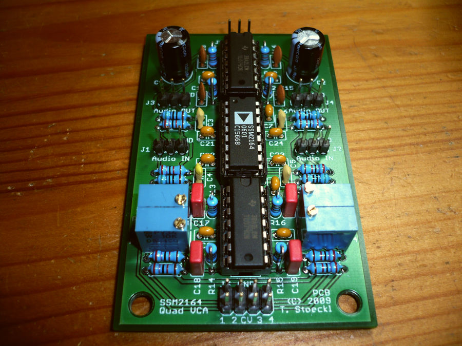
Hi, I've just finished the first proto of my new module - a quad VCA based on the SSM2164 IC 8). The 2164 incorporates four high quality VCA channels with logarithmic response and is one of the few highly integrated synth-related ICs which is still in full production (by Analog Devices). The logarithmic response is kind of unusual for a synth VCA and not very suitable for modular synths (because most envelope generators already output exponential CVs - some reading: http://www.synthmuseum.com/magazine/linexpo.html). But for use as a (final) VCA e.g. of a Midibox SID, the log response is perfect - the CV generated by routing an envelope without tweaking the curve parameters to an AOUT channel is linear so the ssm2164 will give the same change in dB for the same relative value change over the full range. While not as obviously exciting as a VCF, a VCA is a very useful addition - e.g. it serves as a noise gate for 6581 lovers like me, adds the possibility for true velocity sensitivity. Another great effect in conjunction with a VCF like my SSM2044 module: if you set the VCF to full oscillation with max keytracking, you can use it as a fourth (sine wave) oscillator. Sound demos to follow in the next days :) The module is 50x80 mm in size, parts cost is about 10-15 Euros (for four channels! :D) S
-
Also als anständiger Bayer/Münchner, den's nach Düsseldorf verschlagen hat, muß ich hier mal dazwischengehen und sagen ich mag beides, Country UND Western ;) Und im Sommer kann man auch statt nem Wasser zur Erfrischung gut ein Kölsch trinken, selbst als "Düsseldorfer" :D Immer noch besser als das miese Becks was hier alle cool finden zu trinken - so, jetzt muß ICH mich wahrscheinlich warm anziehen ;) Ich fahr jetzt erst mal zu meinem Lieblingsgetränkemarkt und kauf mir einen schönen Kasten Augustiner :D S
-
http://www.edrum.info/
-
schon wieder daneben :P PIC18*F*452 :)
-
Haha :D glad I could help :)