

Altitude
-
Posts
1,184 -
Joined
-
Last visited
-
Days Won
30
Content Type
Profiles
Forums
Blogs
Gallery
Posts posted by Altitude
-
-
I have a pair. Pretty sure I have the VCA ones also
-
> Is your shift button pulsing each quarter note when the sequence is running/ illuminated when held down to change modes etc.? I'm using an F1 Core, so it could be related to that
Nope, not pulsing.
> Did you configure the routing from the MIDI menu? You have 16 nodes to play with. What do you want to send where?
I figured out what I was doing wrong, on the Jam page, you need to set the channel for the forwarder to work.
I guess the next question is can those routing be fixed so midi input 1 can be routed to G1T1 (or whatever)
-
Hm. Are you talking about the column above the shift button ? Seem to work fine here
Unrelated:
I am working on getting more inputs (namely a keyboard and drum pads) set up and I can seem to figure out how to get them to work correctly. The BLM keyboard mode works fine and the monitor shows activity on the input channels and I have the forwarders turned on for each track. I am sure I am missing something obvious, can anyone shed some light?
-
We will see how it goes. 25 ppl is the critical mass for this. If we dont get there, I'll just release the files and people can get them made where ever
-
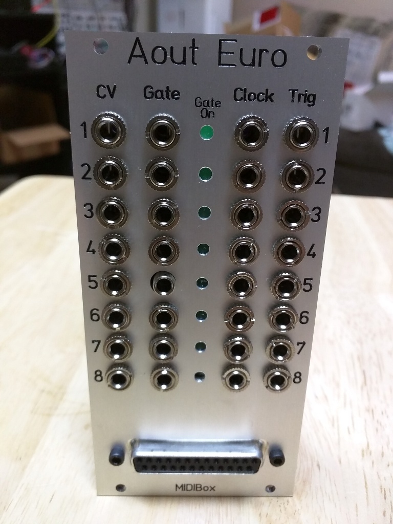
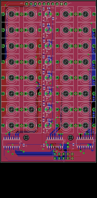
So it is time to offer a bulk order of these boards. This will be a PCB only set consisting of the DOUT/Jack board and the Aout module that mounts on the back of it. I could also offer this with the liner driver receiver if there is interest for it and possibly a PCB euro panel.
The module does this:
3x DOUTs for 8 5V gates, 8 clocks, and 8 Triggers
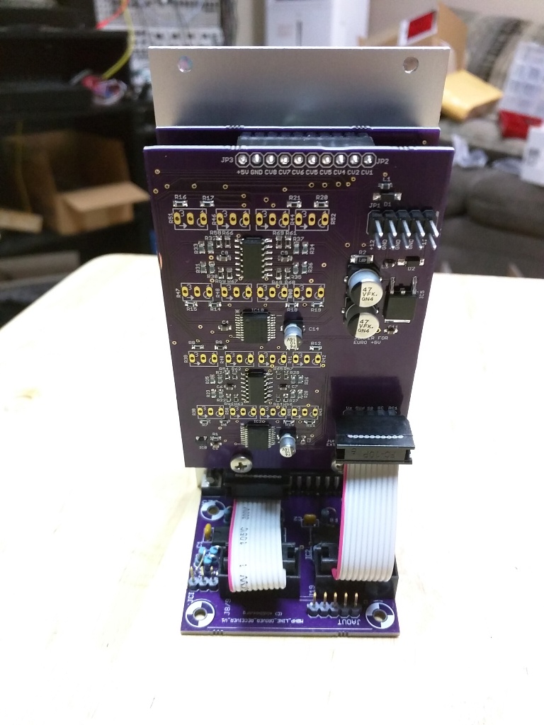
8x CV Channels via the MAX525 DAC with the Bipolar offset option.
There will be an additional DOUT/DIN header on the board for linking to a Euro TPD module down the line
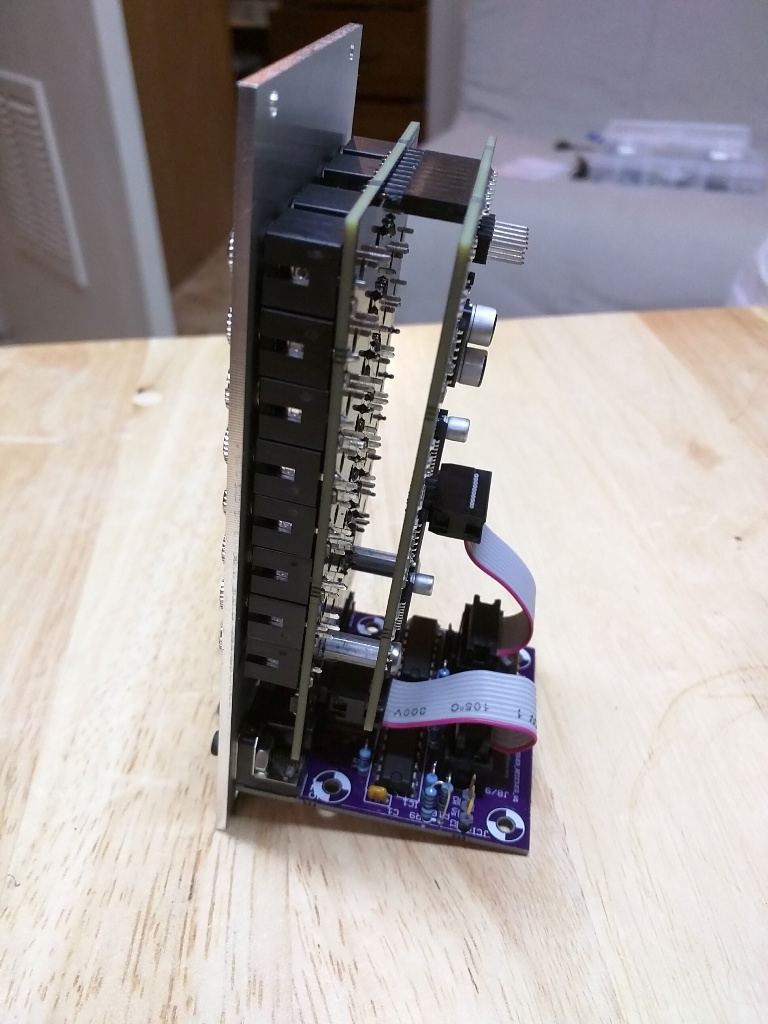
The module is provisioned to be powered via 10 pin euro power header with the +5V being supplied either by the module itself or from the line extender. I tested both ways without noticing a difference but do recommend that it be powered internally.
Pricing will depend on how many people order but expect ~ $30 for the set of just the DOUT/Aout boards
Sign up here: https://goo.gl/forms/1OGckjLWgzbw1sTq2
Also, a warning: This is an all SMD board, 0603 size passives, SOIC opamps, and the MAX525s are SSOP size, if you dont have experience with soldering parts like that, I recommend getting some practice boards off ebay until you are comfortable. This is not a beginner's surface mount project.
Boards will be made by PCBway. I can get ENIG plating or leaded HASL. Leaded HASL is much better to solder to but is not ROHS compliant so input would be appreciated on that.
-
Yeah, there is only so much time I can throw at this. I'm about to give away the rest of my VFDs, I have no use for them
-
i was never able to get it to work
-
31 minutes ago, Psykhaze said:
..
Regarding SMD components, to me it should be avoided as much as possible. Most peoples aren't dealing easy with SMD soldering, and I'm the first. i know sometimes component size is an issue and the choice of having SMD components is also related to the fact it's sometimes not available DIP/PDIP package. But in order to keep PCB assembly accessible to most of us , if DIP could be choosen, i think it should be better.
Imagine some noob buying some pcb+kit and missing his SMT solderings, ending in hating this precise way of handling. Just my thoughts.
..Couldn't disagree more. The sooner people move away from THT, the better. There is a whole thread worth of people at muffs that never held a soldering iron before that made up Mutable DIY modules successfully which are 0603 and have all sorts of fine pitch parts. If those people can do it, anyone can. SMD parts are available with better specs, more packing options, and there are many more parts to choose from. THT resistors/ICs/capacitors are going away, every year manufactures are dropping lines and there is less and less to choose from. Besides, I much prefer to buy a reel of 5000 resistors that will probably last me for the rest of my life for $10 than having to restock parts every couple of weeks with THT.
More and more module makers are offering SMD kits and no one is really complaining.
There used to be a standard PCB size for midibox projects which was governed by the maximum board size in the free version of eagle but obviously things have progressed since then.
-
I say no wider than it needs to be. 14HP is just fine IMHO
-
0-10.68V by 4096 steps is 0.003V/ per step so it's reasonable.
Maybe 1 millivolt is embellishing it a bit but its pretty close
-
and calibration is done. Tracks like a champ, within a millivolt from 1.000 to 8.000 V. Tomorrow, the workout
Also worth mentioning: I tested using bus power (+5V from the SEQ) and powering the +5 from the onboard supply and did not see any difference in noise on the scope. Oddly enough, the liner driver receiver gets pretty warm when powering it that way (it still gets +5 from the core regardless of how the other modules are powered). I'll leave the headers on the boards but at this stage, I recommend everyone use the onboard +5V supply
-
Ok, preliminary testing done for the Aout portion and seems to work. Need to calibrate and give it a work out.
-
Yep. We need to chat..
-
the corrected boards are on their way from OSHpark so next week I'll finalize the testing
I was thinking down the road a bit and adding a DOUT/DIN header so you can expand that chain to euro TPD module..
-
And panel is in, everything fits!
-
 3
3
-
-
the boards are not open source
-
In a mixed sid/swinsid, yeah, deal breaker. Unless the level issue is specifically addressed in this rev, i wouldn't bother. Waveforms/resolution/whatever make no difference if it's half the volume of the real thing
-
keep in mind that the output level is WAY lower than the real deal. Deal breaker for me, I returned mine.
-
prototype boards are in and despite a DOUT order snafu, everything is working on the Jack board (the DOUTx3). Will try to stuff the AOUT board and have it tested this weekend..
-
there is no cable out of the DOUT, it's integrated into the board and hardwired (see above)
It's not a big deal, this was the prototype board. Important thing is that it works.
-
so SI becomes SO and RC becomes open?
-
Success! Thanks Andy!
For anyone else:
The additional gate/clocks/triggers are SR 3,4,5 respectively on the SEQV4 with WIlba's control surface.
I am backwards on my wiring however, what I thought was gate/clk/trigger 1 is in fact 8, can this be remedied by messing with the cable or do I need to redo the board?
-
ok,
tried 1,2,3 and that messed up the LEDs on the CS. I assume I need to shift those numbers since the CS SRs are 1,2,3?
-
>I think you're misinterpreting the config file
That goes without question :) This is uncharted inferiority for me, I'm not very cody..
That makes more sense. So the SRs at the end of the Dout chain (past the CS,into the line extender, then out to the 595s) are sequential per 8 outputs (i.e. the first 595 is "1" the second is "2" and so forth?)
Will a mirrored cable work for me? everything is hardwired on the PCB.
How about the J5 line, should that be off?
Revised 25-pin breakout port
in MIDIbox SEQ
Posted
What is the current draw for these parts? I'm seeing some pull here as well.. The receiver actually gets warm on mine