

Altitude
-
Posts
1,184 -
Joined
-
Last visited
-
Days Won
30
Content Type
Profiles
Forums
Blogs
Gallery
Posts posted by Altitude
-
-
yeah, been pouring over that info. Is all that consistent with your BLM? Kept thinking the bottom row had alt functions for some reason..
What is the spacing between button centers? I'll draw up some labels for people with a label maker
Thanks for your hard work! It's amazing this is finally a reality after so long.
-
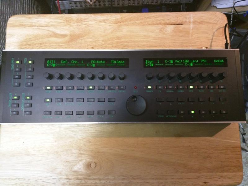
Done!
Question: Where is a good guide of the left and bottom row controls? I really need to make some labels until I'm comfortable with everything
-
 1
1
-
-
Gotcha. Just make sure you check for shorts and polarity before you power up and you should be fine
-
1
-
-
no, ignore those labels. Those are for a C64 PSU that I dont use. I simply connect the + wire and - to those pins of a blank 7 pin DIN connector and use a +12VDC supply.
-
no, 6 and 7 in that diagram
-
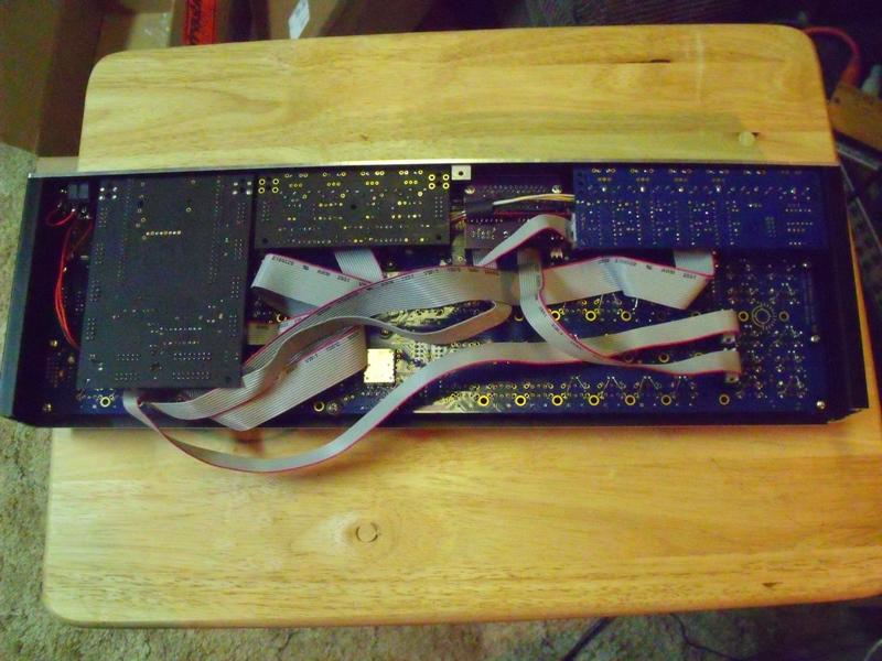
looks good. The two power pins you will use are the two inside pins of the DIN connector, I cant tell you which those correspond to on the board, I just plug the DIN connector in and checked the pins with a meter, one goes to ground and the other is connected to the "9V-11V" pin. Make sure your jumpers are in, follow my pic as a guide
-
sorry, already gone
-
you can use a standard linear regulator, no need to spend 13 quid on a fancy switching one, it wont get very hot.
2A will be plenty, I measured ~1.1A on mine using 12V (700 mA for the SIDS!)
-
1
-
-
Yep, that's how I have done it. switching 9V and 5V Recoms and a 7812 for the +12V rail and a 15V DC supply. You could forgo the 7812 and just use a regulated 12VDC brick but that's sort of putting yourself out there and any PSU fault could result in damage to the SIDs. The 7812 would provide protection from overvoltage. Triple check all your voltages before installing any chips
The wire in that pic was to power the backlights for the knobs on mine and is not necessary
-
The TI one is long gone, switched to the Recom R-78B5.0-1.5L
-
make sure you test them when you get them
-
that sounds like a broken sid chip, dead filter is the most common failure i've seen
-
woot. Chips are cheap, should be fun
-
that sounds weird, check the voltage when powered up. Switching supplies have load requirements so going too low can cause problems. For the one I just built, I used a 5V 2.5A wallwart that I cannibalized for an old USB hub, should be plenty. My seq draws all of 300 mA and that's with IIC, Midi I/O and port extender
-
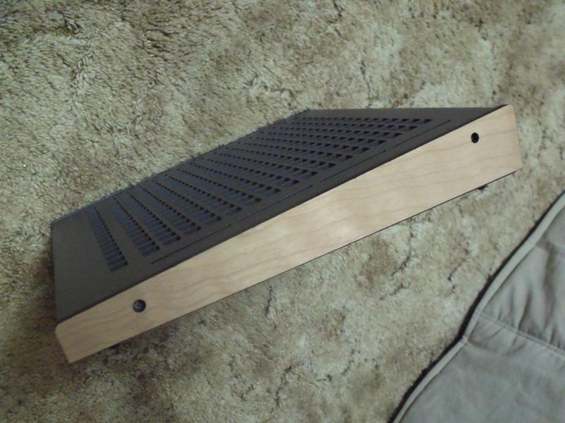
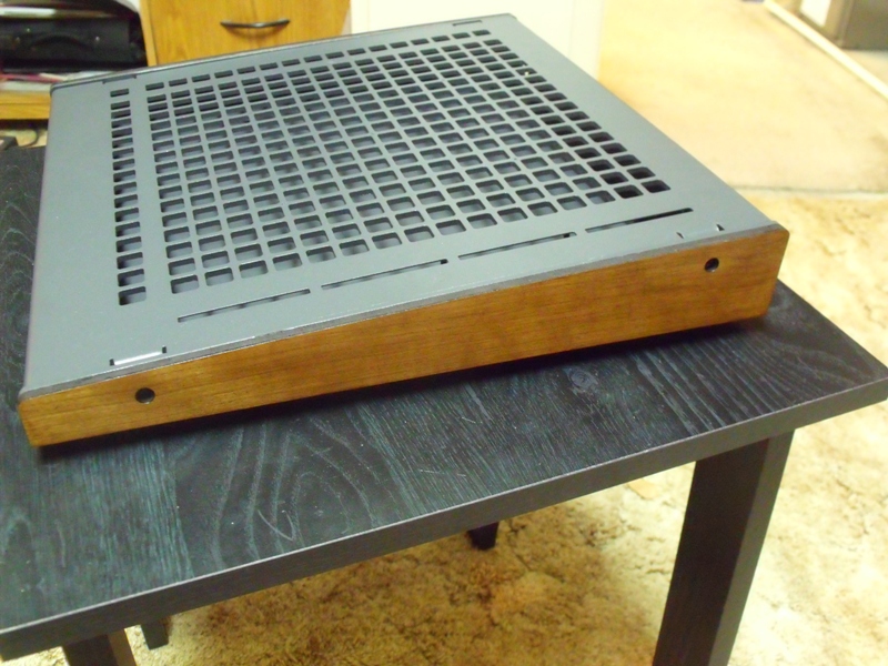
And wood is done:) I'll post the file if anyone wants it

-
we got wood :)
-
1
-
-
CAM expert but it's the same type of enclosure as Front Panel Express/Schaeffer offer. They do all the infill
-
that's everything. In hindsight, I wouldnt do the blind studs again, the accuracy of those was a little on the loose side and required some board convincing to get right, that would have lowered it $35
-
$300
-
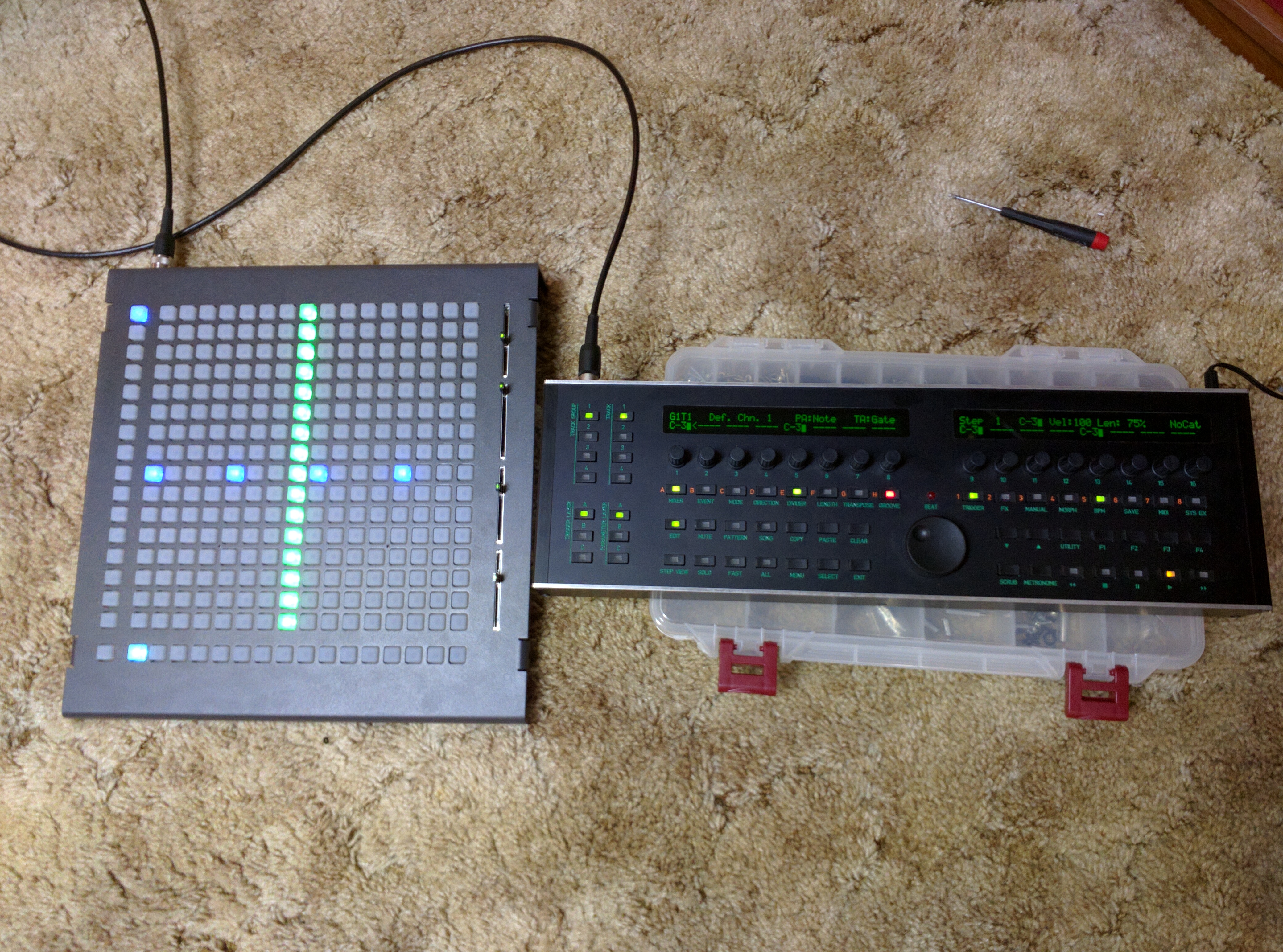
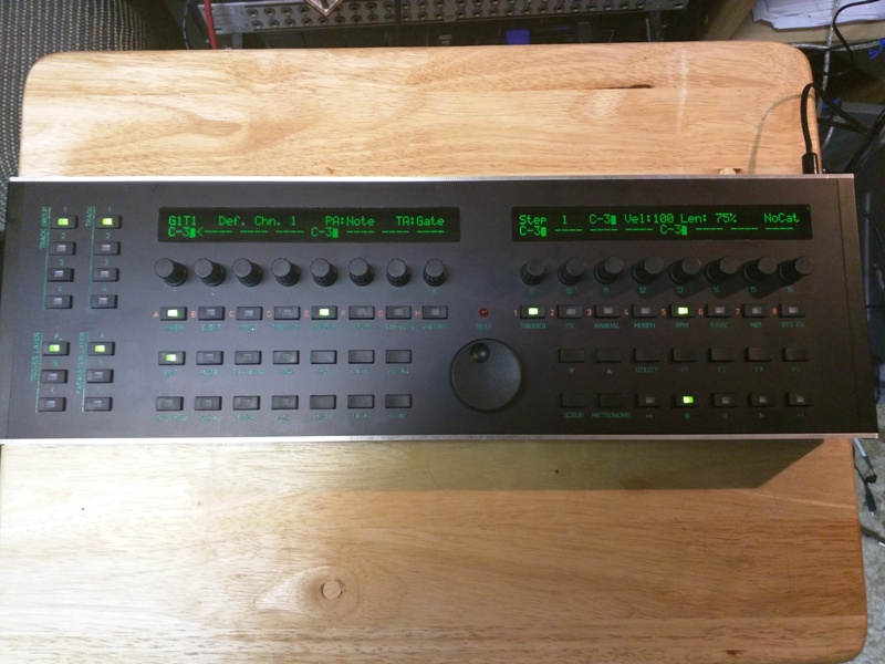
So I've been had this in the planning stages for a couple of years now and with the advent of the line driver and BLM, now was a good time as any so I got it done.
So this is:
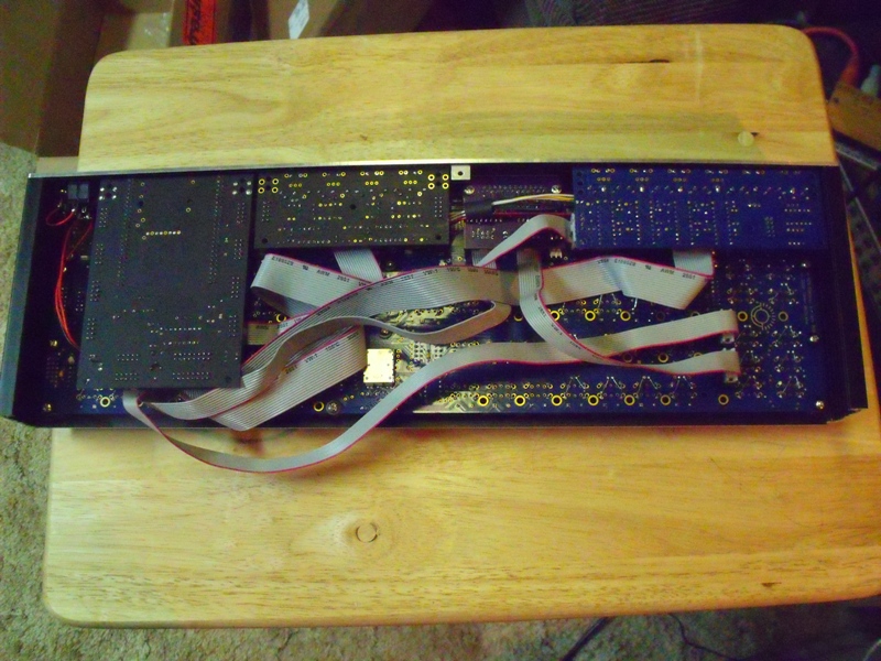
STM32F4 core
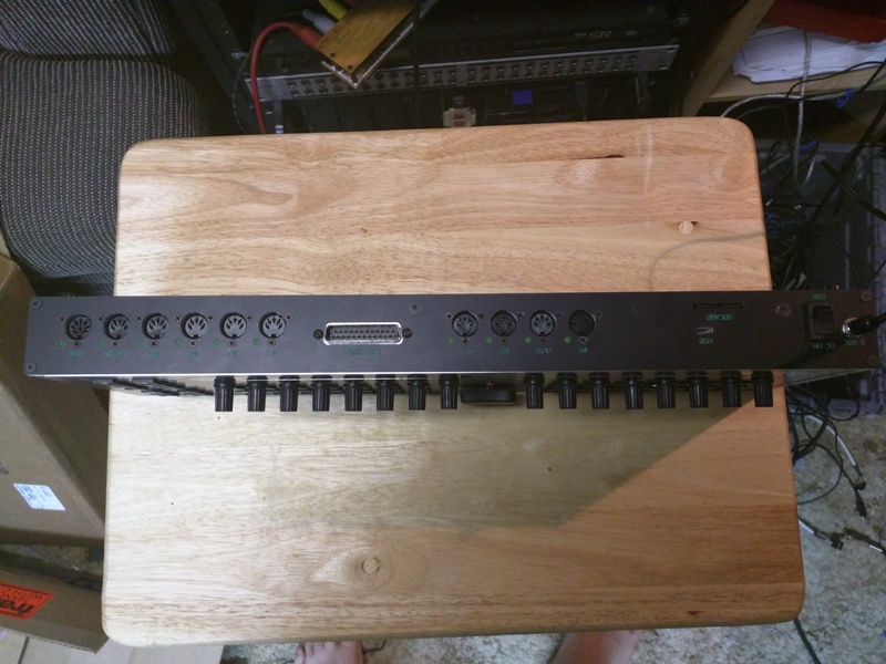
1x midi IO
1x Line Driver
1x quad IIC (BLM ready)I used the 3F Mec parts for the backlit buttons and hand wired LEDs (not that fun), Worked out well, it would be nice to have a rev of the CS board that does have them wired up, the other foot print does and the MEC footprint has the holes but they are not connected to anything
all in a nice 42mm thick CNC case
Total current draw: 300 mA

-
So I should be able just to use the out on the Midi i/o correct? so J11->midi I0-> Quad IIC BLM connector
-
So just to confirm: quad IIC blm port connects to J5B on the STM32F4 core?
-
Perfect. Thanks..
-
Question to anyone who's finished: whats the max current draw?

BLM 16x16+X build guide
in MIDIbox BLM
Posted
Ok,
All dressed up:
Here is the PDF for the ppl with label makers like PTouch (12mm wide clear)
http://misw.us/BLM_label_12mmX245mm.pdf