

Altitude
-
Posts
1,184 -
Joined
-
Last visited
-
Days Won
30
Content Type
Profiles
Forums
Blogs
Gallery
Posts posted by Altitude
-
-
Hows this supposed to work with no cutout for the LCD? Those mainboards are made wrong.
-
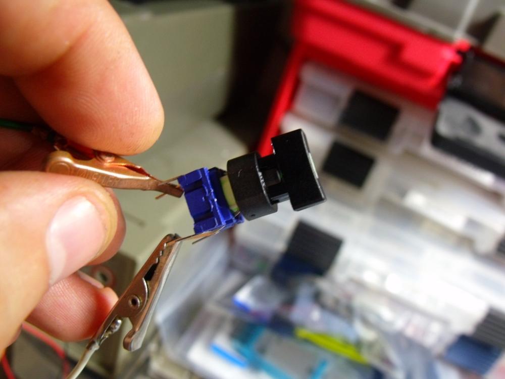
well not necessarily, the standard height with the tact and rectangular cap i show above is about the same as the TL1100 the the stock switch cap but if you need more (say you want to put a standard LCD under the panel, you need at least 14mm between PCB and panel for it to fit) you just add the spacer between the cap and the switch. There is a hole down the middle so the light still works fine.
It's always been a struggle to find buttons tall enough for a control surface where the LCD and all the controls are on one board and not have the bezel of the display poking out since the buttons are too short (i.e. Shruthi, P6, PreenFM etc). Personally, I cant stand the way that looks but there really weren't any options since everyone used the same tact switches
-
Good idea but those are a but on the small side
-
I figured they would be useful for someone
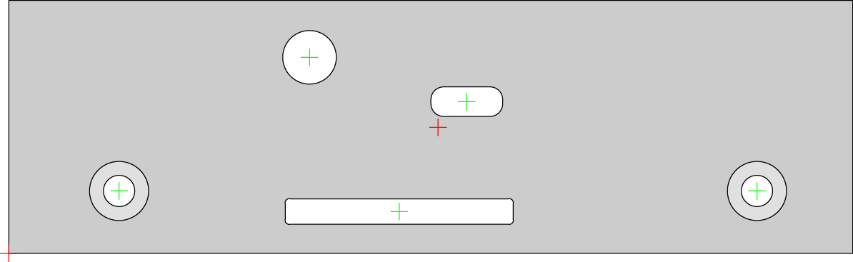
STMF4 Core cutout. This requires a 2mm washer to go between the threaded terminal (mouser PN 534-7700) and the panel since the discovery board and core board do not sit in the same plane. This also recesses the SD card somewhat but seeing that it does not get removed often, I opted for a small slot for aesthetics instead of a bigger opening to make it easier to get out
For the midi cutouts, you want to use SDS-50J midi connectors (http://www.cui.com/product/resource/sds-xxj.pdf) which have holes in them for M2.5 or 2-56 screws. The holes to the right are for activity LEDs
-
 3
3
-
-
I'm down for 30 clear and 10 data wheels
-
What about the 20k parts
-
woops, sorry. Too many blm threads. I do have the PCB
back on topic:
re: bat54/NPN
So you just stack the diode on top of the transistor?
-
Did you ship everyone's PCBs? I expected to get mine with the case
-
ah, good call. I had the filter on for clock in midiox. That was it :)
-
So I noticed something when testing all my modules today, with the STMF4 core and 1 midi I/O connected, when an event is routed to the IIC ports, all the LEDs come on instead of just the one for the port in use. The data is going to the right port (and only that port) but all the LEDs come on regardless of the port assignment. Is this software bug?
-
so what's the scoop on cases?
-
hence this post :)
-
Located in the USA
-
what do you have left?
-
1
-
-
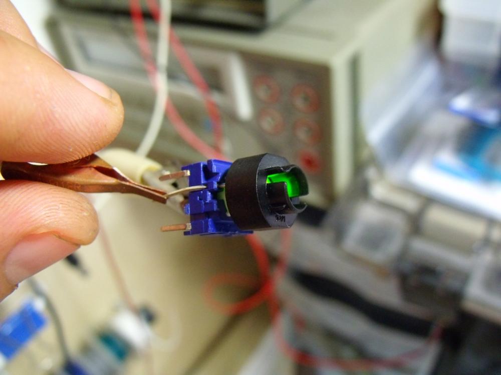
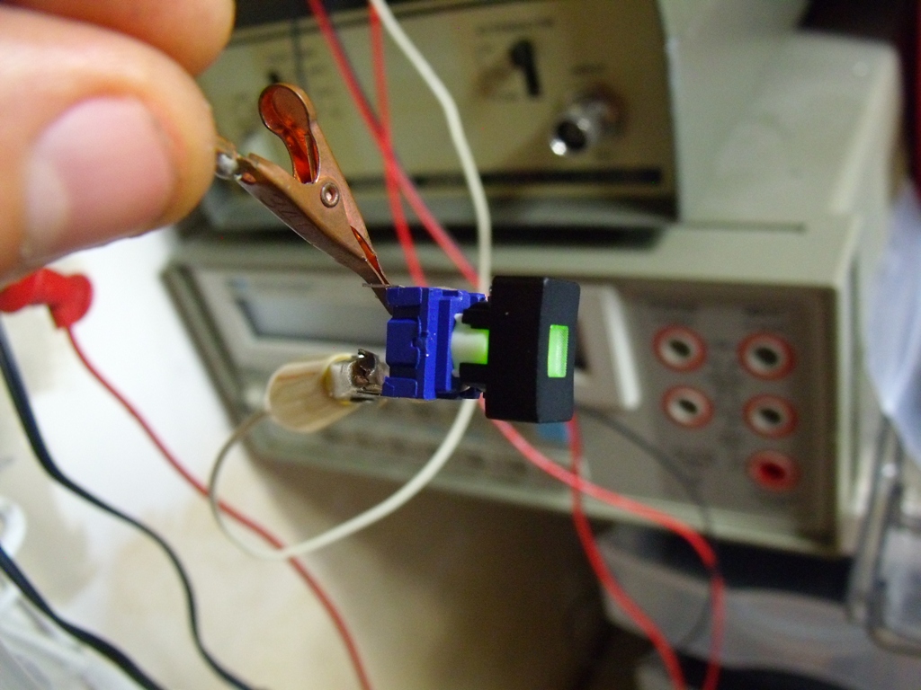
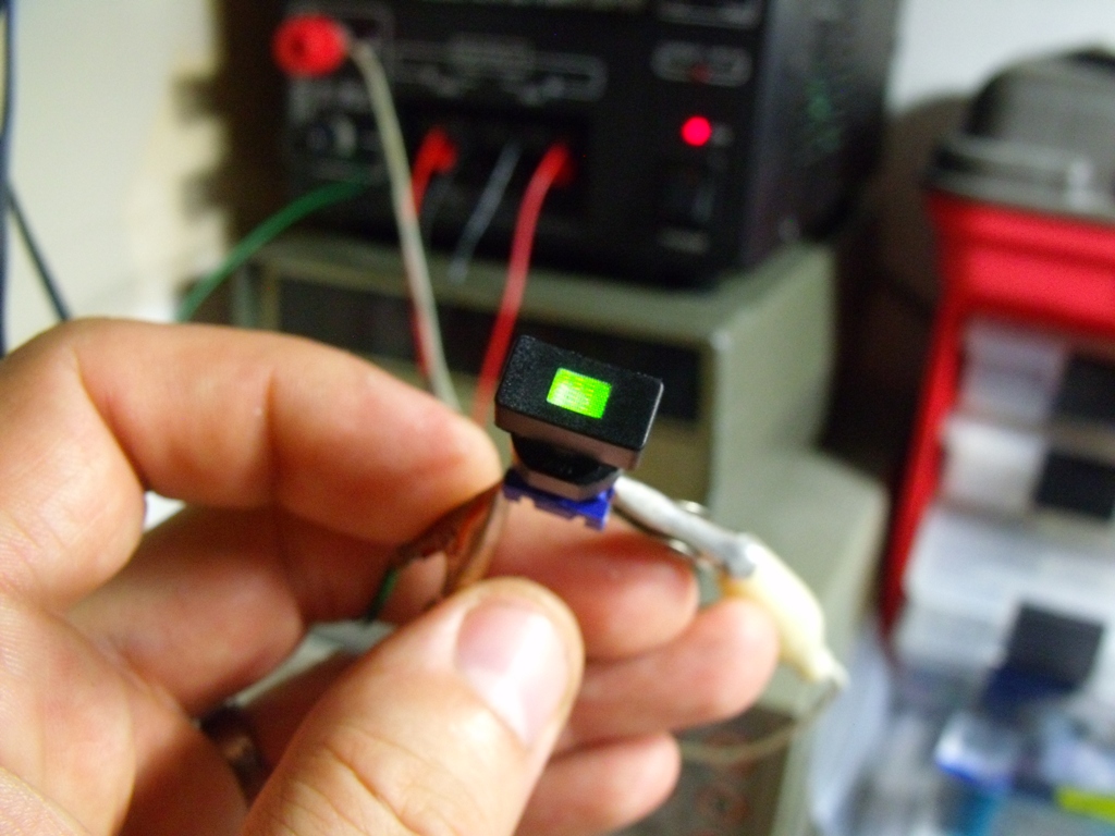
That's the switch and that's an insanely good price. They are $2.7 in the US
I used 1Q096 for the clear windowed ones and 1P09 for the solid (both black)
Documentation is really bad for the 3F switches for some reason and the site you linked has the best one: http://www.soselectronic.com/a_info/resource/h/MEC/3F.pdf . You need to be careful when choosing those since they make the same style cap for all the various switches they make and you need to make sure that you have one for the 3F or 4F switch
-
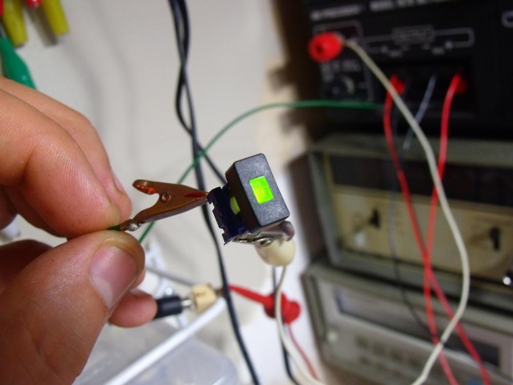
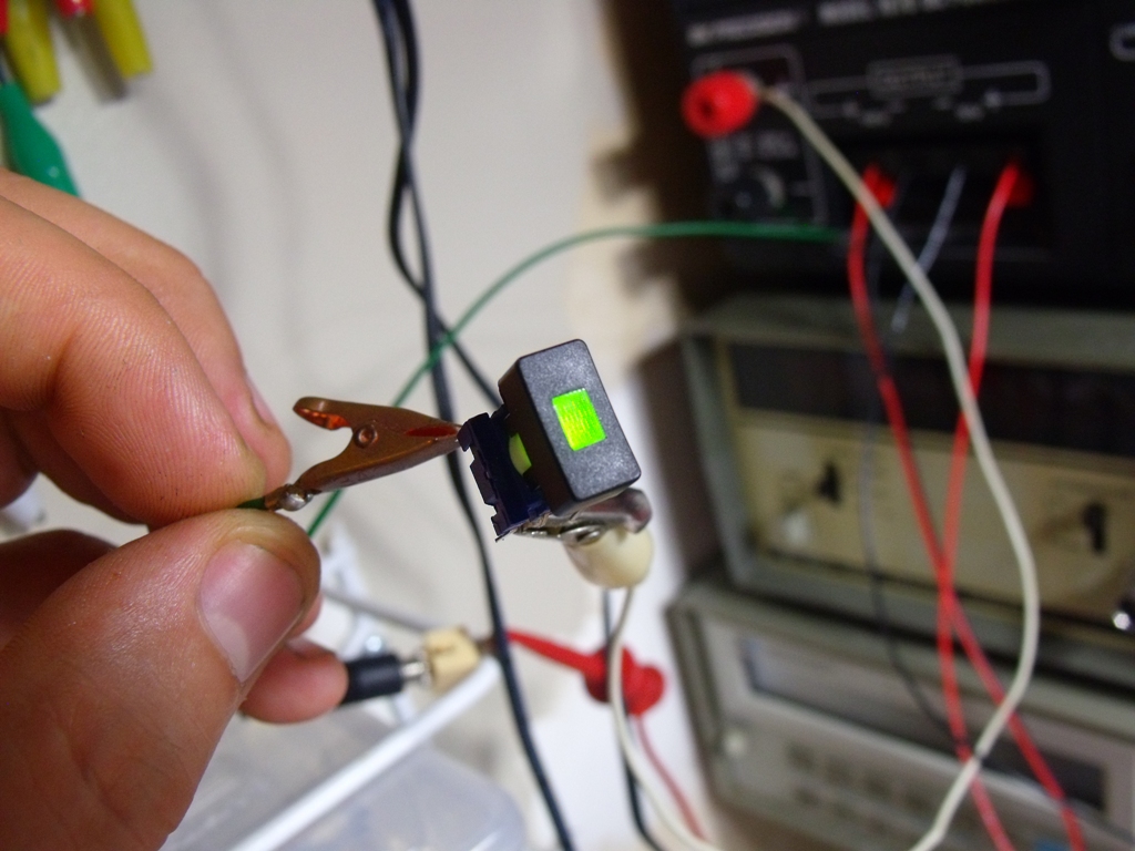
yep. that was the plan
-
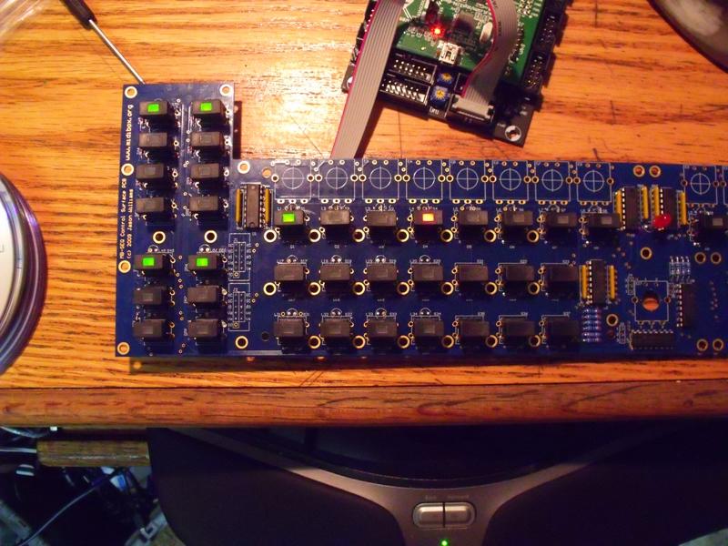
and the results
-
1
-
-
-
totally forgot about this thread, sorry. My case file and graphics files are attached. The two illustrator files differ with the holes for the screws to attach the PCB to the front panel. I recommend using the one WITHOUT those holes, its better to countersink the screws and cover them with the sticker. You can mess up the sticker if you screw down on top of it
-
might take you up on that coupon, have some 4 layer stuff that needs to be fabbed
-
 MEC Switches!
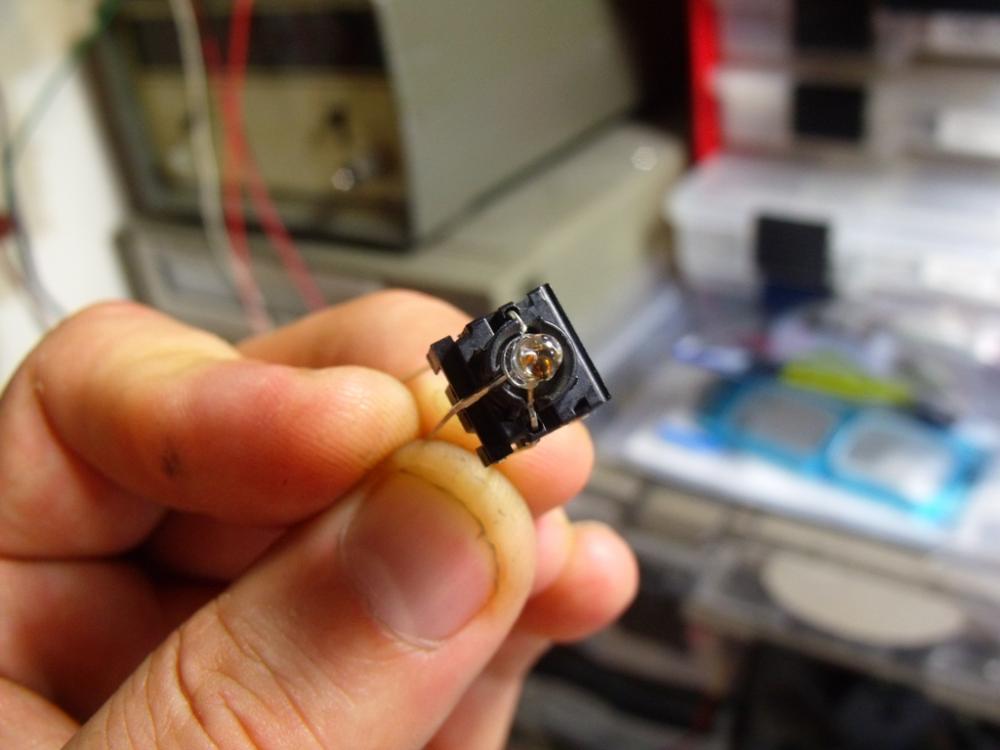
You want the 3FTH9 tact, this takes TH LEDs and you can even modify it to use 3 pin ones (for the sequencer).
The extenders are 2S09-5.0 (5.0 being the length in increments of 1 from 5.0 to 10.0)

-
wow. Interesting development
-
duh. keep thinking 7 pins for some reason
-


BLM 16x16+X PCB and case order [CLOSED/waitlist]
in Bulk Orders
Posted · Edited by Altitude
sweet. Looks like laser cut wood sides time (make it sound better)
Is there a drawing of the case? I need the side profile only