Flying Panther
-
Posts
91 -
Joined
-
Last visited
Content Type
Profiles
Forums
Blogs
Gallery
Everything posted by Flying Panther
-
Nice one! The display and knobs below it look nice this way :)
-
I wouldn't do the grey lines personally, as that would give a strange contrast between the (highly contrasting) white on black everywhere else. Maybe make them the same blue as in the logo (or change the logo blue to the same one as you use for the lines) or maybe white? That way the lines might 'fit' a bit better, because the color comes back somewhere else on the panel. A border around all blocks might look nice.. :)
-
Just a quick suggestion for the controls under the display, maybe you like it, maybe not :) Also, I would centre-align the (I think they are ventilation) holes under the matrix to the block they are in. And the blue lines, are they just for reference? If not, have you thought about removing them? In my opinion the panel looks much nicer without the lines.
-
I've put myself down for one as well. Looks like the third lowest (MINIMELF / DO-214AC / DO214AC) would be able to share the same soldering pads. Also those pads look big enough to confidently solder them without getting scared for SMD ;) As for the color, I'd be happy with an 'average' green board with white silkscreen, as all other boards I orderd up untill now are that way.
-
I'm interested as well! I'm not even near designing the control surface, but a nice PCB for the matrix will make things a lot easier when I get to it :)
-
After reading a bit more into this, I get the idea behind the crowbar circuit. That might be a very useful safety measure. I also get the diode around the regulator (although the datasheet states that when capacitors behind the regulator arent over 10nF the diode isn't necessary, it might not hurt to put it in either). What I don't really get is the latchup protection. The only application of a diode that I found was between two different power sources of a CMOS, not between the GND and V+. Not that I'm questioning your setup, but I'm trying understand what you did. In this case (with a diode between GND and V+), when GND accidentally gets a voltage spike of more than 0.3V, it will flow to the V+ rail, right? But what if that is, say in a worst-case scenario something above 10V. Then you have 10V passing from GND to V+, which might damage the SID as it can only withstand 9V. Wouldn't it then be much safer to leave the 10V on the GND-rail and let that current blow a fuse or something? Also, will the diode do it's work properly when fitted right after the PSU? In all documented cases I found, the extra components were fitted right before the CMOS that needed protection from latchup. Could you explain the phenomenon a bit more and as well your solution to this? Because I feel like I'm missing some key point in the whole latchup matter. :)
-
It's a pity when a SID turns out to be broken.. When combining the two SID's you have to keep in mind that they have a different sound. It depends a bit on the way you want to use the sammichSID. If you want it to be dual-mono, I think it is not a problem and soundwise you even have more 'options'. But in stereo mode I would prefer the two SID's to sound as close as possible. Addition: If you are going to put in a 8580, be sure not to only switch the capacitors, but als make sure you run the 8580 on 9V. The 6581 uses 12V which will fry the 8580. Thinking of it, I'm not sure if the sammichSID is capable of supplying different voltages to each SID, you might want to check that first!
-
If you're sure you don't need that extra one yourself, that would be perfect! But I don't want to be responsible for one of your projects not having a power supply.. :angel:
-
I just found this topic and had an interesting read through all the various options mentioned. I was struggling with how to make the power supply and actually, the project hasn't moved from the shelve since then. The idea of a switched power supply appeals to me, as three different transformers (as I was planning) combined with maybe a bit more safety (the crowbar-circuit mentioned here earlier seems like a decent option) will take a lot of space and money (which kept me from building one). I researched a bit more on opinions for switched power supplies and found that there are people who praise technology for making switched power supplies that are equally noise-less as linear power supplies. I also found people who throw all switched power supplies away and replace them with linear ones, because the switched ones are evil. So that doesn't get me any further. I know that the SID isn't whispering quiet and that if synth manufacturers use switched power supplies all the time, maybe I could do so as well. Naturally they have budget as a heavy factor to consider, but even synths like the Andromeda and Prophet 08 use switched power supplies if I recall correctly.. Building my own switching power supply is not an option, I doubt that I can design something with less noise than a stock power supply, even when using a higher switching frequency, as layout and choice of parts seem to be a bigger issue than with a lineair design.. Therefore I lean towards the RPT-60 at this moment, together with a 7809 and some extra smoothing caps on all lines. I'm going to give it some thought during a good night's sleep... Edit: not sure why I wrote all of this down. Seems to be an elaborate way to show my enthousiasm for this topic.. ;)
-
acrylic front backlighting for Midibox SID V2?
Flying Panther replied to rvooh's topic in MIDIbox SID
I think it might look really nice (can't say exactly, as the pictures are leaving things a bit to my imagination), reminds me a bit of the old (70's?) calculator displays (with those bright green characters) and some other electronics like on the picture.. -
Thanks for the elaborate answer :) Solidworks really is a nice piece of software to work with imho, nice to see that companies can use it aswell.. Saves a lot of effort on converting things to the right format!
-
I'm curious where you will get your panel made? As your Hu-Mon panel looks very professionally done as well ;) And does the company do everything (lasercutting, bending the sheet-metal, powder-coating), or do you work with various companies to get this done?
-
Great build! I only think that if I'd buy one, I never get to finishing my 8x sid ;)
-
soldering iron upgrade time, what are you using?
Flying Panther replied to bhc303's topic in Miscellaneous
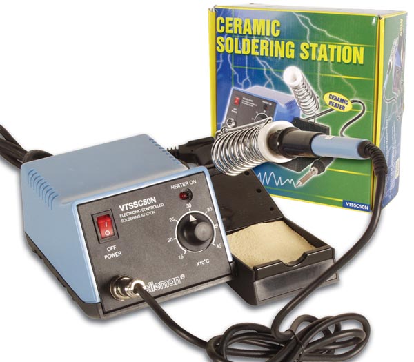
I have a Velleman VTSSC50N, not cheap but not very expensive either. I'm very happy with it, it does everything I want it to do. For the soldering work I do (which is not that much) a more expensive digital controlled soldering station would be an overkill. -
As Beyerdynamic is located in Germany, you might want to try using their own shop / support department. (http://shop.beyerdynamic.de or http://www.beyerdynamic.de/en/home/service.html)
-
Wondering about PSU circuit / 78xx behaviour
Flying Panther replied to Flying Panther's topic in Testing/Troubleshooting
Thanks!! I think I'll draw a final schematic, and then buy me some parts and see how things work out :) -
Intresse in MEC Multimec switches (evt. met LED)?
Flying Panther replied to Flying Panther's topic in Nederlands
Enigszins aan de late kant, maar voor de volledigheid toch nog maar even een antwoord. Ik heb de switches zelf nog niet besteld, aangezien het hele project wat vertraging opgelopen heeft. Ik heb destijds wel van de bovengenoemde switches en kapjes een sample aangevraagd (en netjes verpakt ontvangen) bij APEM Benelux: http://www.apemswitches.be -
Wondering about PSU circuit / 78xx behaviour
Flying Panther replied to Flying Panther's topic in Testing/Troubleshooting
Those mica insulators look really nice :) Might be worth using them as well when only combining heatsinks for 78xx's to avoid groundloops. (Maybe keep one 78xx un-insulated to have the heatsink grounded). Regarding to the power supply, I think I'll stay with the three transformers. Still two things that I'm not sure about. What about the fuses? Will 0.1A be enough? When you convert secondary current to primary current, you'll get about 70mA, I've read somewhere that fuses should 'work' at about 75% of the total allowed current, so for a 0.1A fuse that would be 75mA, which is close enough to the 70mA I have. But I don't know if there will be peak currents when for instance powering on the circuit that'll go over the 0.1A rating and blow the fuse. Or should the 0.1A fuses be okay (in theory)? And what about the ratings for the capacitor on the 5V line? is 4700uF enough for a maximum current of 1.5A? or should I better go for 6800uF or the 4700uf / 2200uf in parallel? Editing reason: nF / uF is not the same ;) -
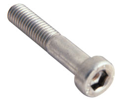
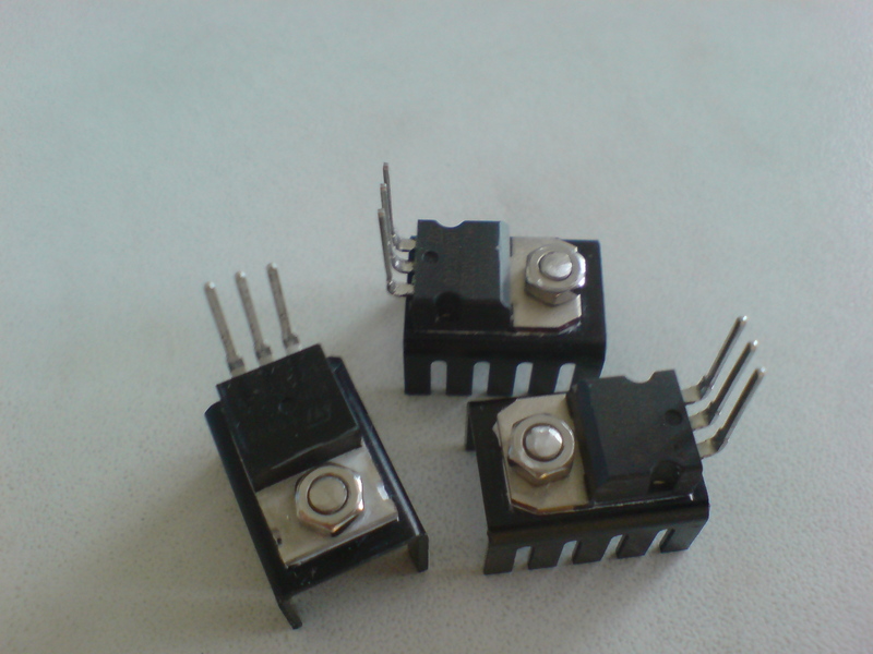
If you're going for visible bolts, I myself like the (also non-countersunk) ones used on the Korg Electribe mkII's. Korg used stainless (or at least stainless colored) ones on the electribe, but black ones are available as well. (The ones on the picture aren't exactly the same as on the Electribes. I the ones used by Korg have a higher 'head'.)
-
Wondering about PSU circuit / 78xx behaviour
Flying Panther replied to Flying Panther's topic in Testing/Troubleshooting
After reading both your comments on the considerations, I strongly lean towards the transformer-based power supply, and not using switching power supplies and/or toroid transformers. The advantages over regular transformers are obviously not that high, and still additional regulation / smoothing is needed. About the three transformers, I agree that it is a lot of transformer :P I'll let that comment sink in a bit, maybe I can find a solution to regulate 9V out of the same transformer as the +12/-12 without disturbing the equal loads and without needing a transformer that is supplying above 1.7A. Great idea! We can plug in however we like (no earth-pin to secure that you'll always plug in the same way), so I'll take that suggestion. Switching one side off should do the trick (even when plugged in backwards), but for safety-reasons it's still better to switch them both. Makes me wonder though, should I fuse both sides as well? *makes note to self to tripple-check pin-outs on the datasheet and connections on the board* I'll even that one out with the comment about over-rating the parts ;) Thanks :) A lot of planning was involved to fit it all on the board. Interesting idea! Heatpiping is a nice way to move heat through a place where more cooling is possible. Although I don't think that will work if I connect the 7912's heatsink to the 78xx's (if I understood lylehaze correctly) -
Wondering about PSU circuit / 78xx behaviour
Flying Panther replied to Flying Panther's topic in Testing/Troubleshooting
-
Wondering about PSU circuit / 78xx behaviour
Flying Panther replied to Flying Panther's topic in Testing/Troubleshooting
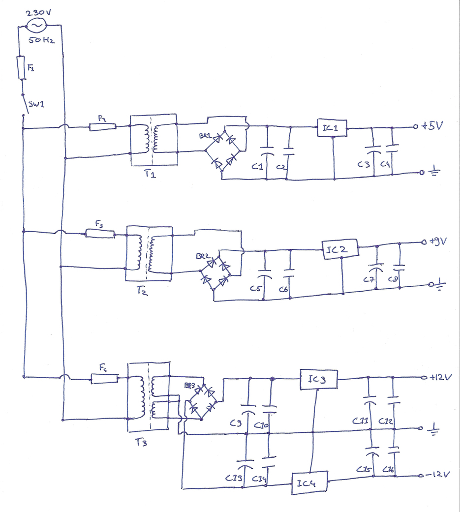
I have combined all the thoughts I had and information I harvested (from the MB forum, wiki and some other sources) about power supplies and components and the attached schematic is the outcome (please see attachment). The following parts will be used: SW1: 250V Power Switch F1: 250V 6.3A Fast-Acting Fuse (standard fuse already in the power-connector, replace with a 230V 0.3A?) F2: 250V 0.1A Fast-Acting Fuse F3: 250V 0.1A Fast-Acting Fuse F4: 250V 0.1A Fast-Acting Fuse T1: 230V-9V 16VA (1778mA) Print Transformer T2: 230-12V 16VA (1333mA) Print Transformer T3: 230-2x15V 16VA (2x533mA) Print Transformer BR1: 2A 400V Bridge Rectifier (2W04G) BR2: 1.5A 400V Bridge Rectifier (W04G) BR3: 1.5A 400V Bridge Rectifier (W04G) C1: 4700uF/16V Electrolytic Capacitor (maybe even 6800uF/16V or 4700uF/16 and 2200uF/16 in parallel?) C2: 330nF/50V Ceramic Capacitor C3: 10uF/50V Electrolytic Capacitor C4: 100nF/50V Ceramic Capacitor C5: 4700uF/16V Electrolytic Capacitor C6: 330nF/50V Ceramic Capacitor C7: 10uF/50V Electrolytic Capacitor C8: 100nF/50V Ceramic Capacitor C9: 2200uF/25V Electrolytic Capacitor C10: 330nF/50V Ceramic Capacitor C11: 10uF/50V Electrolytic Capacitor C12: 100nF/50V Ceramic Capacitor C13: 2200uF/25V Electrolytic Capacitor C14: 330nF/50V Ceramic Capacitor C15: 10uF/50V Electrolytic Capacitor C16: 100nF/50V Ceramic Capacitor IC1: 78S05 Voltage Regulator IC2: 78S09 Voltage Regulator IC3: 7812 Voltage Regulator IC4: 7912 Voltage Regulator I think some explanation is required, maybe not so much for the schematics, but more about the thoughts behind them. First of all, the power supply needs to supply 5V (1A-1.5A for cores, SIDs, LEDs and LCD), 9V (800mA for SIDs) and +12/-12V (200-300mA for op-amps in a mixer circuit and maybe some AOUT modules). I'd like to have the 5V on a separate transformer, instead of using the voltage supplied by the 7809 for the 9V rail. This because currents drawn from the 5V rail are relatively high, and all that current has to run through the 7809 as well. The +12/-12V circuit works best with equal loads on the + and - rails. Therefore it's best to give them a seperate transformer as well, and not regulate the +12V down to +9V for the SIDs. This means the 9V rail gets a personal transformer, which I don't really mind. It's a bit bigger using 3 transformers, but I'm not planning on a small case so that will be fine. Then, I also want the transformers not to run at full capacity. Therefore I chose the ratings a somewhat higher, so they will run at about 2/3 of their capacity and have a safe, happy and hopefully hum-free life :) For the rest of the components used, I tried them to match the transformers, not the actual current drawn from the circuit. This way all components have some 'safety headroom' and might make me sleep better at night. Also I don't have to worry about adding some extra buttons / LEDs, since I have enough capacity anyway. Also I have some other considerations: 1st: what about (more expensive) toroid-transformers? They are said to be better than regular transformers when working with audio, because they induce less ripple/hum. Is it worth looking at those (and redesigning the scheme, because 3 toroid transformers is too much), keeping in mind that ripple and hum is already reduced (a lot) by the regulators and capacitors, and knowing that the SID is noisy anyway? 2nd: Why not save me all the work and buy a nice switching power supply (for at least the 9V and 5V rails) I came across a while ago on Mouser. Judging from the datasheet and the amount of capacitors on the board they are regulated quite well, but I also read a lot about more high frequency noise. They are a bit more expensive compared to transformers, but also save parts and work. However when additional ripple reduction should be needed, the same amount of work and more money is involved, hence it's not worth it. Still not sure though... Pfew, that was a whole letter, if you're still reading: thanks!! All comments and opinions on the above are welcome :) -
Wondering about PSU circuit / 78xx behaviour
Flying Panther replied to Flying Panther's topic in Testing/Troubleshooting
That's a fair point. I guess I couldn't return them anyway.. :P I switched in and output pins (which made a complete mess of the whole board..) and now got 5.20V, 8.98V and 11.89V. That's like it should be, so the board now works as it was intended. You're probably right.. I already had some ideas, so I better put some more effort in those ideas and have the power supply done (instead of fixing this board with a properly regulated 5V). I think I'll have some questions about the "to be designed" power supply, but that's something for 'Design Concepts' I guess.. But first, there's more reading to do :) -
Wondering about PSU circuit / 78xx behaviour
Flying Panther replied to Flying Panther's topic in Testing/Troubleshooting
Thanks for the in-depth reply! About the regulator in the 5V path, that is something I completely forgot about when changing from the C64 adapter supplied 5V to a 5VDC wallwart. I have to reconsider that part, thanks for pointing that out! The plan was to use this simple board (with C64 adapter) to test the Core and SID modules when they are completed. When I get to the enclosure and control surface (as I know by then what currents are pulled from the power circuit), I want to make a transformer-based power supply that convert 230VAC to a lower value (15 or 12V) and then regulate those voltages to the needed 12, 9 and 5V. Do you suggest adding a 5V regulator also for these 'temporary' purposes? Or could I leave this for now and do it right when making the transformer-based power-supply? I used a resistor with the LED, but somehow I seem to have forgotten about it in the schematic (I drew this schematic after I made the board, since I figured no-one would have understood my hand-drawings :P). About the voltages, when I measured between the 78xx output pin and center (which is connected to the common ground), I read the same voltages (13.3V and 11.1 V). But I also discovered something else (when closer inspecting the 78xx in and outputs) that is a bit more trivial. I switched the in- and outputs of all 78xx when soldering them onto my board. That probably also explaines why they generate so much heat, while no current is drawn from the circuit. I'll try to fix that and measure everything again. Hopefully that fixes my problems ;) -
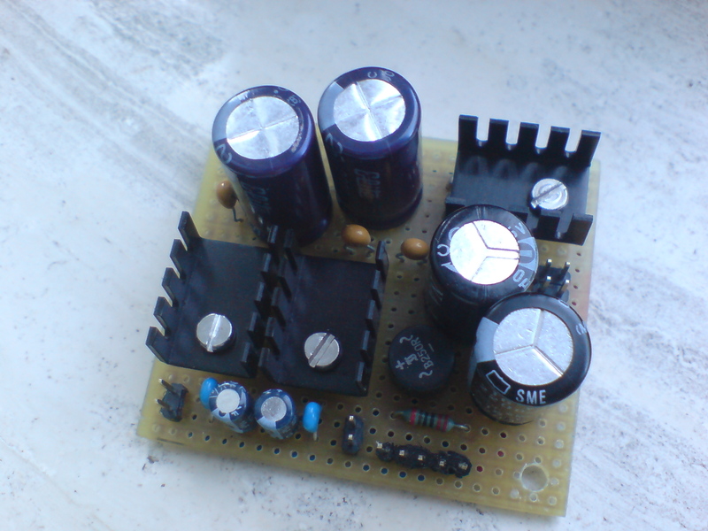
I was about to test my 'optimized PSU' board (for a MB-SID) with the C64 adapter, but the C64 adapter was kind enough to fail on me. Therefore, I changed the DIN-connector with two connectors that will fit standard wallwarts. Schematics from my PSU-board are attached (Addition to the schematics: The capacitors right after the bridge rectifier are 2200uF/25V (electrolytic) and 330nF (ceramic). Also the capacitors between the 15V and 7812 / 7809 may not be essential, but that was something I realized after soldering the board.). I also managed to find a 5VDC and a 10VAC wallwart adapter. The 5V one can deliver about 1A and delivers 5.20V exactly. The 10V one however can deliver about 700mA (which is not enough for all 8 SID boards, but enough for testing purposes), but gives me 12VAC when I measure it. This causes the (heatsinked) 78xx's in the power circuit to get very hot (which isn't strange, because the 7812 needs to dissipate 17-12 = 5V and the 7809 even more, 17-9 = 8V!) When the power is switched on, the voltage of the 10V adapter drops to about 11,5V, which seems normal to me, since it was made to deliver about 10V. What I found to be strange is that the voltages after the 7812 and 7809 read 13.3 and 11.1 respectively, where I expected it to be around 12V and 9V. The 5V output reads 5.16V so that's correct. Is this because the 78xx's get an input voltage that is too high? Or is it because I'm not drawing any current from the circuit, and will the voltages lower when I connect some of the SID boards? Or did I just mess up the schematics and did something else wrong?