rvooh
-
Posts
105 -
Joined
-
Last visited
rvooh's Achievements
MIDIbox Addict (2/4)
0
Reputation
-
LoopA V2 Introduction, Features & Support Thread
rvooh replied to Hawkeye's topic in MIDIbox User Projects
Well.. that would work, but seems very convoluted. I'd have to dive into the code to see what is technically making it impossible to just always send clock, I still think that's the most compliant and accepted way of doing things -
LoopA V2 Introduction, Features & Support Thread
rvooh replied to Hawkeye's topic in MIDIbox User Projects
For example, a TB-303 needs to be "stopped" to program it. But when clocked with dinsync it will "freeze" the moment it doesn't get any clock. The only way to program it when it is slaved to a device (= when a cable is in the dinsync input) that doesn't send clock when idle, is by yanking out the dinsync cord (which is really not practical, nor recommended as this is a fragile connector). My main sequencer (Squarp Pyramid) sends clock when idle (it also has a setting to disable it for people that don't want this). Actually most gear I have does it. One exception is the Alesis MMT-8, exactly the device I was hoping to replace with the LoopA, which I now have to use when a dedicated external clock for this reason. -
LoopA V2 Introduction, Features & Support Thread
rvooh replied to Hawkeye's topic in MIDIbox User Projects
Thanks Peter for explaining. It's more about compatibility with old machines that need to be "stopped" for programming, but can't be programmed without getting clock (they will just freeze), and how certain clock convertors (dinsync) prefer constant clock. The Midi spec allows both, though between the lines they sorta recommend sending clock when idle. That's bad news for me though as I was planning on using the LoopA as a master clock in my small studio, and glad I asked before I started sourcing parts. Hearing that it's also like that on the SEQ V4 make me suspect that it's not something that could be changed easily in software. -
LoopA V2 Introduction, Features & Support Thread
rvooh replied to Hawkeye's topic in MIDIbox User Projects
Been considering getting the LoopA. Just one question: does the device also send midi clock when it is not playing? I prefer it like this, but a lot of devices don't do this and it's quite a dealbreaker for me -
I guess it's a slightly different part then :) I started modding the power supply of my mixed SID setup yesterday. I only have 15V, 1A.. Will that be enough? 8 sids, full control surface. My gut feeling says it's gonna be fine due to the higher voltage.
-
look at your picture, bottom right corner: the double line on the silkscreen is visible and the part is overlaying the pcb traces, which suggests the printed side is facing outwards. The legend for pin 1 is correct of course. in all other pictures, the parts printed side is facing inwards, the double line on the silkscreen is covered and the pcb traces are visible.
-
A while ago I did this mod on one MB6582 and it didn't work. Due to lack of time I didn't troubleshoot it, so now I'm doing the mod on another MB6582, double checking every step. One thing that confuses me is the pic in the initial post.. It seems to have the Recom part (V4) installed backwards. Compare to all other pics in this thread it is installed differently. Looking at the datasheet / pin 1 location, it does seem like the pic is wrong, or its another part/form factor. EDIT: End up building it like I expected worked fine.. Took the older mb, reversed it and bam, works too now.
-
Cool thanks for the advice guys.. Ordering parts as we speak.. Any advice on C3 voltage rating? The ones I have here are 16V, considering it's a mixed setup that may be too small?
-
How about the safety of this power supply? How will it respond to over/undervoltage, reversed polarity etc.. I'm considering to mod my MB6582 and those from 2 friends with this, but I want to make sure no SIDs get damaged if a mistake is made.
-
Thanks for the heads up
-
https://en.retrogamesupply.com/products/power-supply-for-commodore-64 It comes at a steep price point (€70.00) but it seems very much suited for use with the MB-6582 with much attention to safety: I'm planning to order a few (for myself & friends with similar build), unless anyone tells me not to.. I'm quite scared to use the original C64 psu and I don't want a bulky solution using 2 separate wall warts.
-
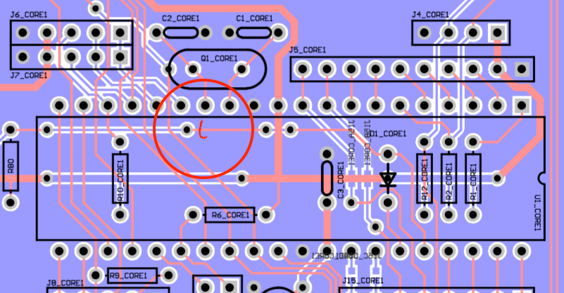
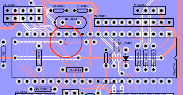
@TK. thanks a million.. my issue was a broken trace underneath PIC 1, causing discontinuity between pins #36 (see attachment). It's fixed now. probably happened cutting the ic-socket, more than 7 years ago.. doh! There wasn't any visual scratch to be seen though... Enjoy the beer
-
@TK. Wow, it's been almost a year since I followed up on this.. I still have the problem. All my cores have the latest firmware installed, and have correct device id's and respond when I query them with MIOS. Just the cloning wont work, and selecting SID 2..4 from the control surface says "CAN DISABLED". I have almost exactly the same pcb next to it, stuffed with same parts, which does not have the issue. Checked D1_COREx orientation, R80 and such. Removed all cores, checked continuity between D1_COREx's and their respective pin on the CORE Quite clueless atm. Hints are welcome :)
-
Did that fix the cloning or did it just place the firmware on it? Because you could keep the chips seated where they are and just move the jumper on J11.. It's strange that so many people have the same issue though (i found more topics like this on the forum) I'm having the exact same issue myself.
-
Old topic bump time I'm having the same issue. Did any of you solve this?