m00dawg
-
Posts
1,404 -
Joined
-
Last visited
-
Days Won
16
Content Type
Profiles
Forums
Blogs
Gallery
Everything posted by m00dawg
-
Ooooh yes that could work, thank you!! Is it possible to slow it down so make a longer (and lower pitched) explosion? If not, I could just do multiple explosions :) I, too, am having trouble with jSynthLib :/ EDIT: Forgot to say thanks :)
-
LCDs come in various shapes and sizes but as long as it's a character LCD with a parallel interface, you should be in good shape. There are ways to make graphical LCDs work, but I would avoid that for now. There is likely to be better options for those as the MIOS32 stuff matures and has enough power to drive them. I don't think they have jumbo LCDs (in terms of size, not number of characters), but have a look at CrystalFontz. Note that you need to get a parallel character LCD (like this - not the pin headers on the left) and not a serial LCD, like ones that work of USB and the like. The buttons under the LCD for the sammichSID are to select and control parameters on the screen itself. The SammichISD has 5 actually, which is normal for 2x20 and 4x20 displays. 2x16 has 4, 2x20 has up to 10. You don't likely want to put them on multiple rows because they are made to correspond to direct positions on the LCD as noted here. They are just about a must on any MBSID control surface because you can control any parameter using this (albeit with a bit more work than a full control surface) including those which wouldn't commonly be on a full control surface as a dedicated button (like the patch save function, for example). The other buttons on the Sammich are special in that they have different functions from the standard MBSID firmware. I honestly forget what they do :) I know F1 plays the patch but I'm sure it, and the other buttons, have uses for if you are pressing SHIFT, etc. I would look at the sammichSID wiki page to find more about those. You may not need these necessarily or could use your own functions by changing the firmware (most of that is very very easy, but you do need the ability to compile PIC microcontroller code). If you want to keep it simple, stick with what's on ucapps.de for now.
-
MBFM's random patch generator I found to amazing on that note if you are wanting to have a good basis to start with for new patches. It's incredible how dynamic they can be!
-
*oh* that. For a single CORE setup, you can just leave the PIC ID to 0 since the first core has an ID of 0 (second of 1, third of 2, etc.). You can always update the ID later, though I can't remember if you can do that with MIOS via MIDI or have to program the PIC directly. As far as the PSU, a small setup can get away with just using a linear-regulated wall-wart like this. Depending on your SID model(s) and how you wire everything, you could go with a 9VDC linear regulated wall-wart too. Similarly, an AC wall-wart or power brick that supplies 9-14VAC should work (also depending on your SID model(s). The reason you can do this is because the CORE and SID boards have their own power section which allow you to supply them with AC or DC. You do have to supply a little extra. You loose about .7 voltage from the bridge rectifier and typically the linear regulators need about 2VDC above what they regulate to work well. That's why a 12VDC power supply tends to work well, at least for 6582/8580 SIDs. For 6581 SIDs, you may need something a bit higher or will have to bypass the power section on that board and supply the chip with the regulated voltage from the wall-wart. Point is, you can make it work easily with a single, simple, wall-wart and there are multiple ways to do it. In a large setup, such as with a full control surface, 8 SIDs, etc. you will want something more robust most likely. The C64 PSU (or modern clones) can work well and there's some documentation on how to efficiently wire up individual SID modules with it. You can also buy multiple output high frequency switching or (expensive) linear PSUs. There's some really good information about these, as well as building your own PSU (not for the inexperienced or at least the careless!) on this forum in the Design Concepts and SID sections. Since you're starting small, I wouldn't bother with those options for now, however. If you can get your hands on a C64 PSU, then you could use that. If not, I would just use a wall-wart.
-
Anyone have a patch or suggestions on how to make a FM explosion? I know that sound in my head but I can't seem to figure out how to make it. Using the random patch generator (which, by the way, is SOO cool!) I came close but not close enough and trying to fix it just ended up making it worse :) It's for the end of one of our songs that depicts a boss battle. As you can imagine, we want to have a game-inspired explosion at the end that signifies defeating of said boss. Kinda like a sound you would hear in, say, Sonic the Hedgehog on Genesis. Any ideas? Thought about trying out an explosion on my sammichSID as well but I really wanted an FM sound for this.
-
Welcome to the forum! I don't understand what you mean by "PIC headers" ? You mean how to hook the SIDs up to the CORE in various combinations? If so, that is all outlined on ucapps.de. So the walkthrough you were reading should have links to how to do that which include diagrams and things. As far as stereo, you can mix SIDs for a single stereo pair but it wouldn't make much sense, unless you were going for an intentionally odd sound. If you have different versions of SIDs, consider using them independently which would allow you to use different instruments at the same time (so one SID handles drums, the other the bassline, etc.). As far as building, yes you're on the right track for a small setup. You might continue to look around on the forums though as there are some options that you might be interested in otherwise. TwinSID looks pretty nice and he's offering up most of his designs it would seem. I think the sammichSID ship has sailed but you could look the forums to see if some are available. I say this because designing your own control surface can be daunting if you are rather new to all this.
-
Hmm I'll have to look at Pure Data, that sounds pretty cool! Indeed if you are able to track down those DLLs, that'd be fantastic! No rush though - I was able to make some progress via the random patch generator. First time I used it and, while I didn't exactly find what I was looking for, I found some really cool stuff I ended up using for different purposes. I am not a believer, hah.
-
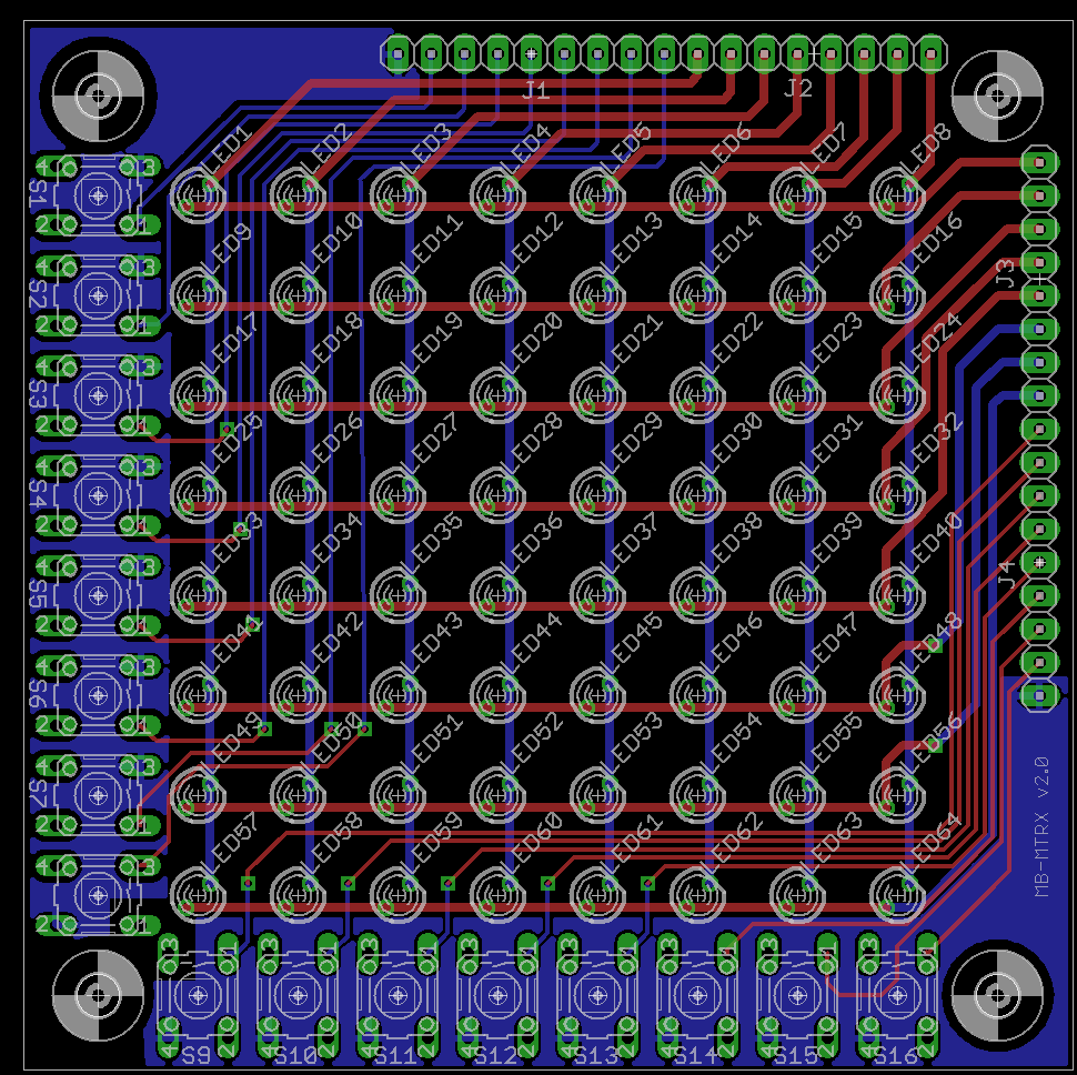
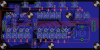
Still need to work on the labeling (pins are swapped for some of the headers, stuff like that), but here is what I'm envisioning it to look like. The board is bigger on all sides, but only by a little and, unlike the old board, is symmetric for the OCD folks :) There are two planes for the buttons that will normally be tied to ground but could be used for a button matrix using a daughter board. The headers are intentionally on the top left to make such a daughterboard smaller (and thus cheaper). Since there is no need for diodes, I removed these off the main board. Folks wanting to do a button matrix could add them onto the daughterboard I think (I don't believe they need to be close to the buttons to work right, although I'm not 100% sure on that). Once I finish this, I'll make the daughterboard next which will basically be a DIN / DOUT board mounted to the back with the idea, as noted previously, being that the board can be part of a chain when using shift registers mounted on control surface boards directly. Fare warning, there will probably be some SMD work involved here since, so far, I have had to use SMD shift register chips for my other control surface components and would prefer to use all the same chips throughout. Plus it should end up saving space (and thus cost) to have the board made.
-
Though so, thanks for clarifying! This means, in my case, I won't need diodes since I won't be using a button matrix.
-
Ah well in that case you'd be all set :) The only catch for you is I will likely have 1 GND pin for each row of buttons (2 total) you will have to account for. I have to do it this way if I want to offer a potential compatible option with a button matrix. I may try to see if I can make that easier via a jumper or something, though. I'm hoping to start work on this tonight so should hopefully have some layouts to share in a few days.
-
Spent some time thinking about this while working on my other boards. I think the size of the LED matrix board would grow in size too much for me to be happy if I tried to cram shift-registers on it. So, instead, my idea is to convert the current LED board design to one that can accommodate the "standard" wiring by default. For folks (such as myself) wanting to do special things, a daughter-board can be used. In my case, I am going to make a daughter-board to house shift registers, resistors, etc. since the rest of my control surface is likely going to use board-mounted shift-registers. For folks wanting to use a button matrix (ala MB-6582), another add-on board could be used. That's probably not something I will be designing myself unless folks already on the bulk order would like it (since originally I was thinking of using a button matrix when I designed the board initially). Everybody wins this way, except for those wanting to do fancy things, as this will increase the costs, but I think is the best route to go to offer the most options. Thoughts?
-
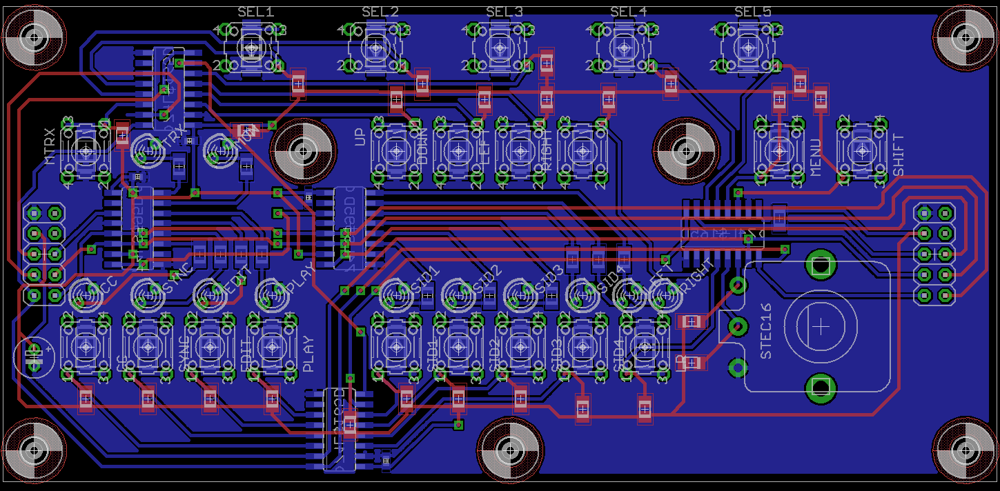
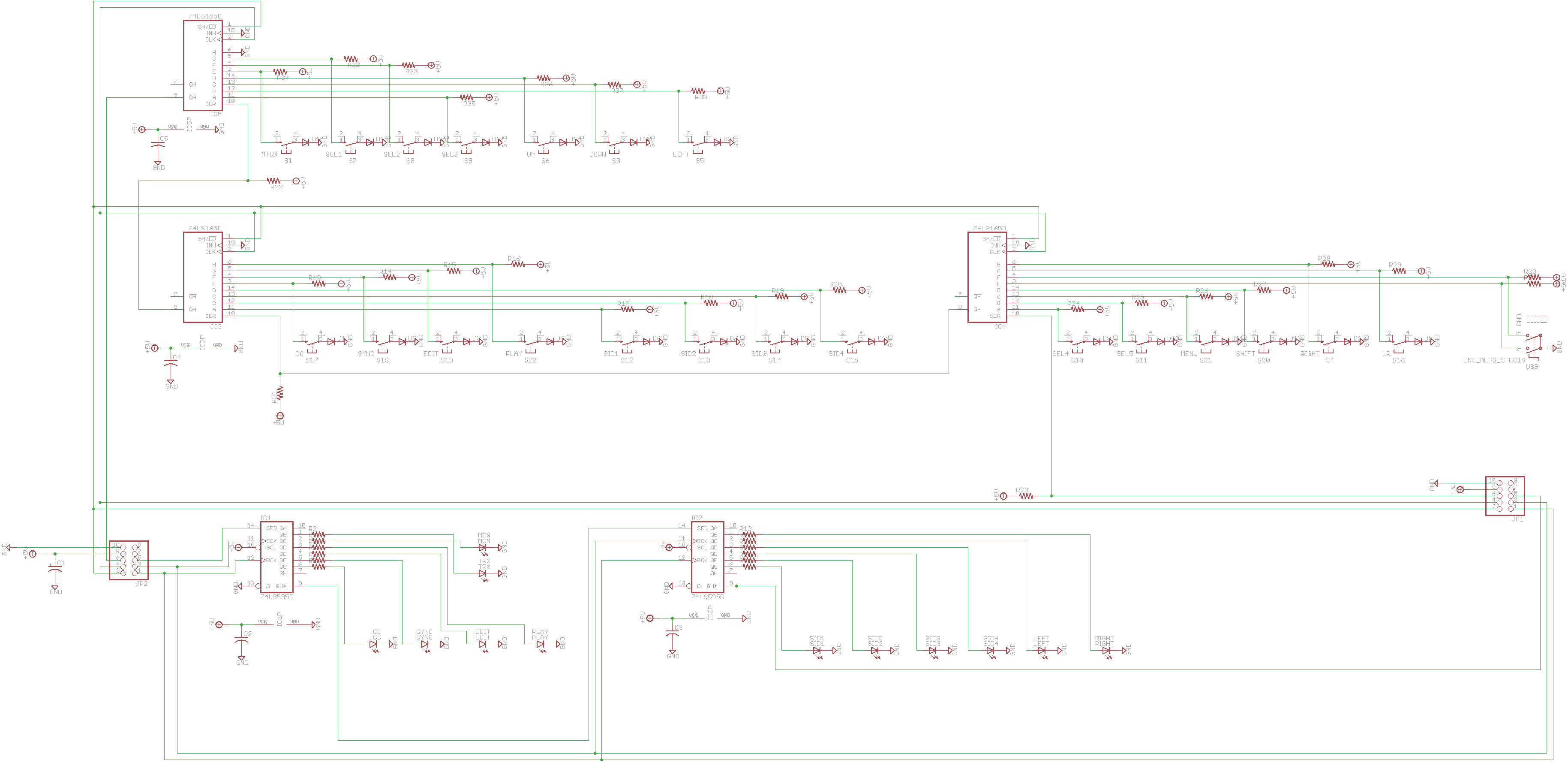
I opted to move away from the MB6582 button-matrix design and, instead, use standard shift-registers mounted on my control surface boards. Less modules, less wires to connect between boards, etc. This is primarily because I am limited in Eagle Standard and can't create a single control surface board (where a button-matrix would certainly make more sense). Thing is, I'm so used to using diodes for buttons but with just using shift-registers, I assume that they are no longer required (but probably don't hurt anything either)? I know the pull-up resistors are required to prevent phantom button presses and things but I assume the diodes are optional? Also, when does an isolation plane make sense? How about a power plane? The bottom plane is for ground but most of the top wires are for power, so I was curious if I should use an isolation plane, or if a power plan would even make sense. I hate wasting copper :) For the curious, I've included the first board I switched over to using on-board SRs. There's quite a few SMD parts on it but I figured that would make the layout easier, which seems to be the case (though I have more vias than I'd like). EDIT: For to ask about grounding unused pins for the input SRs? Yes?
-
Ah thanks! Glad you like it! Not as much MidiBox stuff used on our first album (some here and there) but we use the NES and GameBoy quite a bit.
-
For some reason, jSynthLib isn't working very well on my Winders 7 machine. I can't download patch banks and opening the edit window of a patch ends up causing this weird redraw issue where I can't see most of the window to edit the parameters. I looked at the VSTi options pinned on the MBFM forum but a link is busted on one and the other requires a login. Both appear to be rather old. Actually jSynthLib hasn't been updated in a long time too. So...curious about what people are doing these days to control patches on their MBFM? Or if anyone is having or had a similar issue that I am with jSynthLib on Windows 7?
-
Audio out preference (RCA, 1/4", Mono, Stereo)?
m00dawg replied to m00dawg's topic in Design Concepts
An MB6582 PSU should fit well within Eagle I would think. I'm using Eagle Standard now, but the MB6582 PSU I made I used Eagle Lite for and I'm pretty sure I used light for this one as well, though I haven't built that one yet (and will probably end up modifying it before I do). -
Indeed there's some good stuff working in this track, nice tune! I do love that awesome FM sound!
-
This is all great stuff! Have you thought about putting some of this on the wiki as well?
-
Indeed I've been perusing through the other post on it :) Are the schems available in any form perhaps? Also, what was the wire-width you used for your control surface bits? I think I'm using thicker wire in EagleCAD for my CS modules currently - so far so good but I have a feeling I could be using smaller.
-
I thought the schematics weren't available for sammichSID? I mean, I can just get the CORE and SID schematics and go to town, although I figured if I could find the CORE + 2 SID module that'd be a better place to start. Either way, I think I'm probably going to use my MB-6582 board for a while since it works and I'll have room in my case for it.
-
For what it's worth, I had an issue with my sammichSID that took me a few weeks to track down, including cutting traces on the board, to find the problem. Turns out it was a bad solder joint that looked like a perfectly good one. Wouldn't think it could hurt just reflowing solder around the audio pipeline for the affected SID. In my case, the short was in the Bank Stick section but I can't imagine that affecting this. Just pointing out the fact that it may not be where you think it is.
-
That's not the thing I was looking for exactly, but it's getting somewhat close! I wonder if nILS will kinda provide the schems :) Hah the pics of it on the grass were FTW :)
-
As far as TKs design, yes and no. For the modifications, there are two ideas I have which affect the usability of the board in different ways (though arguably both are still fairly flexible). The LED wiring will generally remain unchanged because the "standard" MB-SID wiring layout still uses a matrix so this is really only for the behavior of the buttons. 1. Put the shift registers on the board itself such that you only have to connect CORE J8 and J9 to the board. It will have headers to go from the CORE to the additional modules in your control surface. In other words, with this option, there are no DIN/DOUT boards as those have been moved to the various control surface boards. Pros: No wasted space for DIN/DOUT modules in your enclosure and there can be fewer wires connecting the other parts of your control surface together Cons: I haven't tried adding shift registers to the matrix board, but it will likely make it at least a little bigger. Firmware modification may be necessary, but only to define which I/O pins go to where so those should be easy. 2. Assume DIN/DOUT boards will be used external to the LED Matrix and provide headers for these solutions. Pros: Will work with TKs wire outputs and is otherwise very flexible. A jumper could be used to tie the buttons to GND for a standard solution. Otherwise one could use those pins to wire up the buttons in a matrix (with the help of some addition wire off-board - I think). Cons: Won't work as a drop in to the MB-6582 board after these changes are made and will otherwise require DIN/DOUT modules to be used (or similar) Still playing around with the idea as a whole so, at the moment, I haven't done anything to the LED matrix board just yet. I have thought about "both" as an idea. So having option 2 but making a board that you connect to it using the same header positions that would then have the shift register stuff for folks that don't want to use separate DIN/DOUT boards. That won't exactly be cheap but is still a very feasible solution, I think, and keeps the LED matrix board itself smaller. That said, the beauty of the above board shop is that the price includes 3 boards, so costs aren't really too bad if we have as few as 3 people interested. To do medium runs (say 20), costs go down quite a bit at that point. That makes any of these boards designs feasible for what people want to ultimately do.
-
Yeah that's what that extra box at the bottom is - that's the plastic bit that juts out from the audio jacks I've found (which are similar to the ones Wilba used on the MB6582, Sammich, etc.). I was going to mount the jacks on the opposite side of the headers so that I only have to worry about the pins jutting out on the short side. Since then, though, I've gone back and forth on moving to a mono solution which will reduce the pin count by a small amount. Due to way I'm now envisioning wiring it all up, I'll likely also use 90 degree pin headers and mount them off the edge of the board so hopefully I can further avoid any gotchas on the jack length.
-
So I've been thinking about making things simpler for my own CS design and perhaps moving to a system where I mount shift-registers directly on the control surface modules (including the 8x8 LED matrix). This would do away with the requirement to use a transistor sink (ala MB6582) but also means that folks wanting to use the LED matrix in a standard MB-6582 might be stuck. Curious what people currently on this bulk order are interested in doing? I could put the SRs on the board itself, or just go to a standard pinout which one could use (with an extra board or clever wiring) on the MB6582 though I personally favor SRs on the board because it means the wiring of all my CS modules will be much simpler (or so it that idea). Still pondering things so I haven't made up my mind on it yet but wanted to keep folks in the loop! The good news is that the board house I was going to use is still quite inexpensive for folks that might want to use the old design if I do change things around.
-
TwinSID is close but it's a full featured solution it would seem, much like sammichSID. The board I saw was basically a CORE plus 2 SID modules in one neat package (I think it contained a bankstick too). It was nice because, though being modular, it took up less room and I wanted to see if I could use that for the basis of what I wanted to do. MB6582 will work just fine, although it's easier for my to wrap my head around a standard DIN/DOUT setup instead of the transistor sink. The wiring of my control surface has also been complicated, but I think I could simplify that by using my own wiring matrix (originally I was going to use the exact same connections but that doesn't really fit well with my CS design). I like the idea of getting rid of things I don't need (like space for MIDI jacks, which will be panel mount for my design) although a modular design would probably, at best, be the same size as the MB6582 board (and probably more). Just a thought I had though.