m00dawg
-
Posts
1,404 -
Joined
-
Last visited
-
Days Won
16
Content Type
Profiles
Forums
Blogs
Gallery
Everything posted by m00dawg
-
Hah that's a VERY good idea! I dunno how much room I'll have but yeah, I'll give that a go. Dunno why that didn't cross my mind. Flying Panther's design was getting close to that idea. I didn't end up using that just for keeping continuity with the other sections and I kept crossing into the LCD bezel for the parts, doh. Now that I have that figured out perhaps I can be more adventurous. I'll give that a go perhaps tonight or tomorrow. Thanks for the cool idea!
-
Maintained enough as it needs to be; it supports all the SID v2 features. I have had weird behavior when running it along-side a DAW though so I don't use it for realtime changes because of that. Otherwise, it does the job, perhaps with less finesse than it could, but it works and it's free :)
-
Actually, I liked the idea of the supports quite a bit, but I didn't know of a good way to apply it. I know what you're talking about, though, because I have seen solutions like that before. The JB-Weld should be easy enough, and I was going to use it for the board stand-offs in the chassis as well anyway. For the lettering, I thought about putting the text above, but the screws would actually go through the 2nd row of text (at least on the bottom row of knobs) so I need to find a way to move two rows around. I thought about doing some crazy things but never found something I liked. I may add the center screws on the sides of the panels back in since they don't get in the way and help split up the sections naturally without using lines. I did find out that I can have my line-art if I move the text from being above the buttons and LEDs to below, but I haven't found a look I like and it may put some of the text close too the knobs. Something to try, but at least I (hopefully) won't have to move many things around at this point. Maybe I missed it but I wish FrontPanel Express and Eagle had measuring tools. If I knew the distance, say, between the screws and various components, it would have been wildly easier.
-
If it were me, I would likely steer clear of the hard-drive PSU. You don't know it's switching frequency (unless you're lucky and they put it on the label along with the wattage) and many of them use annoying connectors that may make finding a replacement difficult. Instead, I would have a look at thread as it is one of the most in-depth PSU discussions I have found on the forums, and it's fairly recent. It does discuss some switching PSU options as well if a switcher is what you want to go with, though there are quite a few linear options discussed as well. It's lengthy, but a very good read and may help you decide what to do.
-
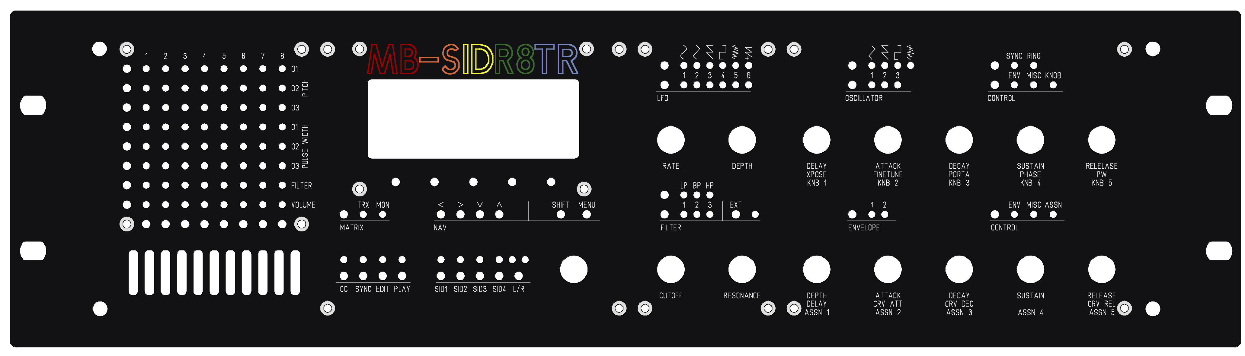
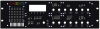
Here it is! All my CS boards have been measured and appear to line up as well, so I don't expect to change things too much unless I run into a routing issue (and, man, as hard as the LCD area was for me, I'd rather just have a 4 layer board printed than have to go back to that :P). This one only shows the screw-holes in the corners. While I like Flying Panther's idea of adding supports, I decided the JB-Weld probably wouldn't be as bad since if it fails, it just means the board will flex a bit more. It also allows me to put mounts in odd places without much of an issue (as long as I can route around it). I would have gone without except I cannot figure out how to avoid cutting off the text under some of the knobs. The other issue is the engraved lines I used in previous iterations. The filter mode text would get cut through. As a result, I may play around with different styles (such as moving the text below the LEDs, though I may have to get rid of some of the line-art to do that). It's coming along, though and now that I have everything measured, hopefully any changes are just going to be cosmetic (colors, line art, etc.). EDIT: I forgot to mention, the screws around the LCD are for reference as these are (sort of) where the LCD would screw into the control surface board. I'm leaving them there for now just in case, but they won't be in the final design. MB-SIDR8TR.zip
-
I had to end up increasing the spacing slightly as it was running into the button pads. I also moved the LCD hole up a bit and am toying with moving the knobs down and making them equidistant to the LEDs and buttons. Since I am planning on using flat-head screws, I don't think the buttons being close to the screw-holes will be much of an issue, but moving the knobs down does move the text under them down beyond the mid-point which means I won't be able to put a line there. Will post an update once I finish all the measuring and hopefully decide on the final positions of the knobs. I'm pretty close to having everything properly measured so once I do that, the panel hopefully won't need much modification.
-
Yep agreed! Trying to figure out if the LEDs above the CC, ... and SID sections are too far/close? Dunno. So far all the boards fit the measurements but I haven't started routing wires yet. I realized that having the components positioned perfectly for all the boards first is a very very good idea :) Still mulling over adding the extra screws as well. The MB6582 CS board seems like it has some flex to it, even with just small bit of pressure, when holding it from the sides. So I think the extra screws may be needed. I really didn't want to mess with JB-Weld though. Humm...
-
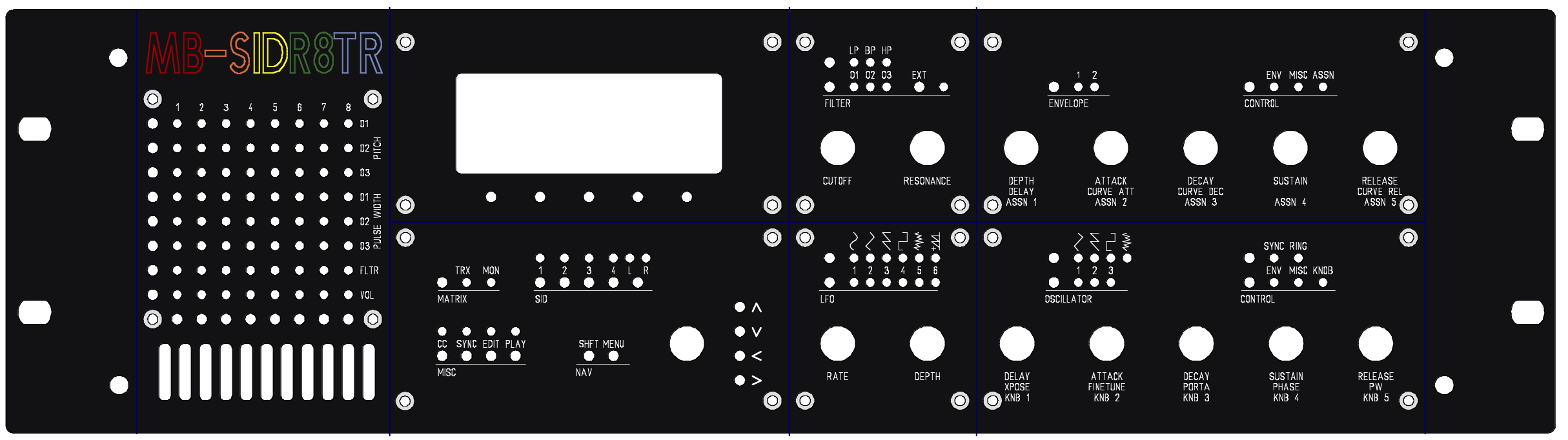
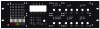
Here's another update! This one is quite a bit different since again messed up the LCD area (ARGH!). It ended up being a good thing because I realized I could use fewer boards without running into the limitations of the non-profit version of Eagle. Turns out 100x160mm is for actual parts. The board itself as well as the mounting holes (and even wires) can surpass this which meant that I had just enough room to make boards as large as the height I needed. I also diddled with the center section a bit and so far I like the layout much better. I currently have screws just on the corners but I tried adding a few more screws along the centerlines. I think I may opt to use JB-Weld there because I really like having those lines on the board from previous designs. Plus, the screws in the center of the Envilator board clobber the knob text. I just didn't want to use JB-Weld as the sole means of keeping the board mounted (didn't want stuff falling onto the synth boards if I ended up sucking at using it. I'd rather just keep the screws on the corners but thought the boards might flex and make the control surface spongy. Anyone have any thoughts there?
-
For Windows, ASID XP is basically what you got, and unfortunately, it kinda sucks. TK patched SIDPlay for OS X. post has more information. You could likely ask TK very nicely for the source, although he is using MIDI Patchbay, so I am not sure what you would need to do on the Windows side (MIDI Yoke perhaps?). There's no better solution for Windows I am aware of today other than ASID XP. I don't think it was a MidiBox project, but there is a project out there that lets you load songs onto an EEPROM and play it. Can't remember where I found that project though.
-
Sweet!
-
I think it's worthwhile to test it that way; I just dunno if I would leave it. Could be your power supply but it's odd you're getting low numbers from the regulators. If you had another supply, I would definitely try it. Before you go and buy another PSU though, I'd try to get another opinion (as in, other than mine :) )
-
Hmm something sounds amiss there then, perhaps somewhere in the SID section. Using a 12V supply and 8580/6582 SIDs, you should now need to bridge JBP (in fact looking at the build doc it says NOT to do that - the jumpers for JP should be in the horizontal position). That said, those voltages look good otherwise. I think there's still some sort of grounding issue afoot.
-
Finished adding through-hole option for the diodes. Either is now an option. The through-hole option should accommodate diodes in a D-7.5 package. I would still recommend the SMD option but it's nice to have choices :) I am still debating on whether or use a separate pins for the tactile switches or share the two LED pins. I tried to have it both ways but I think that could make things a bit cramped so I'm going for an either/or here most likely. I'm leaning towards adding the dedicated pins back just so there were more options since one can combine the outputs using other means if the bottons and LEDs are sharing the same pins (on the MB-6582, they all share JDB). Updates are on the MB-SIDR8TR wiki page.
-
9.8V on the 12V is likely just due to the voltage drop over the bridge rectifier. You can verify that by looking at the voltage from the DC in jack and then after the rectifier. I run a 12VDC supply on my Sammich so it's probably ok, though 11.5V is a little low. It's better to be slightly over than under (though the more over you are, the more heat those regulators will generate). 8.2V seems low after 7809. I'm not sure how low you can go, but I wouldn't like to go under 8.5V myself (some other folks may want to chime in here about that). I wonder if there is something going on with GND. I would double-check for any shorts for anything that's close to a ground pin, particularly around the regulator section. I would pull your chips for now as well. I wouldn't stuff them again until you fix the voltage issue. In fact, I would re-check your voltages with no chips if you haven't done so yet.
-
Something is definitely off if you're not reading correct voltages out of the voltage regulators. Those should be very close to the rated voltage of their outputs, so try checking the outputs of those and work your way forward. If you don't get the proper voltage there, start working backwards and check for shorts. Typically, the regulators either output proper voltage, or close to none at all so if you're reading incorrect voltages there, something is amiss. Keep in mind, too, that you need about 2V above the rated voltage of normal 78xx regulators. So for a 7809, you need 11V. 10.5V may be too little. Also, knowing if you're using AC or DC may be helpful as 12VAC would give you about 14VDC unregulated after the rectifier, depending on what your actual input voltage from the wall is. You mentioned that your power supply is "set at" 12VDC. That sounds to me like a switch-mode. I don't know of any wall-warts that allow configuring out the output that are not switch-mode. That, however, is probably not a factor for getting proper voltages as long as the wall-wart is rated correctly (I think up to 500mA is recommended for the Sammich, but I would check the docs on that one).
-
Glad to hear you found it! Mine plight took a few weeks (and ended up being a bad solder joint though I had to cut tracks to actually find it).
-
Oooh yeah good call there. One thing about the grey is that it might look sort of like my blue MB-6582 panel. I used the light blue for the lines and dark blue for the panel itself. Odd thing is in certain like, it looks reversed which was a cool look! The one thing I didn't like about the blue was that it didn't really fit with the colors of the logo. I tried to get the colors close to that of the C64 logo. I'll try the other blue and see how that may look as well as try the border around the whole thing see how that looks. I can actually have that serve a function and put the border where the actual chassis border is (hopefully that will help me pay attention to those from now on :) )
-
Ah hey that's a cool idea! I was trying to figure out how to move the knob up without making it look vertically weird due to the other knobs and stuff and I hadn't thought of doing it the way you did. You caught my unaligned vents. I do plan on fixing them just didn't get around to it yet. ;) As far as the lines, I have tried it both with and without. I kinda like them myself. I don't like that they run off the edges - I thought about putting a border around everything and maybe switch from a blue to a grey. On my MB-6582 panel, the blue lines looked really cool so I kinda ended up being fond of them. Not having lines is probably cheaper, though. I'm hoping to finish measurements a bit quicker this time since I am going to lay all the boards out first, check to clearance on the chassis and then do the wiring. The only ones I'm worried about would be the LFO, Filter, and LCD sections. The other ones are pretty easy (I was even able to do the ENV board using a single layer). Anyways thanks a bunch for the feedback!
-
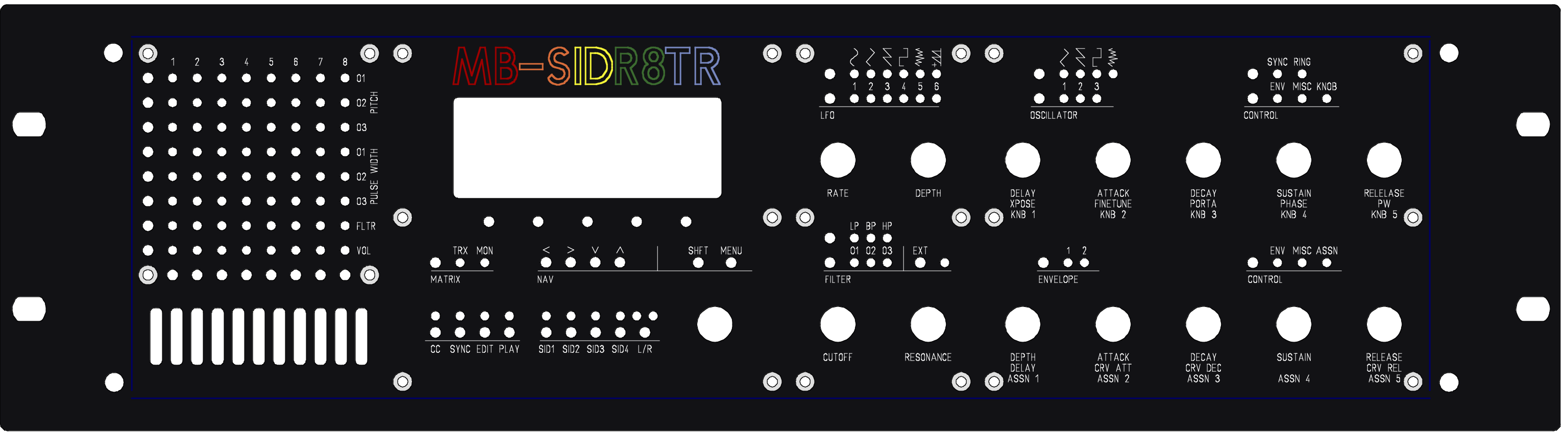
Here's what I came up with. Not perfect, but better! So far, everything seems like it fits but I'm still comparing my board designs to the panel, paying more careful attention to the LCD panel since that is what set everything in motion with having to redesign it in the first place.
-
You should be able to extend the sammichSID, yes. You can always just use the base board and make your own control surface by chaining your ins and outs. It looks there is also extra headers on the top board too, giving you some nice potential options. Keep in mind that buttons for the current iteration of the above board are sharing 2 pins with the LEDs as I was going to use the MB-6582. Both the LEDs and buttons share JD8 so I was able to save some space. I am thinking of going back to the old way, however, so individuals had some options since one can always connect the buttons to the JD8 header using some other means. Either way, the design assumes that a button and LED matrix are used (ala MB-6582) so I would check here for some info on that. Wilba described how it works in greater detail in a forum post but I haven't found it yet to give you a link (it's there though, I looked at it last week :) ). EDIT: Doh I forgot to mention while I had the floor :) I am planning on offering both SMD pads *AND* through holes for the diodes. That the outline for the 6x6 tactile switches is elongated in Eagle such that using through holes, while close, should be fine in many cases. I think I'm still going to bust out some hard-core SMD action, those wanting their own board can now use either/or. Thanks to SmashTV for providing the info and most excellent suggestion! The one caveat is that I need to use octagonal pads for the through hole diodes so they will take a bit more effort to solder (not much). I could use elongated pads but they would make the board slightly bigger and I would put some components closer than I would prefer. I'm still working out some of the details but will post an update here and on the wiki once I have that finished. EDIT 2: (sorry I just drank a tall glass of Promised Land Dairy Chocolate Milk so I'm kinda wired :) also welcome to the forums, Stormcaller!
-
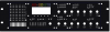
So I've redesigned my front panel probably 5 times now. I finally have space figured out for the LCD panel, and even had some extra space to work with. Trouble is things don't look quite right. The section below the LCD panel looks either jumbled or bare, depending on how I orient things, and I would love a second opinion on if the knobs on the right section may be too close. I was hoping someone might have some thoughts? Maybe a fresh pair of eyes on it will help. The things I don't want to change are the right-hand section, which means I can't really change the width around the LCD, say to make room for the menu knob. The top and bottom-most screws also can't move much as these are as far out as I can go and still fit boards in the chassis. Finally, I'm limited to 100 x 160 mm for the max board size in Eagle (which is why the filter and LFO sections are on their own). Things would be much easier if I didn't have those limitations but I gots what I gots :) For those that saw my looks like I'm going with a 4x20 as it ended up fitting better than the 2x20 (Wilba was dead on there) and I two that may work well (a yellow or green background or a yellow on black background). By the way, props again to Wilba - making control surfaces can be tedious and error prone (but very very rewarding). EDIT: Dum dee dum...would help to include the actual panel in the post, eh? :)
-
Well, I didn't actually say RTFM, but... :) Actually one thing I'm not sure of is if 2x24 displays require some modification. I think the actual setting is an integer (1 = 2x20, 2 = 4x20, etc.) but, again, I haven't looked (which means I haven't RTFM'd either :P). Ooh and actually I did gloss over a bit when I said it's a simple change. Making the LCD work is, but you also need to adding the extra buttons for under the LCD. That's just a matter of editing a table in the code though, so it's not a huge deal.
-
Well, after moving things around, now it's like I have too much room :) I think a 2x40 will fit on my CS, but I'm bumping into the limitations of Eagle Standard and it makes things pretty cramped around the LCD. I was thinking about a 2x24 instead, since that gives me one extra button. The selection at CrystalFontz for the 2x24 and 2x40 isn't that immense - no inverted options for instance. There are a few inverted options for the 4x20 though the 2x20's have the most color selections by far. I'm trying to weigh the pros and cons of a 4x20 or a 2x20 :) So far the 2x20 will fit better for the gap between the front panel and CS boards I was planning for, gives me almost too much room, and gives me the color choices I want. The 4x20 gives me a compromise in color, the cool graphics (namely the progress bar thing, though useless, it looks so cool :) ), but a vertically asymmetric control surface that may end up bugging me; and the bezel is too tall to fit for the gap I was planning. So far I have both options. Not sure which one I'm going to end up going with (leaning towards the 2x20 though). For the inverted LCD screens (such as green text on black), is there anything I need to know? I assume it just hooks like up a standard LCD? Thanks for all the help and guidance all!
-
So I found a few options using the male/female spacers (thanks again, Nebula!) Here are some 9mm spacers from Mouser. Trouble is, it's out of stock with an estimated 9 week restocking time. Ouch. Here are spacers with a US length of 11/32" which is about 8.73mm. The bourns encoders I am using are around 8.27mm from the base to that front metal bubble thing. So this sounds like it could do the trick as that gives me 10.75 for a 2mm panel or 11.25 for a 2.5mm panel, both of which are less then the 11.5mm I calculated earlier, but not so much that it would be ridiculous (I don't think). As much as I hate to say it, if the US standoffs are in stock, the US measurement system may have, unfortunately, won this round :) (Yes, I live in the US, but I think inches and feet are stupid). EDIT: After I slept on it, I realized I needed to measure the LCD panel. Sure enough the 4x20 I have requires about 8.7mm of space, so that's making things a bit close...hmmm... EDIT2: LCD should be ok since the actual distance is the bezel minus the board thinkness (since it is mounted behind the board). Last I measured it was around 8.2mm I believe. Close, but not a problem I suspect.
-
Woo that design looks very very cool! Sounds like someone needs to finish it :) Your design is more what I wanted to go with but the vertical room is more of a problem than I realized. I originally was planning on using screw mounts through the front-panel but I could likely get clever by using JBWeld (so I can put the screws wherever I can). I also have the problem of being limited to 100x160 per board (I have the non-commercial EagleCAD license). I'm trying to figure out the best way to cram everything together without it being cramped or weird looking :) Haven't figured it out yet, though I think the 2x20 seems to be the likely candidate. I don't want to scrap all my previous work but I think I am going to try various other front panel designs to see if I find one I like better than can use either the 4x20 or 2x40 as both look cool and aren't so standard and vanilla as a 2x20 :)