m00dawg
-
Posts
1,404 -
Joined
-
Last visited
-
Days Won
16
Content Type
Profiles
Forums
Blogs
Gallery
Everything posted by m00dawg
-
w00t thanks Wilba!
-
Will the schematics be posted online? I am trying to be a bit more diligent about testing as I go and really want to make sure I get continuity on the tracks for the SMD devices. Since some of them run under the chips, it would be easier if I could have a PDF I can zoom down into (much like the MB6582 one). If no, I can make due but thought I'd ask :)
-
can replacing components give better sound quality
m00dawg replied to Echopraxia's topic in MIDIbox FM
Could play with some filtering caps on the audio pipeline, but if the noise in the SID or OPL3 is bothering, you can try to filter it in post. I haven't noticed any major issues with noise on my SIDs (don't have my FM synth built yet). I have 6582's though and they are a good deal better than my single 6581. Just part of the draw and intrigue of using vintage sound chips. -
I don't think you need the latchup on the regulated DC outs from the Mean-Well? I doubt they hurt anything though but the Mean-Well has safety features on it as well. As far as the filtering caps, yes they can compliment each other though you may want to look at tantalums in replacement or addition to ceramics. They tend to handle HF noise a better. Some people on the forums hate them, but as long as you pick out a properly rated cap I doubt there is anything to be concerned with. They have lower tolerances to voltage than electrolytics and are a bit more expensive but likely worth it if you really want to attenuate HF noise. Leaving caps on the SID side is probably not going to protect it but may help give you more stable power or at least won't hurt anything. The .1uF is likely more for the regulator. Speaking of, be sure to check the datasheets for the regulator you are using since they often have very good information about capacitor choice and location.
-
Thanks TK, that was very informative! Excited to see what the future holds for the new platform!
-
Sounds promising! Curious as to why the STM32 is being replaced? Just mild curiosity :) I don't have any STM32 projects at this point or anything.
-
Ah yeah that's what I suspected. Oh well.
-
Hmm I'm getting a broken link? Tried to search the forums for it but didn't come up with much about a new dev board.
-
 *WOW*
*WOW* -
Ah well you can drop those in a sammichSID for now :) I too have a few SIDs I hoarded for a rainy day :)
-
I believe so yeah but I can't remember where I read that :) I suspect it may be a ways before we'll see that solution though. It's not stopping me from moving forward with my own v2 SID design anyway. I recall Wilba mentioning that it may be possible to add the STM32 CORE as an add-on to the MB-6582 so as long as one has space of it in their chassis (or uses some external solution) we could be in business without a lot of modifications? Too soon to say and I'll admit I actually know comparatively little about the MBSID v3 project :)
-
I thought there was a MBSID v3 in the works? TK was playing around with overclocking the SIDs to get around the ADSR bug last I recall?
-
Hi Shiftone! I don't know the answer to the status of V3 but you may find more in the SVN repository (details are on the wiki I believe) since that is where the V3 code would live. I would bet that, just like V2, V3 will allow both modular and unified designs. There is no reason not to and doing so allows for the most flexibility of all types of designs.
-
I only know in the context of the MB-SID but I assume the other projects are the same - they allow you to select items on the screen, typically on the second row of a 2xYY LCD screen. See this for an example. The LCD examples in the link illustrate what I'm talking about. Typically you would have buttons along the bottom so you can pick the item being displayed. So on the 2x20 example, the left most button would control the OSC, the second the WAV type, etc. It's very handy for when you want to change parameters and do not have a dedicated control item to do it, among other things.
-
If you're in the states, I would just buy the kit from SmashTV. Yes, it's a bit expensive but all those components adds up so you may end up paying about the same anyway, but have to go through all the hassle of buying the parts that all come with the kit. The only things the kit lacks are machine pin strips if you want to replace the filter caps or LEDs (to adjust the brightness to where you like it). I also bought some sockets for my SIDs so I can double-stack the sockets and thereby avoid bending the pins on the SIDs when having to install and remove them while testing. I've bought two kits from SmashTV this way have have been happy. If you already bought the boards, I would ask him about just the parts (can't hurt) to see if you can get them separately. That's for the baseboard. There is no kit for the control-surface, but those parts can be easily had. I forgot the model numbers off-hand but they are on Wilba's wiki page for the MB-6582 control surface parts list. I know that wasn't a "yes" answer, but hope that helps :)
-
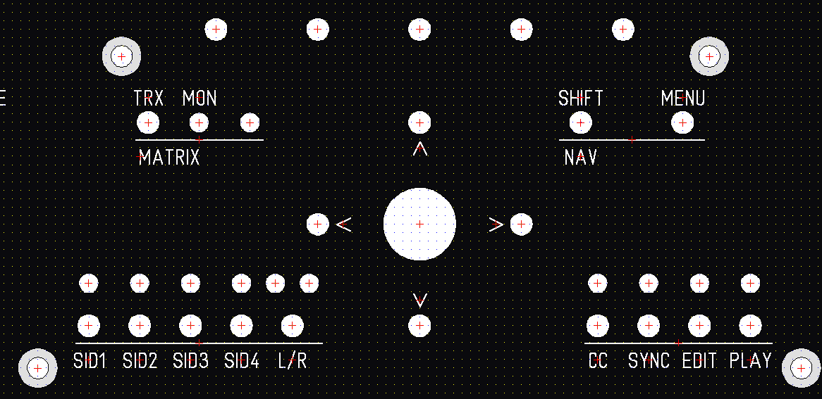
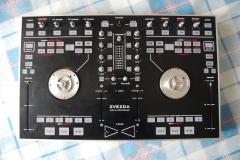
So I really liked the plus pattern around the knob, although it does indeed get in the way. Not so much for the up/down but more for the left/right. Given the space constraints I think I'll have to stick with the original design (which puts the arrows on their own row). Unlike the MB-6582, I opted to go with an up/down/left/right arrangement. Being a lefty, I think I would actually prefer them to be to the right of the knob, but I am probably going to leave them as is (to the left) since the synth will sit on my left and I will be using only one hand to control things most of the time. As far as the panel goes, I think the only thing left to do is decide on is where to put the blind holes (if I want them on the corners or not - seems like almost a no-brainer to use them for the middle screw-mounts). I think I'm going to start routing wires on the actual boards first though to make sure everything fits. Since some of the screws will be hidden, I can put them in odd locations without much worry. The blind hole idea is fantastic, so thanks again, Altitude! I think at this point it's on to the next step (routing the wires on the boards).
-
Ah yeah, sorry to be more specific, I meant the corner screws of the various CS modules. So like the corner screws around the LED matrix, etc. I was going to keep the panel to chassis mount screws yeah.
-
Oh haha duh, I was looking at the wrong thing when I searched for "set screw" initially. So it's basically just threads with no head. I guess one just screws them in snug and then just screws in the female header onto it? Pretty clever solution! In my case, that works out well because I was going to use female/male standoffs (so I can a fix the CS boards using a nut on the bottom). Are set screws something I can do for the entire panel then or should I keep the standard corner screws? I sort of like the corner screws actually, but I might like to hide them if I can make room for the engraved lines that break up the different sections (like I had in my previous designs). Thank you very much for the help! Learned quite a bit from this thread, so thanks everyone!
-
@nebula Hmm good point there. I haven't found much need for the directional buttons honestly on the Sammich. My MB-6582 was only working well for a very short period of time :) So I never got to mess with it much. I do like the look of the arrows around the button better, but you do have a point. I will try doing some tests with my knob caps to see how things go since I was worried that they might be too close (just didn't have time to test it yet). The nice thing is the panel is basically complete so moving things around is really just for experimentation - I have a panel now that I will likely be able to go with (assuming I can route the wires on my CS boards for the front panel's configuration). @Altitude Can you elaborate a bit on the set screw idea? Do you just lightly tap those in or?
-
Yeah it's 2mm mostly because it's the default. Do you think it would flex that much in a rack though? Either way, cutting the recess for the LCD is a pretty clever idea! If I ended up getting anything thicker than 2mm, I can just offset the recess to make sure I don't run out of room. Not sure what to put for specs for a blind hole though. I assume I would also have to be pretty accurate on measuring the necessary screw depth for that? I could go with an un-threaded hole though and use that cavity to better fill in with JB-Weld though?
-
Hmm something odd is afoot and I don't have a clear answer for what it is. The typical "check your solder joints and wiring" suggestion comes to mind. More often than not I've seen it be a bad solder joint causing weirdness (I've had weirdness on my own PSU designs caused by that) so even though it's a typical response, it's still good advice. Are you sure you have the bridge rectifier connected correctly?
-
Dragging down by how much? That's not very specific and a number would be helpful there. Be sure you're checking the voltage against the 5V GND and not the GND connected to the 7809 (since that's actually 5V). Also, not to be the grammar fanatic, but grouping your thoughts into paragraphs and proper sentence punctuation will make your responses much easier to read and understand. That will likely get more people to help you out because I actually had somewhat of a hard time reading your initial response. Anyways hope that helps!
-
Yes, you can just use one 7809 and provide 9VDC if you only have 6582/8580 SIDs. In that case, the middle pin of the 7809 would just be tied to ground. Since it's powering all your SIDs, you may need to put a heatsink on it. Based upon your explanation, I am not sure why you are not getting 14VDC unfortunately :/
-
Took a bit of work but here's a rough draft orienting the navigation arrows around the menu knob. I haven't checked to make sure all the components fit well but I think I have at least cleared the encoder base (it's rather large) so I think it should be good. It feels a bit cluttered mostly because the SID L/R makes the bottom row unbalanced, but I'm not sure if that can be fixed easily.
-
I think the Audio Kontrol uses the same DACs that are found in the Audio DJ line-up of products. If so, I would continue to use that for your phones as my Audio 4 sounds amazing. I think the Audio Kontrol has a hardware mixer as well? My Audio 4 DJ does not and so if I want to monitor an input, it's subject to small delay. As a result, I don't really use it for recording, though it's a great tool for my DJing.