m00dawg
-
Posts
1,404 -
Joined
-
Last visited
-
Days Won
16
Content Type
Profiles
Forums
Blogs
Gallery
Everything posted by m00dawg
-
The OSX version has stuff in weird places it would seem. I was able to find the mixer by opening the info window (Command-I) and it has an option to mute the the 3 voices. I didn't have an option for digital in but I tested that by busting out some Turbo Outrun action. Seems to work like a champ! Also found out Jeroen Tel uses samples for the bassline too. Very clever!
-
Decided to bust this out again recently so I could jam to some SID tunes while working. On thing I was curious about, and it's sort of a daft request, but since it is not possible to play digital samples directly from the MB-SID, the next best thing would be to mute all but the digital audio on the regular computer out. That way, the normal SID channels are played via MIDI to the MB-SID but the digital samples from the computer. Sounds sort of weird but this way I'm not missing anything when jamming to SIDs since I can mix the MB-SID and computer out together. Anyone have any thoughts about how to do that? I didn't see a way in SIDPLAY to mute channels?
-
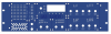
Ah you busted me on not fixing some of the text objects. I am using a .100" grid most of the time but need a .05" to fix the text and I just forgot to do that after moving stuff around. I actually thought the filter/lfo location looked kinda cool myself :) I intentionally moved the screw-holes down for the logo actually. In terms of symmetry, at least when looking at that section (the middle section with the LCD), I thought it looked pretty neat. The section I don't like is the matrix / SID selection sections. It's been when I moved the screws further apart on the matrix to match stuff but they look a bit weird if you look at the top screw-holes over the bottom. Good idea on the phones thing, though may have to play around with that anyway. I sit on the right of the synths so I would want the headphone jack to be on the right. Previous attempts and switching the matrix and osc/env sections did not go so well but I think I have the basic layout of the sections done such that it may not be as much of an issue. Yes, depending on how you look at it, the OSC selection is flipped. Originally, I tried to make the most important thing on the top row. So in this case, for me, sync/ring is not as important as the OSC numbers. For the LFO, the type is more important than the number - same for the filter. I sort of see what you mean now when looking at all the sections. I dunno if that would bother me directly but yeah will probably look a bit strange. I tried using single rows of buttons but I started running low on space without things getting really cramped - I can't make the matrix/selector sections much more narrow - not enough to likely fit the additional space the LFO/Filter's needed without really breaking symmetry. I tried various ways to do that but didn't come up with anything better than using two rows - though I'm certainly open to suggestion there. Yes I'm a soutpaw :)
-
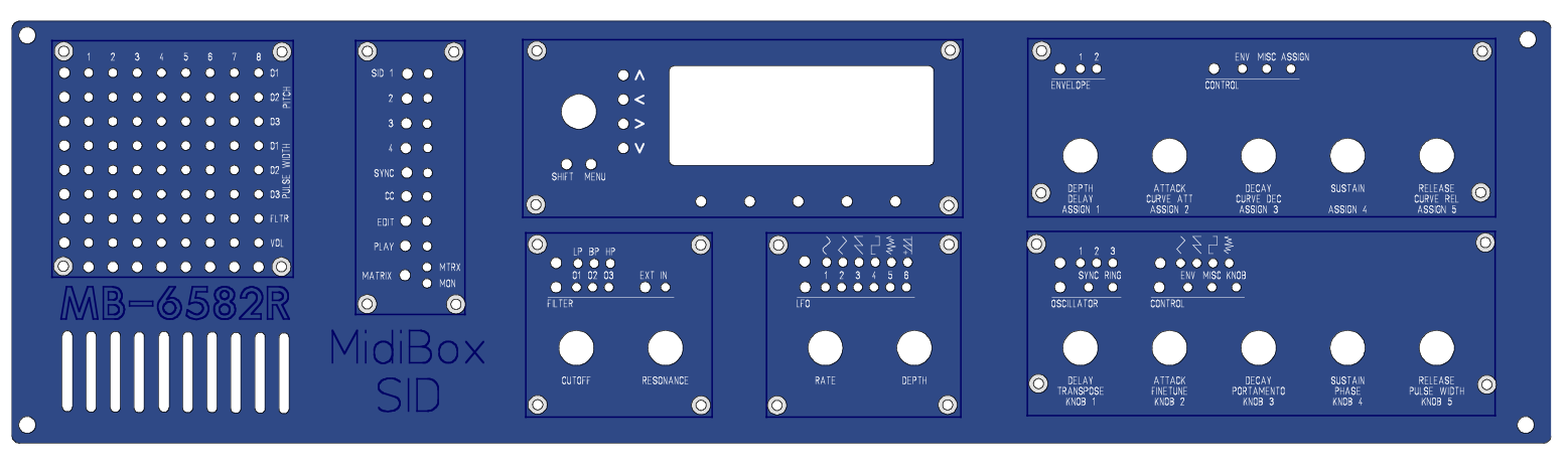
Rackmount chassis arrived from Jameco today so I updated the panel with the screw holes. I don't have one of those fancy digital spanner things yet but eyeballing it I was able to get things pretty close. Likely close enough for things to work but I will have to remeasure it before dropping $200 on a panel :) Anyways I made a buncha changes so thought I'd share. mb6582-R.zip
-
Hah I forgot about simulator, thanks nILS! Super helpful as always! By removing the inverter, I noticed that the output level drops from 3.49V to about 1.5V. I did not notice any audible drop between the CPU pins versus the RF out though? I think I read online that using the hex inverter was sort of a cheap way to amplify the signal, but that doesn't make much sense to me :) Either way, I'll keep playing around with the simulator. I forgot about the gem! There are some audioheads on the NESdev forums so I may give them a shout to see what they think.
-
Aha! I found this: http://nesdev.parodius.com/NESAudio.gif (included in post). It has similarities to the SID audio stuff but is generally more complicated. I was able to get some knowledge from forum post. Specifically, the this link (thanks nILS!). But there's still some questions raised. For one, if I'm having a problem with noise, should I even look at reimplementing the NES audio stuff directly if the current implementation seems noisy? I read that the 74HCU04 is really a hex-inverter but I am not sure what purpose that would serve. One schematic I found online (here) just uses a few resistors, but that seems too plain - don't you need at least one cap for protecting the chip and such?
-
Is the SID audio pipeline generally a standard way of doing things? In other words, would a similar design work on, say, the audio output pins of the 2A03 (NES)? The reason I ask is that I have found that the audio-out of the NES is *noisy* . The regular audio out has a discernible buzz. I thought it was due to a bad power brick but I have tried using batteries too and, while it's better, it's not amazing. I suspect my RF modulator section needs some love (such as new caps) but I can only get to the big cap which I have already replaced. The others are covered by the RF shield and I don't have the tools to desolder that thing. It could be something else too since I have grabbed the audio from one of the last resistors before the RF section and it still had some buzz to it. I noticed that I tapping the audio pins off the 2A03 was orders of magnitude quieter. The tri/noise/dpcm pin does still have some buzz. I suspect that might be a grounding thing? The square wave pin sounds immaculate. To make sure I don't damage the chip, I was wanting to make a proper audio out right off the 2A03's pins as was as to capture audio in from the cartridges separately. That will not only help for mastering but, I'm hoping, should greatly reduce noise. The audio in from the carts is kinda of optional. I was thinking about doing that to use the PowerPak for it's emulation of the extra sound chips (such as the VRC6). It seems to sound better than over software emulation. I suspect because it sounds grungy-er and generally more 8-bit. Anyways, after reading online, I found a brief mention of how to output from the 2A03 that had some similarities the audio out of the SID (from the ucapps.de schematic) so I was hoping I could base my design off that. I did notice that the C5 cap was opposite to how I thought it would be. Could anyone perhaps explain why? Thanks! (P.S. if you want to know what the ultimate goal is for this, check out my band's page, victimcache.com. The NES audio there is using FamiTracker plus some mastering trickery. It sounds good but doesn't come close to the character of the real NES).
-
Actually I'm converting my MB-6582 into a 3U rack, with the hope being I'll have a lot more room for things like filters. Correct, in a standard MB-6582 enclosure, I can't imagine how anyone would be adding filters.
-
I do, but I am also planning on adding analog filters which require a bipolar design themselves. I am also wanting to offer two methods of output - one at the back (which I will likely not add an amp to since that would go into my mixer) and one at the front, specifically for headphones.
-
Do I need to worry about any voltage bias that way? I recall reading that AOUT (well, and the headphone amp too it seems) likes to have balanced +/- voltage. Since I would be using two things that both use a bipolar design, that seems like it would not be much of an issue?
-
Aha ok. That makes sense. Since I'm planning on a bipolar supply anyway, would it make more sense to just use that, though? In other words, would there be any benefit to one over the other (other than drawing less current from my 9V rail but I can't imagine that would change that much)?
-
Hmm I guess I don't understand then because the schematic on the side has a +, - and ground?
-
I haven't tried it on my new headphones yet, but I found the audio to be almost on the loud side when tapping off headphone out on the MB-6582. But yeah I really want a volume knob for the front :) Given what you say, is it wise then to use the same buffer for both the front input and back? I was reading on Wikipedia and it seems like I won't have to do as much with switches as I thought given that many jacks included internal switches? I'll have to play around with that. Funny you mention that amp, I almost built one for powering my DJ headphones while on a plane but ended up grabbing a Li-Ion powered tiny thing. It probably doesn't work as well but it avoids having to go through a cavity search at security :) Now I have an excuse to build one potentially so that will be fun! It looks like I may need a bipolar power supply though? Would 12V work instead since I would need that for the filtering stuff anyway?
-
Wow tons of awesome info here! Thanks guys!
-
Ah .1 inch. Got it :) There are places where I was using a .25in grid so I'll have to change that. Generally the panel needs some cleanup but I need to start making prototype control surface boards before I can really hone that in I think. As an aside, I find it weird metric is not used more in board design. This whole idea of MIL seems silly when metric would have worked a lot better (IMO - and that's coming from an American that believes the USA should switch over to a sensible measurement system :) )
-
Yeah I have been going back and forth about JB-Weld. I had to re-weld a few spacers on my MB-6582 and one of my corner screws popped off while I was experimenting around with right-angled SILs. That said, I can't easily make a single-board solution so I was going to have smaller (thus lighter) boards such that JB-Weld might not be so bad. I do worry a bit about boards falling off and causing shorts and things. If I can find flat-topped screwed such that they are flush to the panel (or close anyway) I don't think I would really be bothered by them. In fact, they might go good with the blue color of the panel. As you can see I haven't made up my mind yet :) You might have busted me on the 2.54 grid though. Are you talking about for FPE, Eagle, or both? I assume 2.54mm?
-
If you're in a pinch and have access to a computer, the SID SysEx editor may be of some use. It's actually pretty nice for the Sammich since it can greatly aid in making patches and things. It's not as good as a full control surface but it's the next best thing (particularly given the footprint of the Sammich). I used it this evening as a matter of fact. It's very helpful for making patches with the multi + ensemble engines. And, of course, you can dump and restore banks with it as well.
-
Ah looks like I was mostly on the right track. Only part I didn't totally follow was the headphone part. I understand I typical pot is not the best choice there but was not clear why. I know it had something to do with voltage :) Google Translate didn't do a great job there and unfortunately I do not speak French. The rest of it was very good information, thank you very much!
-
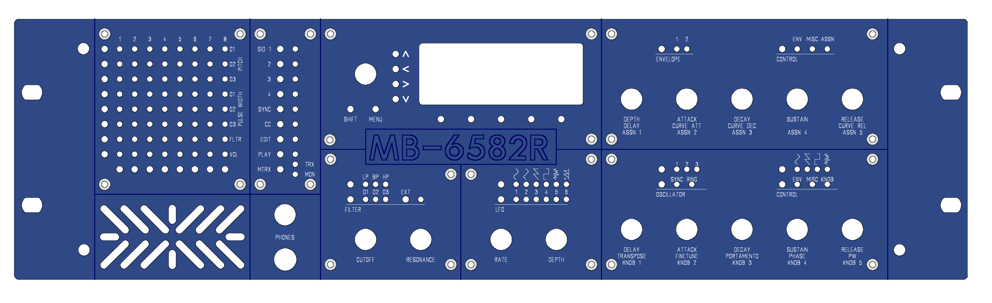
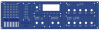
testI don't have the measurements yet for the 3U panel (I think I'll just have to buy it and measure I think) but I think I can eyeball it enough to keep working on the panel. I switching things around to looking more like the original C64 interface, albeit with a different arrangement. I have added a few front vents too - I liked the idea of pulling air from the front instead of the sides so I can make sure air will go over more of the heatsinks on the SIDs (I'm planning on using a fan out the back on the same side so airflow should be largely straight through). I am thinking of adding a front phono jack too for headphones but I haven't decided on that yet (depends on the results of post for one). I am also thinking about using illuminated buttons for some of the single button/led items (such as the SID selection). Since I am using the same LED wiring as the MB-6582, I am a bit worried about how noticeable the different outputs of the LEDs might be though. I noticed that e-switch has quite a few options and EAGLE already has the templates for quite a few of them (that's how I found them :P). I will likely remove the line-art too from the sections (such as LFO). I might, instead, put them in larger print on the sides since I have room for it, but I dunno. Still a work in progress but I was excited and wanted to share :) mb6582-R-FPD.zip
-
As part of my attempt at designing a rackmount control surface for my MB-6582, I was thinking of having a phono jack up front and in the back for the mixed output. That way, if I want to just listen in quickly, I can just connect some headphones and what not. I was also thinking of using a volume knob up front. I know Wilba says the output from the mixed out is attenuated but it's actually pretty loud to me when using headphones. So I was thinking of having a volume knob up front. I assume I just need to get some logarithmic dual input pot (for left and right)? Any ideas on values for that? Also, and perhaps more importantly, I'm not sure how to handle the switching between the two phono jacks? I don't want to pickup noise when one (or both) are not in use. I know some jacks have internal switches I could use for that? I read that Wilba did something similar with the discrete audio outs on the MB-6582 board (see ) so I was thinking of something similar. I was going to use panel mount jacks as well so any advice on where to find those would be great :) Stereo or mono does not matter to me as much (I assume with mono jacks I tie both into the common ground?). Thanks for the help!
-
I feel like this was asked before but cannot seem to find it after a good session of searching on the forum. So, has anyone used some of the pre-made LED matrixes from places like SparkFun? Such as: http://www.sparkfun.com/products/683 I realize that's a 3-color version but the dimensions are at least somewhat close to what I ended up with when I made my own matrix (which was, itself, based upon the MB-6582 matrix)? The only downside is that it's flat and 3 colors when I only need one. Also not exactly sure how to mount that since I do not see any screw-holes or anything. What about the serial variants (such as http://www.sparkfun.com/products/759)? I would imagine that would need a customer driver of course. I apologize if this has come up before. Feel free to flame if it has :) But thought I would ask and get impressions. I think I will still go with my own solution for consistency with the other parts of my control surface but thought I would check just the same.
-
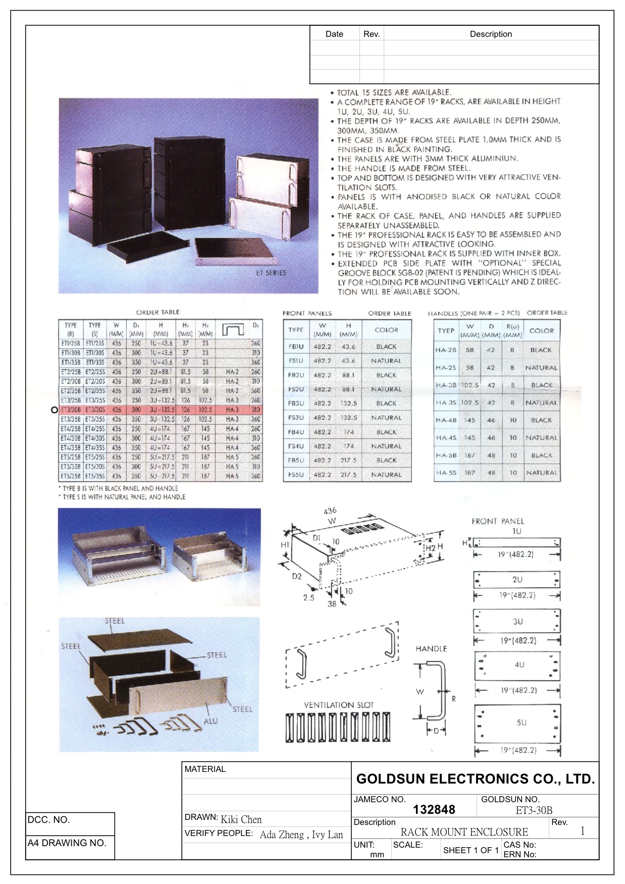
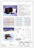
No better scans so it looks like that's going to have to do. It's definitely different from the hole panels on the default 3U rack layout in FPD. I can't really tell from those scans where the holes are though so I guess I'll have to measure it myself when I buy one.
-
Got the specs back. Attached. They are sort of low res so I'm having a hard time reading the most important ones (at least for me) - the mounting hole locations on the front panel. Otherwise it looks like the ones form Jameco will work out great. Going to ask them for a sharper image just to see if I can get my hands on one. I'm also now debating on 3U or 4U since I will want to put in some hot SSM action. I think a 3U would work as long as I lay things out well. *shrug*
-
Looks like he is also working on some other stuff (including NES stuff, which makes me excited almost as much as SIDs). Could be some neat stuff!
-
Jameco responded and said that, though it may take a few days, they should be able to provide the dimensions. Sounds promising!