

Narwhal
-
Posts
226 -
Joined
-
Last visited
-
Days Won
2
Content Type
Profiles
Forums
Blogs
Gallery
Posts posted by Narwhal
-
-
You might want to post more details showing your function and how you are calling it. It'll help people correct your specific error. But that said, I think I can provide some help here.
I can think of very very few cases with structures where you would ever want to pass them by value. The main reason you'd want to pass a struct by value would be if you wanted to modify the values without modifying the original structure values, but there are better ways to accomplish this even when you'd passes a pointer to the struct. Whenever you make a function call, the compiler must create assembly code which pushes your function parameters on a stack, then the function being called must pop them off of a stack. The more parameters, the more data-pushing-and-popping code needs to be create, and the more stack is consumed. When taken to extremes, this can equal a slow and inefficient app.
When you pass a pointer to a structure, it is often smaller than the structure, because structures often contain multiple items. I believe on the PIC's used here that pointers are 3 bytes? Anyway, it boils down that passing pointers to structure is most likely the best way to pass a struct and will result in more efficient code.
So, your function should be defined like this:
void SetColor(led_color_t * p_color);
This is not a multiplication :-) The * is letting the compiler know that the variable is a pointer.
then you can access the elements of the struct using:
p_color->COLOR[x]
or..
p_color->RED
p_color->GREEN
p_color->BLUE
-
100% wait til it's completed. There are going to be some pictures and video that go way beyond what this module is doing, and you all are going to want to see them. ;D
-
I'll definitely be getting to my clean up mode and moving to the new structure. It just wasn't at the top of my list because I'm trying to learn everything very very quickly. I'm definite in cowboy development mode.. sorry about that, I just think that it has to be with the amount of time I have.
Really it boiled down to me pushing forward too fast and missing the facts that I should have updated, and I should have set the define for the actual processor type rather than assuming it was the same as the 18f452.
When I release this, it'll be all cleaned up, playing by the rules, and able to be use usable by multiple chip types. I promise. ;D
Kurt
-
Problem solved.
Stryd had me remove the j5_io init call and I initialized the tristates and the adcon1 myself in the first lines of Init() in my main.c. And it worked! I'm so excited! I can't wait to finish off the simple stuff remaining.
Kurt
-
Ah Haaa! <light bulb goes on>
Ok, I am aware of the usage of PIC_DERIVATIVE_NEW_ADC in j5_io.inc. So I guess I assumed that the 4620 must not qualify as a a new adc because I hadn't seen any file that indicated it would qualify as that. I did search the pic18f4620 header file assuming this define would be in there.
The problem is that I don't have a hw_flags.h file. It doesn't exist in my project directory, and it's not in the j5_io modules directory. . Searching my hard drive, I found a version of the hw_flag.h file and I can see now that the 4620 IS a new style adc, and it's absolutely the case that my code is built with PIC_DERIVATIVE_NEW_ADC undefined. So BINGO this has to be the problem.
But..
To address this condition where I don't have a hw_flags.h, I only found two copies of it and neither of them were in the repository directories. One is in a j5_dout_v1d directory that is a j5 dout example app that I downloaded, and the other is in the midibox_sid_v2_0_rc25 directory, another download. I don't find the file anywhere in my entire copy of the svn repository.
#1) Where exactly is this file supposed to reside normally?
#2) Where is the appropriate place to include this header file? Obviously it's of vital use to the j5_io.inc file, but it isn't included there? Is that just an oversight, or is there something deeper I'm missing?
Thanks for the help TK!! This is the most certainly what the problem is and I can hardly wait to try it out.
-
I've reconfirmed that the hardware works perfectly when connected to J8 J9, so it seem to certainly be a software problem. On observation that may be a clue is that, when connected to any of the J5 locations, it always shows that one of the buttons is pressed when it boots up.. whereas when its connected to J8/J9 it never shows such until a button is actually pressed. Perhaps a timing issue when reading DIN via port-a or port-e?
I don't think it's of any real importance, but I am using a 18f4620.
-
I used the web access to view the diffs and applied them by hand.. It certainly looked promising, but it didn't work.
-
hmm ok.. I'll check that out. Mine is dated July 9. snvmios isn't letting me connect right now.
Kurt
-
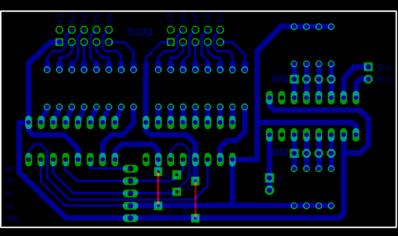
This weekend I've been trying to get the scan matrix to work when connected via J5 (A0..A3). I'm using the sm_fast.asm example and the j5_io.asm examples together.
The code setup:
in sm_fast.asm I've defined latch and port definitions as follows:
#define SM_SRIO_LAT_SCLK	LATA	; Pin D.3
#define SM_SRIO_PIN_SCLK	3
#define SM_SRIO_LAT_RCLK	LATA	; Pin D.2
#define SM_SRIO_PIN_RCLK	2
#define SM_SRIO_PORT_DIN	PORTA	; Pin D.1
#define SM_SRIO_PIN_DIN		1
#define SM_SRIO_LAT_DOUT	LATA	; Pin D.0
#define SM_SRIO_PIN_DOUT	0
Init() of main.c is:void Init(void) __wparam { MIOS_AIN_UnMuxed(); MIOS_AIN_DynamicPrioSet(0); MIOS_AIN_NumberSet(0); // set J5 A.1 to be input and all other lines to be output J5_IO_Init(0x2); // initialize the timer function for the debounce counters // we want to setup the timer with a frequency of 1kHz = 1 mS // prescaler 1:1 should be used // calculate the required number of clocks for this period: // clocks = period / 100 nS = 1 mS / 100 nS = 10000 MIOS_TIMER_Init(0x00, 10000); //10000); // initialize the scan matrix driver SM_Init(); // initialize the shift registers // I'm hoping to eventually be able to use the SRIO driver! - please oh please MIOS_SRIO_NumberSet(0); // DONT USE THE MIOS SRIO DRIVER!!! }The Hardware Setup:
I've created a small board that just a DOUT X2, and a DIN X1. It's wired into J5 A.0 - A.3.
I've connected this board to the norman J8 J9 location and it works fine. When I connect it to J5 though it seems that the software isn't getting the input correctly. Using a scope, I can see the DOUT being strobed low just, and when I press a button in the matrix, I can the lines going into the DIN pulsing low as that column is scanned by the DOUT. But I'm not getting any recognition, by testing the sm_button_value variable, that a button has been pressed.
Is there something I'm missing here? Shouldn't this work?
Kurt
-
RC2 and RC3 Core Port:Pin values are swapped in TK's pin list document.
needs attention:
http://www.ucapps.de/mios/mios_pin_list.txt
The wiki has it correct, but of course all yesterday it was unavailable.
-
There is a module called j5_io that sets up the J5 pins to be inputs and/or outputs.
-
Not sure what "blog this sucker" really means, but I will gather all the info into one place when I get done.. right now I'm too stressed. I now officially have two weeks to get this doing what I need it to do. More on that later :-X
For now, here is a tasty video of the current state.
-
It just occurred to me that if you aren't making use of the CAN interface, I don't think you have to worry about the pull up resistor. You could always give it a test without it.
-
The Vd (+5v) pin is right nearby.. perhaps that might be a good location.
-
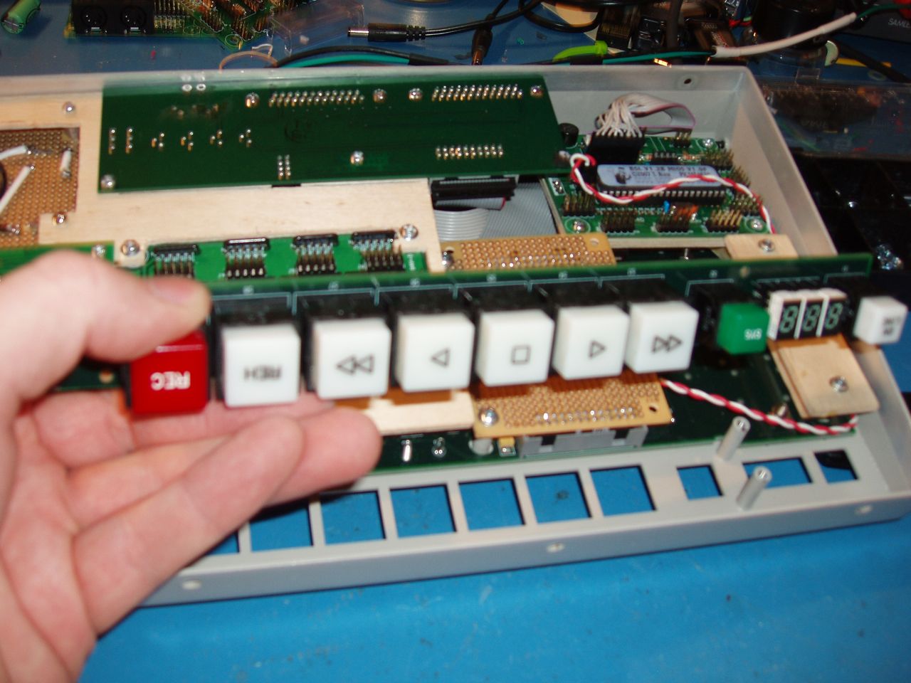
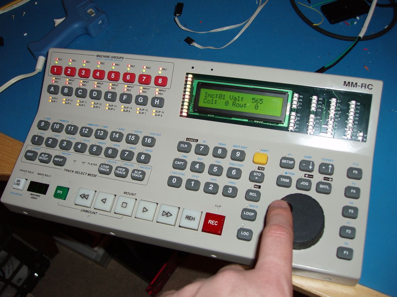
The real hack here: I need a support that holds the big play/rew/ff/rec/etc.. buttons at the bottom. I'm not really feeling like replicating their board and then etching my own version. If I did that then why not just etch all of the internals and make my own all-in-one. Nah. I take the main board and chop off the lower section using a jig saw then wire straight to the button backs.
Don't forget the encoder that I recently got working.
-
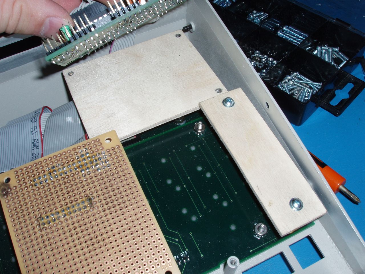
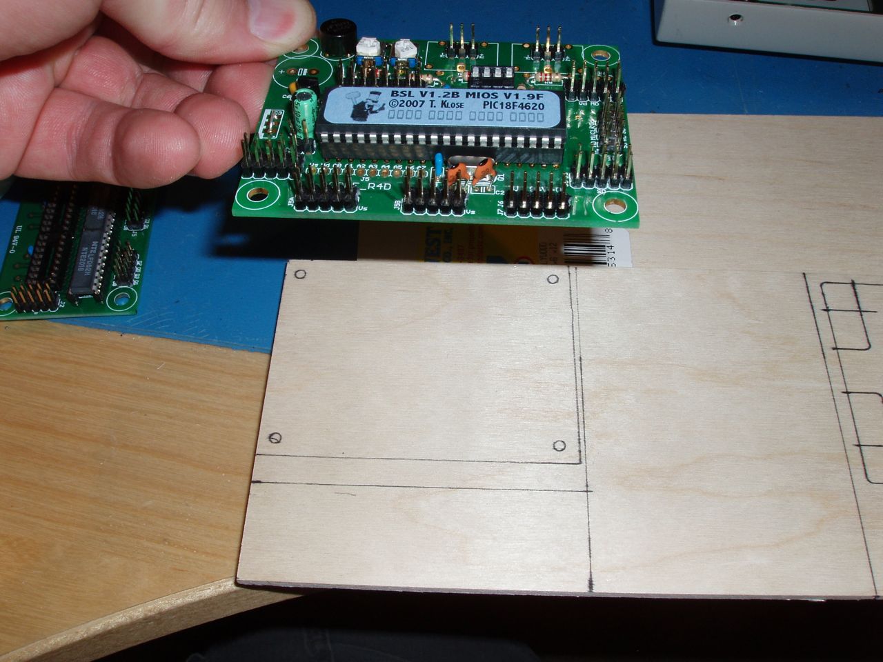
Bringing it all together...
-
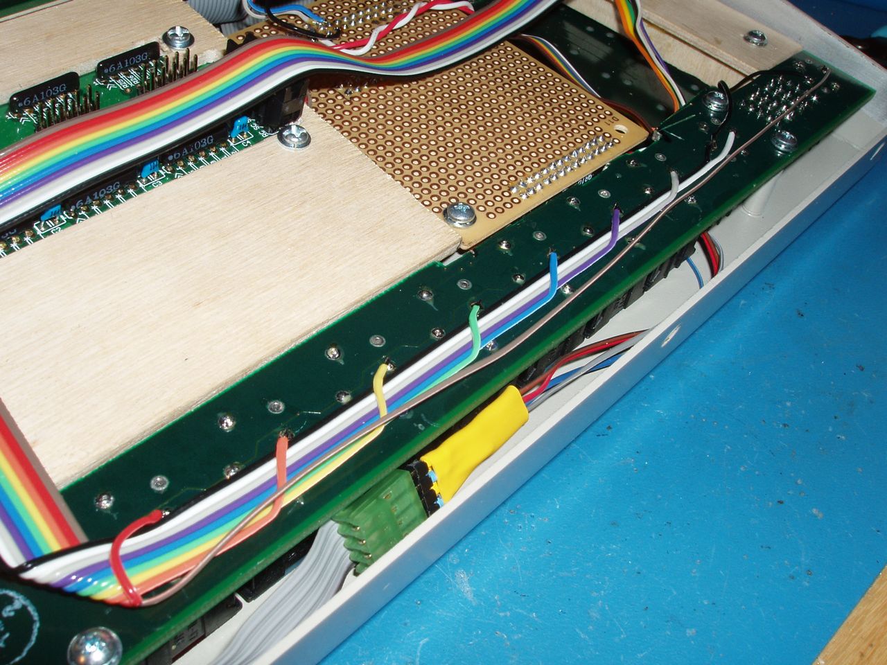
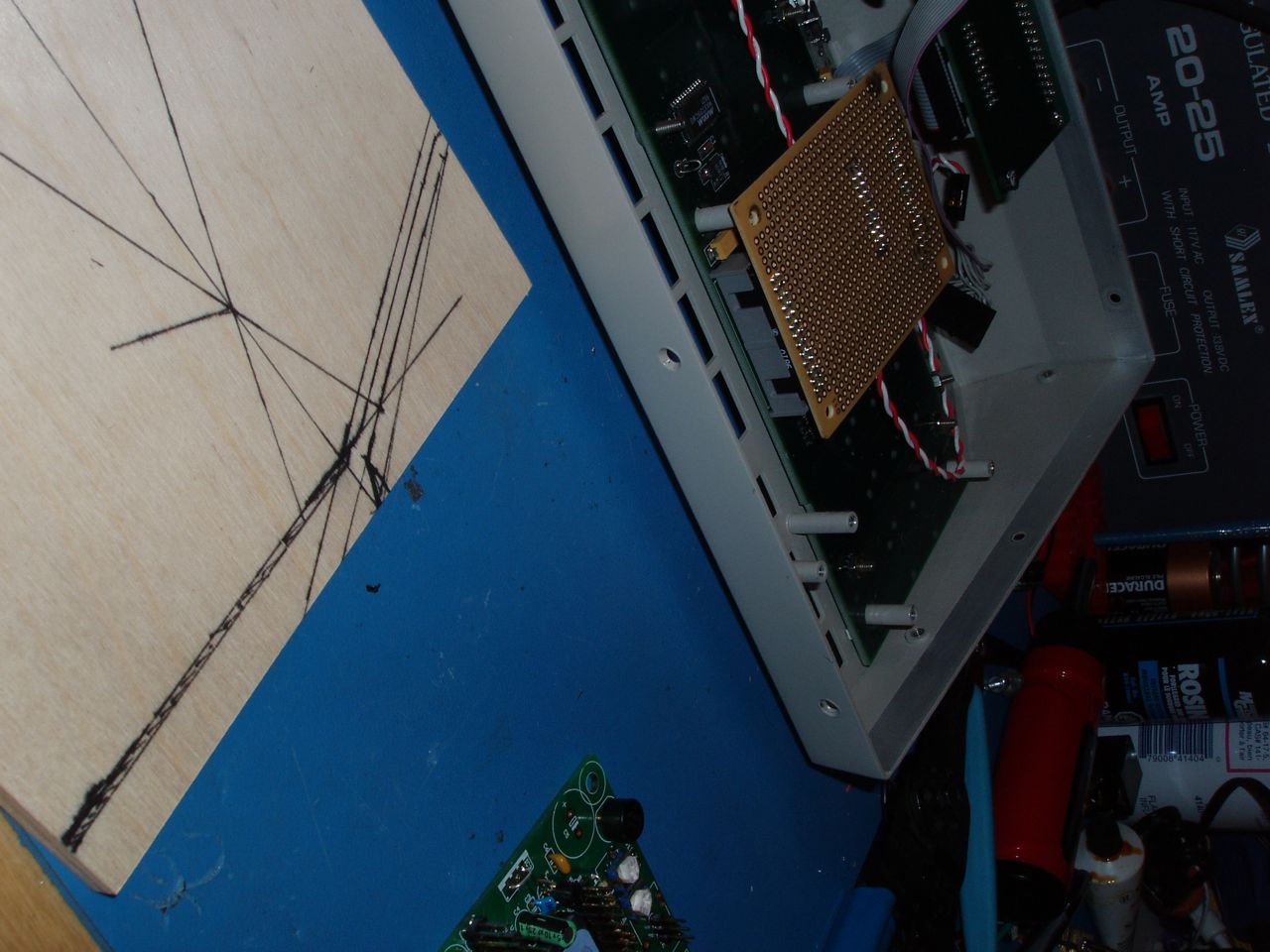
Here's where I think things start to get good. I was trying to figure out how all these things were going to be supported in here. I wanted to use plastic sheets, but I couldn't find any place that sold them around here. Actually I didn't even try that hard, I just happened across mini plywood while at the craft store. Plywood was perfect. It's strong, light weight, and can be easily glues into strange shapes.
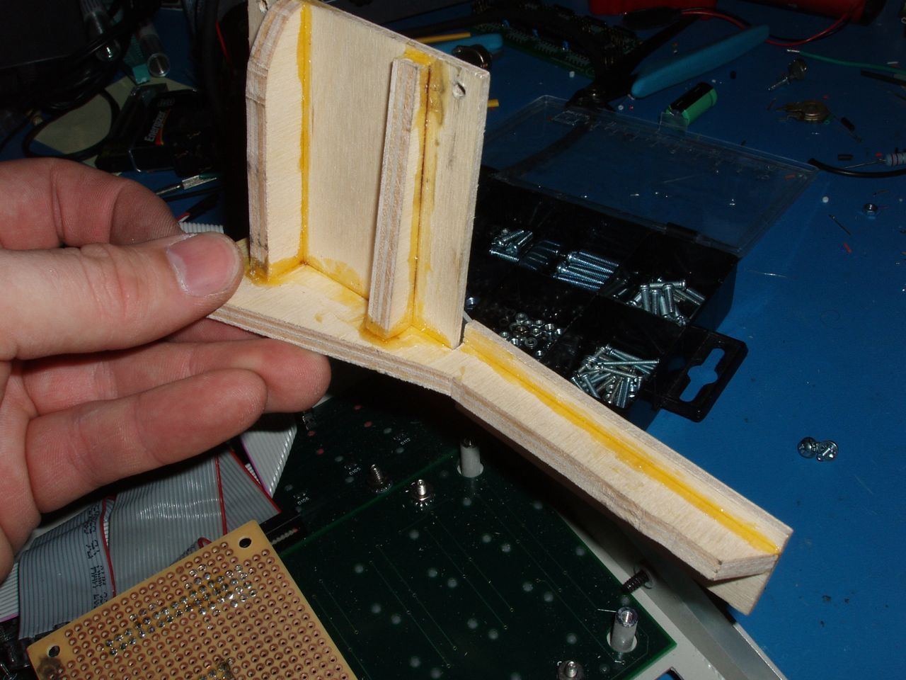
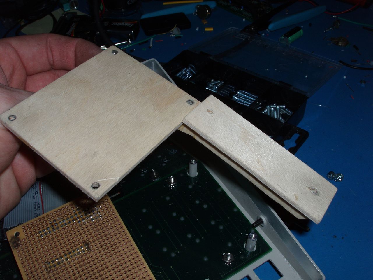
So after a little planning I built a large surface that would hold the power supply, a DIN, and a DOUT. Then I built a bracket that mounts to the right-most screw posts and supports a smash core board in the back of the unit.
-
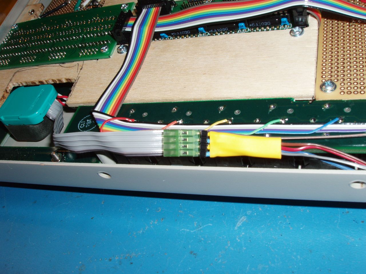
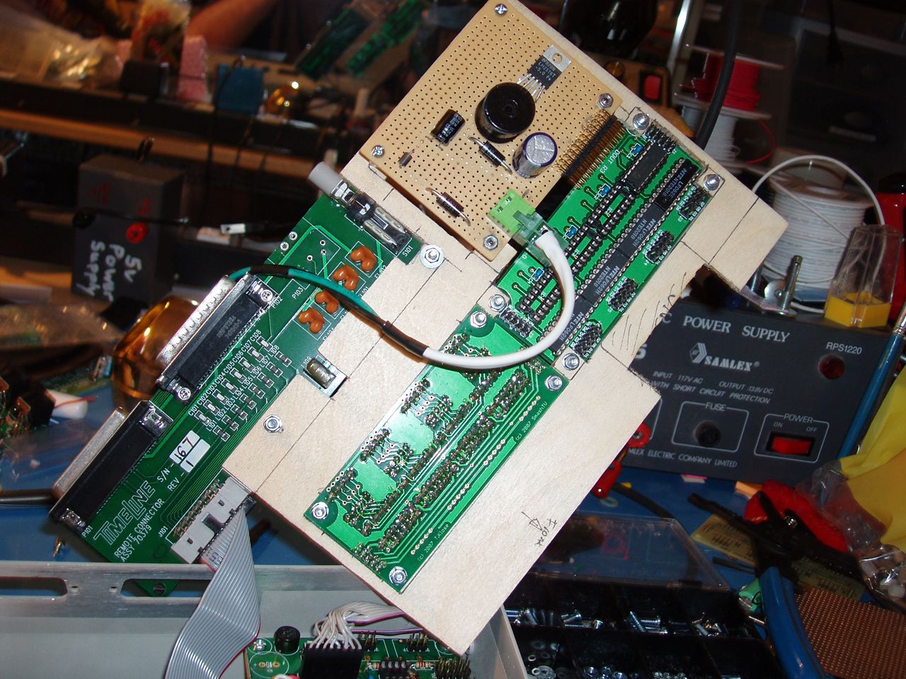
Here I'm planning the placement of the power supply, and core boards.
-
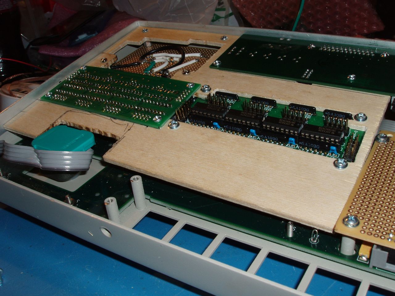
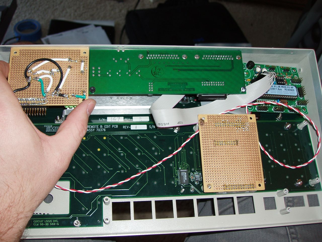
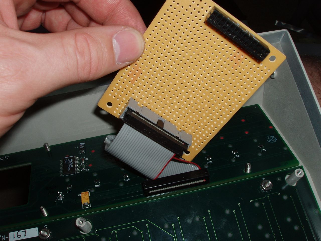
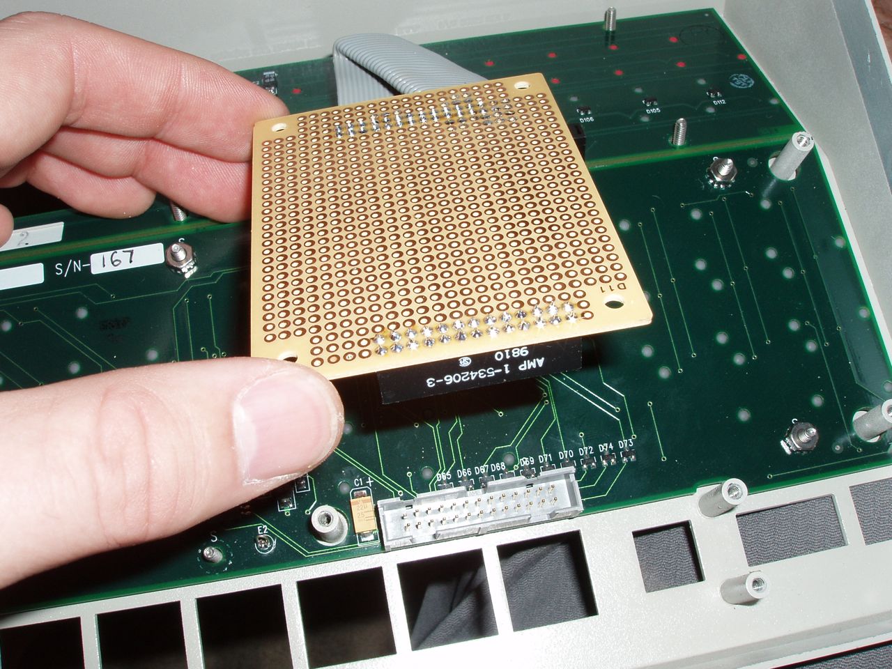
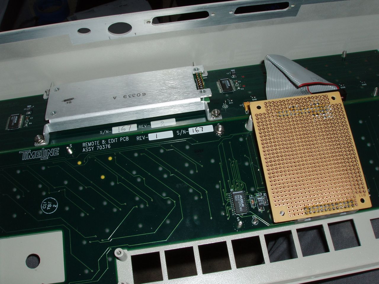
In the Tascam, the ribbon cables from each of the control surface boards all connect up to the main controller board. I desoldered all of the connectors on the main board and soldered them onto a vero board that I drilled so that is would mount on the center screw posts.
-
This weekend I did a lot of work on this project. Follow along if you will..
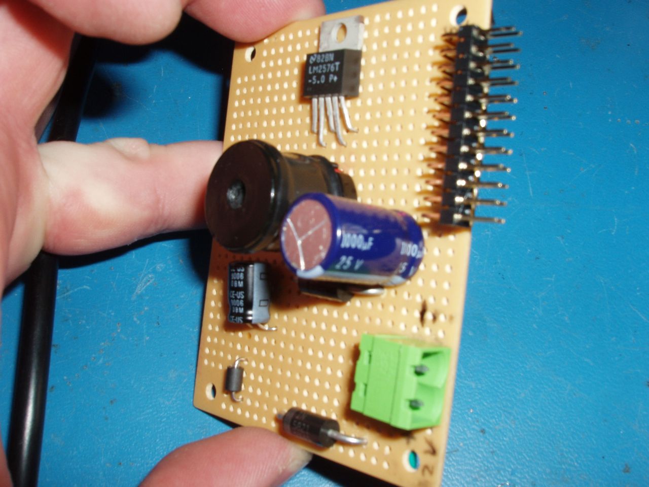
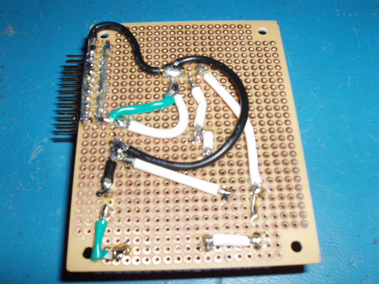
I have been having power problems trying to supply the LED drivers from the core. Perhaps its because of some other wiring problem, or perhaps it's because all those LED on full brightness were sucking too much power. Either way, the main board in the Tascam contains a very compact 3A switching power supply and that's just what I need to make all of my power woes go away for sure. So I desoldered all the part and moved them to a vero board.
Cheese eagle board file is available on request, but it's nothing special. I only made it so that I'd have a circuit reference once I desoldered everything.
-
Well the whole purpose of the first if:
if (!((oldsensor1 ^ sensor1) & !(oldsensor2 ^ sensor2)) )
is to figure out of the wheel had been turned. It should be this though:
if ( (oldsensor1 ^ sensor1) | (oldsensor2 ^ sensor2) )
I got it working last night and it is quite fast. There are exactly 512 state changes using a 128ppt encoder, when I spin the wheel a complete turn, I get exactly 512 on the LCD.. NICE!
If I spin the wheel at the fastest, the highest MaxInc on the LCD I get is 0x30. This is how many state changes are counted during 1 timer interval. You need to spin the encoder as fast as you can to see what its limits are. By adjusting the timer delta to a shorter interval you can tune this value down. Longer timer intervals will cause this number to increase. The idea being, that you never want this value to get anywhere near having its high bit set with the fastest spin you can possibly put on the encoder. As you approach 0x80 you run the risk of your increments appearing to be decrements. But you can increase the timer interval so it interrupts less often to run the timer function. There is plenty of headroom right now to support even higher ppt encoders.
I've attached the new main.c that is set to use an encoder that is attached to the pic's port C (J10) via pins RC4 (23) and RC5 (24). It's a lot like the encoder speed test, except that I don't yet have adjustments for speed.
-
The code as posted does not work. It's not stable and totally goes nuts if the encoder isn't turning at all. But don't worry I'm working on it. I'll post code and results soon.
-
That's because x0xb0x does not equal Midibox. They are not related in any way.
If you build a x0xb0x you can sell it for a million dollars if you can find someone to pay you a million dollars for it.
-
hmm no answer for this yet. The question sounds familiar, but a search I did when I had the problem didn't turn up any results.
It sounds like the skeleton needs a definition somewhere that defines which processor type to build for. In a makefile maybe?
For what it's worth, I use OSX too and I ran into a similar situation with one of the apps (can't remember which one though). But nearly every other app I've built has worked just fine. I have been using only the example apps so far and it's been working great.
Sick and Twisted
in Miscellaneous
Posted
About 10 Years ago I wrote a piece of music for a friends animated short movie. At the time she had tried to sell it to Spike & Mikes Sick and Twisted Animation Festival, but I never had heard whether it made it into the festival, or if anything ever came from it. The other day I found out that the video has been shown in the film festival as early as last year and I thought some of you might like to check it out.
WARNING: the movie is graphic and may be inappropriate for some viewers :-) But it's totally fitting for Sick and Twisted Animation Festival. I can't post a link directly to the video, but it's simple to get to.
1. CLICK HERE
2. Click on the CLASSIC Film Channel
3. Click on the Origami film by Jennifer Austin
Enjoy,
Kurt