

Narwhal
-
Posts
226 -
Joined
-
Last visited
-
Days Won
2
Content Type
Profiles
Forums
Blogs
Gallery
Posts posted by Narwhal
-
-
Progress report:
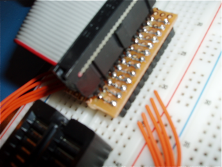
1) built an adapter on protoboard so I could plug the control surface cable into a breadboard.. someone really should make something for this problem! There is no place on breadboards to plug in cables.
-
Woot! That's good news stryd. Apparently that was done for the stribe controller eh... This is going off topic, but look what I scored from ebay that will be my stribe-like project. I think I paid around $10 for it!
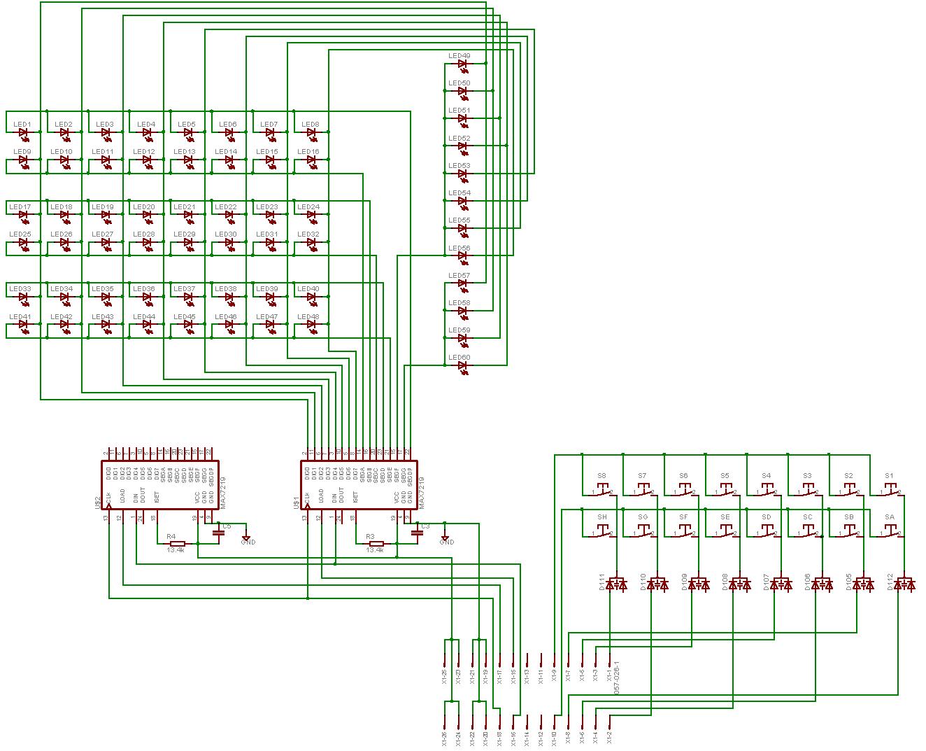
Anyway, back on subject... I've attached a few files. First is zip file that contains a replacement maxim component library for eagle that has the missing MAX7219, and the schematic file I created.
EDIT: note the left MAX7219 is not connected to any LED's because I'm seriously considering chopping it off. I don't want all those LED's where my sequencer panel is going.
-
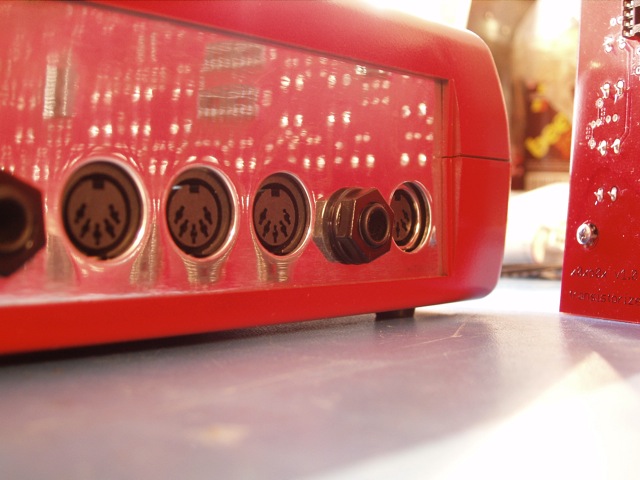
So back in March I caught a post in the ebay thread about a Tascam MM-RC remote tape control. I thought, damn that looks like it might make something cool so I bought one for dirt cheap. It has a ton of nice buttons, led's, a hefty encoder wheel, and an LCD display.
This past weekend I put in some time reverse engineering it and I thought I'd share what I've found. I've built a schematic for the upper control surface so far and I think it's going to be quite easy to make it do whatever I can dream up. I'm thinking either some sort of logic control, or perhaps even a sequencer.
I'll post the schematic when I get home later.
So lets start with the tear down pictures I've posted on flickr.
Next step is going to be using a DIN module to read the buttons, and some code to talk to the MAX7219 LED controller. At that point I'll have full control over the upper control surface.
-
it works if you let the boomp3.com player play the file in the browser, but if you download it, it makes a file named just "download" that doesn't work heh
-
I'd listen to it, but the file is 0 bytes long.
-
Eww.
Exactly what I said the first time I heard about them in the 80's.
but seriously.. back on topic. The case is looking very nice Foona. Keep up the good work.
-
Nice cords, but they remind me too much of Stryper!
hahahaha Sorry, I had to share that terrible piece of history. ::)
-
yes! I second that! more about the CNC! ;D
I have the parts on order right now through LumenLabs.com to begin a CNC myself.
-
The Koala pad for the Apple ][ should be very easy to hack even without opening it. Perhaps equally so for the C64 version, but I'll speak about what I know. Years ago I remember opening my Koala pad (I believe screws were under the rubber feet and very easy to open) that I owned just around the time that I was first getting interested in electronics. I remember that the pad component itself was separate from a very small circuit board that had few chips on it (I think 1 or 2 at most).
It seems to me this could be hacked from two directions:
1) open the pad and draw a circuit diagram and look up the data sheets on the chips inside.
2) Study the Apple joystick interface. Apple ]['s were extremely open devices long before anyone started touting open standards! I still have the original Apple motherboard circuit diagram that came attached in the back of one of the manuals. The process for reading the joystick was very well documented back in the day and often included descriptions of how the joystick circuit itself worked. I know the Apple ][ joystick port was a standard 16 pin dual inline socket on the motherboard and I believe that the axis values were measured using circuits that measure that charging times of capacitors as altered by the axis potentiometers. I'm certain I could scan you the joystick port (if the net doesn't already have this available) from the schematics and you'd then have the pinout and know where to apply 5V to make the pad give you a resistance.
-
I had one of those Koala pads exactly like that way back in my Apple ][ days! Just note: you had to use the "pen" with it because it wouldn't detect a fingers pressure.. though you could use your fingernail I remember it hurt. It liked a fair amount of pressure to detect position.
-
Looks very nice! I'd love to see some closer details of your knobs and light rings.
-
Seems like it could be done where its relatively spam free. Some kind of required syntax to the subject line perhaps. It's a shame that it relies on human interaction. I'm impatient and when I get the itch to write documentation, I like to add lots of pictures.
-
For some reason it didn't even occur to me that the email was @gmail.com. Of course it isn't automated.
-
How long does this magic usually take? I've given it 10mins so far. Are there any tricks to this emailing? Does the subject line help create a namespace or anything like that? Does my email address need to match some list that the receiver has?
-
Hi hopefully this is the right place to ask this.. I think I may need to have the upload permissions setup for me for the wiki. I've been writing instructions for XCode 3 and access via svn and I have several images ready to go, but the popup file manager window only allows me to select other peoples pictures.
Thanks,
Kurt
-
Welcome,
As ilmenator stated.. if you are stuck on hammer action weighted keys it might be best to go for a ready made solution. The latest studiologic seems to be numbered 188 now. There is one for sale on eBay.
Kurt
-
On my view of the layout that is shown above I don't see any trace going to the center pin of the voltage regulator (IC3) and there is no connection to the Bridge Rectifier - pin, it also looks like no connection to the - side of the Capacitor C5. I assume it is there somehow, as in the real board is different that this picture, or else you wouldn't have any power there. ??? I was just curious if you were aware of that or if somehow my eyes are failing me. ;D
-
Are there traces missing from the layout image above? I was just looking at the power section and it looks like a few things are missing.
-
I split my order to allow others room to get in. All totals have been corrected using Excel too.
-
Here's a neat article about how to turn a mac's external video port into a nearly free I2C interface that requires no drivers.
http://www.paintyourdragon.com/uc/i2c/index.html
Kurt
-
Actually your question reminds me.. I sizzled up the x0x with a distortion plugin in Logic. I'm sure if you sequence something less repetitive than what I did it would sound pretty cool with crunchy guitar(s).
-
A few weeks ago I finished up a xoxbox build. This weekend I finally posted pictures of the build and a lame but high quality audio sample of me fiddling with knobs over a drum track from my 9090. Rather than post a video on U-Tube and get berated by idiots who demand I immediately produce them a song and improve my video quality, I think I'll just share my efforts here. At least most of the people here appreciate the efforts and details.
Pictures here:
http://www.potm.org/Studio/Studio/x0x.html
I painted the case red, and polished the back panel to as mirror of a shine as I could get it. I think it turned out pretty sweet, and it worked nearly perfectly the first time I turned it on.
Audio here:
http://www.potm.org/Studio/Studio/Music_files/X0Xification.mp3
Kurt
-- Also thanks to The Prof for the parts that arrived just as some other ones that I bought on ebay got lost in the mail. :-)

-
My package arrived the other day. X0X was 99.9% completed and working last light. Audio and Video coming soon.
Thanks Prof! Mostly what I needed was the 6562's and your package arrived faster than the ones I ordered from ebay. In fact, I've ordered the ones from ebay twice now.. they seem to keep getting lost in the mail.
Kurt
-
Sasha this is pure art! Awesome!
You should throw in some sequenced computer fans of various sizes, and a cd drive opening and closing!
Kurt


Tascam MM-RC Conversion to Midibox
in Miscellaneous
Posted
2) spent a day debugging why 3 different core modules would only start up 10% of the time. I suspect a wiring issue with the LCD, but point to point continuity tests all showed that everything was fine each time I tested it. I still have no idea what was going wrong, but it's now working 100%.