

Narwhal
-
Posts
226 -
Joined
-
Last visited
-
Days Won
2
Content Type
Profiles
Forums
Blogs
Gallery
Posts posted by Narwhal
-
-
I'm having a hard time posting 3 pictures here in one posts, so I'm going to post 3 times.
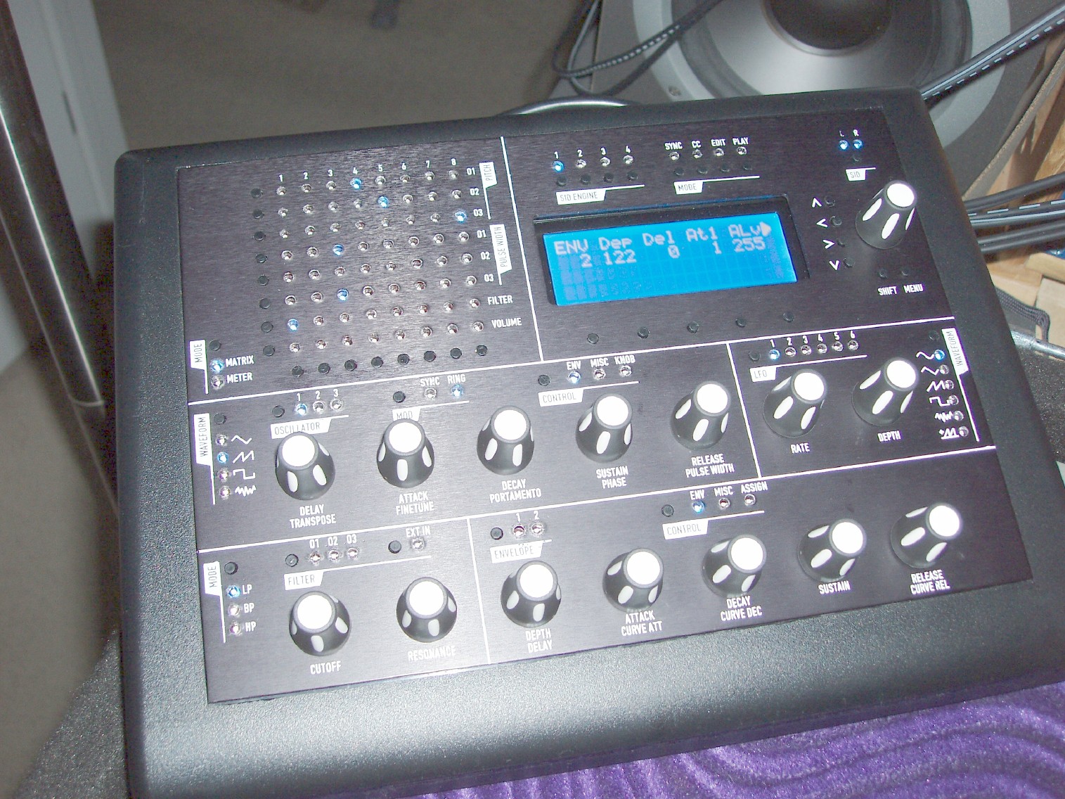
Here is a picture of my completed MB-6582.

-
I'd love to get in on a PCB order for these. They look amazing.
-
As an additional method (or alternative?) the PageUp/PageDown buttons could change the ensemble... especially in the Ensemble menu.
YES!
I was just pondering this very same question about easier Ensemble patch changes over the weekend. My initial intuition was to use the SHIFT and DATAKNOB, but I can understand how that SHIFT accelerator function is probably coded in to operate on all knobs globally. I'm all for the PAGE_UP/PAGE_DN buttons.
-
First the good news: I did get it working just fine, more on that below.
Tk, Sorry I misunderstood which boot screen you were asking me to press the menu button on. For several updates now it has always worked even when I held it down as I flipped the power switch on. Also of note, is that until today, I've always uploaded new application using "wait for upload request before starting" then powering on the Mb-6582. The first thing I tried today is holding the button later in the MB-6582 app version boot screen and it still didnt work. I'll use your recommended method from now on.
I am using setup_mb6582.HEX just to clarify because I don't think I've specified that in previous posts. I am uploading this to my MB-6582, so I assume that is the correct app.
Just for kicks I've uploaded setup_tk.hex - clearly not the app I want. BUT!!! when I uploaded setup_mb6582.hex after this and then pressed menu at the time you suggest.. IT WORKED! I must have had something in memory really hosing things up, that got cleared out by uploading another application.
If I can get it back into that weird state again, I'll dump the SRAM for you. So far its downgraded and upgraded between RC5 and RC6 and is cloning fine on both now. Not sure what qualifies for Wilba's *WHACK* but I could give this box a few right now :-)
-
More info:
Now that I've used the jumper method to attempt to update Cores 2, 3, and 4 It seems clear that RC6 is simply not run on my cores 2, 3, or 4 at all.
I've updated each one, and the MIOS Studio transfer said each transfer went fine "Upload process complete" with all checksums OK, but now when I boot I see
E002|A001 Ld Chn. 1
1***|Lead Patch
It will not switch to any SID other than 1.
Strange indeed.
-
I just switched to using the jumper method and I've noticed another strange thing
When I've used the jumper method before I could swear that the core 1 would be aware of the update and not continue to boot up. When I switched the jumper to core 2 and uploaded to device ID 1, I noticed that core 1 continued to boot right into the SID V2 app. Is that normal?
Thanks for the help TK
-
hmm no change when I wait for the "Mios V1.9f" display before pressing menu
it clones (the address counts up)
then its get stuck on
Cloning Slave 01
Waiting for Reset
If I got back to RC5, this part works perfectly. It moves on to Cloning to the other slaves.
If I reboot it, the application will show SID 2's status as * and it wont let me select it.
I'd try to debug it further myself, but I havent had the time to get the compiler working yet.
-
RC6 is giving me issues during the cloning process. It perfoms the cloning on core 2 then hang when it gets to "waiting for reset". Eventually it times out and boots up with a * on core 2. I've tested by switching back to RC5 and it works perfectly.
If you'd like any more information on the issue, just let me know. The situation is 100% repeatable.
-
Not sure how far forward or backward in time you've listened, but here are some of the artists I've collected over the years.
Eskimo
Talamasca
Growling Mad Scientists
1200 Micrograms
Hallucinogen
Prana
Man with No Name
Astral Projections
Alien Project
Astrix
TIP Records / TIP World
Flying Rhino Records
Twisted Records
Goa Gil
Ceiba
Kode IV
Logic Bomb
Noosphere
O.O.O.D.
Oforia
Protoculture
Psysex
Quadra
S-Range
Spacetribe
Sunkings
Tristan
Vibrashere
Wizzy Noise
hmm did I miss anyone?
-
After desoldering several switches and diodes, I found my problem with the switch seeming to be stuck down.
It was some kind of strange interaction between the LCD and the control surface panel, possibly involving the electrical tape that I was trying to temporarily use to isolate the two. When I removed the LCD and the electrical tape, everything started working perfectly. I've put it all back together nearly identically without the electrical tape, and its working great. Go figure.
-
All good tips and I wouldn't recommend anyone follow suit unless you are as certain as I am that I can engineer my way past those perceived roadblocks. :D
Thank you Wilba for bringing those gotchas up, it was certainly a help knowing about them so I could plan for that.
I'm not worried. I've actually already made myself a panel, I just haven't shown it to anyone. ;D
-
Narwhal, were did you get the switches ?
Many of the parts you see on the CS are from Mouser
Tact buttons:
http://www.mouser.com/search/ProductDetail.aspx?R=SKHHDTA010virtualkey68800000virtualkey688-SKHHDT
Encoders
all of the diodes were either ones I had laying around, or from a package of 100 that I bought from Mar Vac Electronics in Costa Mesa.
LEDs were an eBay deal. (Waiting for the CS panel before I mount all of the LEDs though).
-
So I thought I'd share some pictures of my MB-6582 as it is now. It seems to be working excellently, but I do have a question.
When I first started it up, using a the SID V2 software several versions ago, it would start on the screen that is shown below. Now when I turn it on it starts on a screen that looks like this:
Trn Fin Por Phs PW <>
0 0 0 0 800
I've learned that pressing SHIFT-ENTER while turning it on clones the application to the other cores. Is there another button combo that resets setting? Or is there a good reason it starts on the strange screen shown above?
Thanks for such amazing work Thorsten and Wilba and everyone whos hard work was involved in this. I'm really impressed by this synth.

-
lots of questions there.
A lot of confusion can arise here over boolean operations because C++ added some new functionality that may or may not be implemented in the later C compiler we are using for the microcontrollers. I'm not 100% sure what's implemented in the compiler you are using.
I use microsoft C++ every day and I can do the following to alternate the state of a variable that is being treated like a boolean:
char StateX = 0;
StateX = !StateX;
this works like the following psedocode:
if StateX is false then set StateX to be equal to true
else set StateX to be equal to false
I don't want to crack your brain while your doing so well with the booleans, but there are also bitwise operators that you can use. That will result in all of the bits of your variable alternating states:
char StateX = 0;
StateX = ~StateX;
pseudocode for this:
if StateX == 0x00 then set StateX to 0xff
else set StateX to 0x00;
I'll have to dig into the code to see what you mean by the State_t stuff. I assume that is some type that Thorsten uses for states. Unfortunately I'm too busy to do that at the moment, so maybe someone else can comment more on that.
- Isolating the A of 0x9a:
char data = 0x9a;
char midichannel = (data & 0x0f)
after this, midichannel will be equal to 0x0a. if data were set to another value, say 0x99, then data would be equal to 0x09. The & 0x0f part is a bitwise AND operation. Because 0x0f has the right side 4 bits set to 1, you are essentially extracting the rightmost 4 bits of the data variable.
Hope that helps.
-
It sounds like you know C even better than you may be aware of. You don't need to make a boolean variable. What you are doing with &&, ||, and ! are boolean comparisons. These boolean comparisons can be done with any type of variable (int, float, byte, char, long, pointers). So yeah.. you are in good shape with the boolean comparisons.
-
If you mean like this image.. yes that should be fine.

-
oooh awesome I want some! Count me in.
-
Definitely count me in on a set of panels.
-
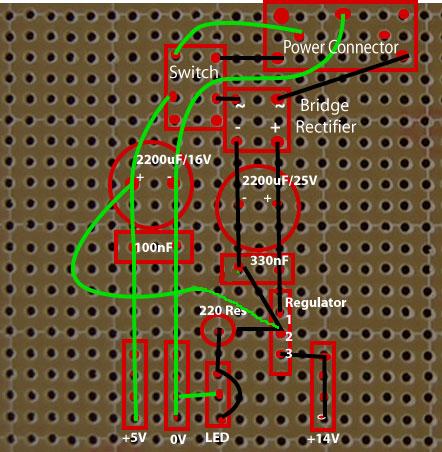
Yes this is a pretty good way to think about it as tracks, or signals that are each processed separately.
If you want to further understand what each of the components is doing in this circuit, I recommend http://en.wikipedia.org/ as an excellent source.
Here is how the rectifier turns the AC in DC: http://en.wikipedia.org/wiki/Rectifier
The device in the schematics you are looking at that has the squigly connections and the plus and minus outputs is a full-wave rectifier. It take an alternating current that has no net force in any particular direction and converts it into a pulsing positive current with a net forward or positive direction. http://en.wikipedia.org/wiki/Rectifier#Full-wave_rectification
You can think of AC current as a force pushing and pulling a boat that is sitting the water. Whereas the full-wave rectified DC current is a force pushing a boat in pulses such that the end result is that the boat moves forward. But since the boat is receiving pulses of full-wave rectified DC, it also pulses forward with lots of starts and stops. We need to smooth these pulses by taking a bit of the strong part of the pulse and filling in the stops. Since capacitors store up charge and release it this is where they come into play.
The capacitors in the circuit are smoothing out the pulse in this full-wave rectified DC current, so that the regulator will receive a steady flow.
http://en.wikipedia.org/wiki/Capacitor
The capacitors in that circuit are in parallel which means that they add together to form one big capacitor. They both have voltage ratings that ensure that they will be less likely to blow up giving the voltages that they will see. If you were to hook up an oscilloscope to the outputs of the capacitors, you will see voltage flows in almost steady DC, but with minor ripples in it. This is where the regulator comes in.
Then you have the regulators making sure that what comes out is the DC voltage that you wanted. It removed the ripples.
http://en.wikipedia.org/wiki/Voltage_regulator
In some ways a regulator can also be thought of as a protector. It can shut down if it sees too much current draw at its output, or blow out if it sees too much voltage at its input. This might not actually "protect" anything else in your circuit, but I have doubt that things could get much worse if it wasn't there in the first place.
Hope that helps a bit.
-
I'd like to get in on an order of these knobs. Ultimately, how many I'd like to get will depend on the cost, but I'd think that 50 would be a starting number.
-
I didn't dissolve away the clear part of the label on mine at all. The only parts that were really clear on mine are the inside of the big letters and inside of the pot holes. Once you clear coat the whole label, you wont even know if there were clear parts remaining or not.. they just dissapear.
Is there some reason you have to dissolve the clear part of the label?
-
1) I used a high resolution color laser printer (Konica 2550)
2) I used a heat gun that was sold in the electronics section specifically to shrink heat tubing. It gets hot enough to burn you, but not so hot that it will strip paint. The air from it often brushed my fingers enough to go OW! and pull my hand away, but it wasn't quick enough burn.
3) From the moment the label was printed, I handled the paper and the panel wearing latex gloves.
4) Before I drilled any holes, in fact before touching either the transfer or the metal with my bare hands to avoid oil transfers, I sprayed the panel slowly with light coats several time until it built up a thick gloss. I use clear acrylic Krylon as per the lasertrans instructions. Then I let it sit for 24hrs before I drilled it, and I think I could have let it sit longer to really harden up. I thought for sure that something bad might happen to the decal once it was drilled, but the acrylic really added a strong hard coat above the decal and the holes cut as clean as metal.
I intend to write up a really detailed webpage on my usage of lasertrans ... I'm a huge fan of the stuff now. I was hoping to do this as I printed the transfers for the back panel, but I've been lazy now that my 9090 is all together and working.
(I updated this post because I realized it read funky)
-
I have similar results with Lasertran on my 9090 as well. Turned out amazing, but I nicked the word power while it was in a delicate state -> before clear coating.
http://www.potm.org/Kurt%20Arnlund/9090.html


I used a hot air gun (purchased to heat shrink tubing), to really soak the toner into the paper before applying it to the metal. This REALLY glossed up the color.
Kurt
-
The pyramid of life hehe.
So TK.. you say "It works with a 6582 or 8580, but not with a 6581". Right now I have 5 6581's.. I've had to kill a lot of C64's and C128's just to get the 6581's I have. How on earth do I locate 6582's or 8580's??? I've scoured all the C64 parts sites I've found. Is there some secret that only a few people here know? I _want_ that sound.


My MB-6582 and a question
in MIDIbox SID
Posted
JB Welding in progress. I seriously doubt this is a picture of the final set of screws since several times the dried screws would pop right off the panel. Some places the screws were glued/welded rock solid, and in other places I re-glued them 3 or 4 times. The slow drying/normal JB-weld did seem to work better, but I do have more than a few screws that are held quite strong with the fast drying JB-weld. Even a few of the slow drying ones popped right off. There didn't seem to be any one thing I could blame for either one working or not working. I sanded, scraped up, and cleaned the troubled areas with alcohol and as the last resort used the slow drying JB-weld and eventually every screw I wanted was mounted with extreme strength.
The amount of times I took the panel on and off forced me to bevel the underside of all the LED holes because it was getting too hard to deal with all my flat top leds fitting back into the holes. I dont recommend this process unless you have a drill press and a lot of patience. Too much pressure, and too much heat and the panel WILL warp. My LED's are now mostly mounted flush with the top surface of the panel and I can easily remove the panel and remount it without too much hassle getting all of the LED sit back in their holes. They all have conical holes they sit in now and I kept the bevel away from the top surface so you really can't see that they've been beveled on the backside.