

Narwhal
-
Posts
226 -
Joined
-
Last visited
-
Days Won
2
Content Type
Profiles
Forums
Blogs
Gallery
Posts posted by Narwhal
-
-
somewhat like the mempot idea except using encoders and better manipulations I suppose.
-
Has anyone considered recording/effecting/playing back their scratches? I mean the movements of the turntable/encoder, not the audio it modifies...
Traktor 3's Native Mix files are essentially recordings of all the controls you interact with. It's a really great idea, I think I drooled a bit when I first played around with it.
But are you thinking about applying effects to the movement data itself?
-
I'll be giving this a try myself as soon as I can, but my excel work shows that the directions need to be reversed:
direction = 1;												// Default to forward
	if (oldsensor1 ^ sensor2) direction = -1;
I haven't confirmed this other than in excel, but it's something to keep an eye out for. For right now, Excel seems to indicate that it _should_ work :-)
Anyone want to double check the excel work? The logical equivalent of XOR in excel is OR( AND(NOT(A),B), AND(A,NOT(B) )
-
Can you post the new IP address? :P I can type numbers instead of the URL. We don't need no stinkin' DNS. ;D
-
You will need a midi interface of some type. A USB one will do.
Then you connect the midi interface to the SID with 2 midi cables (IN and OUT).
Then you use MIOS Studio to send the program (.hex) file to the synth.
Specific details of the process are on the uCapps website... The button to get there is at the top bar of this screen.
-
How did you build the midibox sid?
-
The encoder speed test app seem to already set the update frq to 1. I don't think I can take it any lower :-)
movlw 1 ; ms
call MIOS_SRIO_UpdateFrqSet
So does someone have a driver for encoders that are on port A, or do I have to write one?
-
More results:
MIOS_ENC_MODE_DETENTED : Value only increases no matter which direction I turn.
MIOS_ENC_MODE_DETENTED2 : Value only increases no matter which direction I turn.
MIOS_ENC_MODE_DETENTED3 : Value wont increase or decrease no matter which direction I turn the encoder.
EDIT:
** I've also removed the pull-up resistor on the DIN that this is connected to because the encoder performs it's own pulling-up and pulling-down. This gave no improvement at all.
-
I spent a little bit of time today attempting to use the high resolution optical encoder from my Tascam project with MIOS. The results seem not promising, so I wanted to check in here and see if anyone has any suggestions for something I may be missing to get it to work.
The setup:
I have the encoder wired to d0 & d1 of the 4th shift register of a SmashTV DIN module. On the reverse of the board I've added a small jumper to send 5v power over the unused pin of the input connector. This was necessary because the encoder needs power and ground to run it's internal logic. The encoders A output is connected to d0 and the B output is connected to d1.
I'm using the enc_speed project loaded on an PIC18F452.
Procedures:
As I spin the encoder in either direction, slow or fast turning seems to makes no difference, the direction of the value will change directions even though I have continued to spin the encoder in one direction. It seems to change increment direction most often when I release to re-grasp for further turning, or pause for a bit.
Questions:
I'm guessing that the rate of change of the encoder is either so fast for that MIOS misses some changes, or the pattern is not equivalent to the NON_DETENTED setting. To me it appears to be fine for the NON_DETENTED setting.
Any suggestions for what I might try?
Spec and pictures are in the part forum topic.
Video of the problem here:
mfuBxhUT3Mc
-
A single mixed main out does exist on the 6582. It's a small jack above the power switch. There are resistors near the output jacks that need to be adjusted down in value to get a decent mix volume. I'd suggest a value, but I'm still working on getting mine to sound right... so you might want to hold off on soldering those in.
See the section in the wiki titled "What’s the purpose of the J70 header?" for more info.
-
Nice things deserve being finished because anything worth doing is worth doing right. So don't let your time constraints bum you out so much. You can easily come back to it and make it work perfectly, and we will help.
-
I'm in for:
55 3FTL6 "Quiet"
+55 1E.09.6 Black
+10 1S11.16.0 Clear
-
The boards arrived out here in California today. They look nice Ulta. Thank you for all the work to put this order together.
-
Mine came from a company called Digital Dream Sound Studios in Burbank via eBay.
I haven't yet made it to an SRL show, but I've known about them for many years. That's really cool if yours came from him. You should have had him burn the $#!t out of it before mailing it to ya :-) I guess the $50 optical encoder that's in there might not have survived in that case, so it's probably better that you didn't.
-
I think your new mini design needs 3 more knobs: master volume, headphone volume, and headphone mix. I have a vestax vci-100 which has pretty much all the same controls as your design except for those three knobs. I find headphone mix and volume essential.. master volume is more of a set and forget.
Lookin good though!
-
While I don't know anything about where or if you can get the schematic file, I do know about C5 and LED1 because I asked the same question here before.
Those items are connected to a ground plane that is shown by the dashed outline in the image. Sometimes people also hide the ground planes in the images they post.
-
Hmm seems to work both ways now. Perhaps it's my power gremlins playing tricks on me. Seems like power is the next big thing I have to deal with.
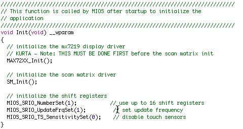
Today I began attempting to get the hi-res optical encoder working. I have it wired up and it looks like it's putting out the correct pulses. Unfortunately before I did that I chose to switch over to the sm_fast version of the button scan matrix code. The sm_fast version main.c Init() function contains the following lines:
// initialize the shift registers
MIOS_SRIO_NumberSet(0); // DONT USE THE MIOS SRIO DRIVER!!!
Does this mean I can't use the MIOS SRIO driver at all?? Or can I tweak some pin values to move around the fact that another driver is dealing with a few of the DIN and DOUT shift registers?
-
I'm taking a stab that these three lines should sufficiently say that I don't want to use AIN features at all:
MIOS_AIN_UnMuxed();
MIOS_AIN_DynamicPrioSet(0);
MIOS_AIN_NumberSet(0);
-
would that be a call to MIOS_AIN_UnMuxed() ?
-
The only difference was that I had SM_Init() before MAX72XX_Init().
-
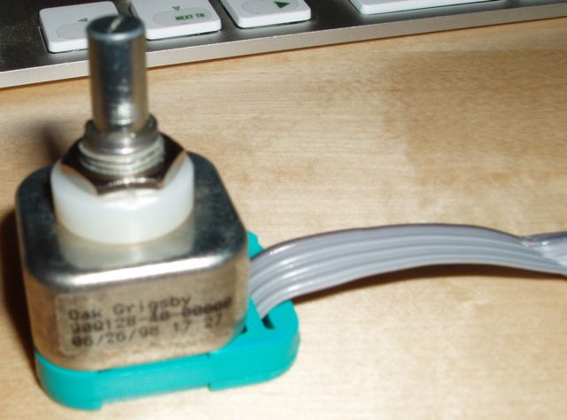
wilba: the encoder came for "free" in the Tascam tape remote. It was certainly a nice find. No detents.. it's smooth like butter and comes with a big knob that seems to be filled with a large mass of copper (it has some serious heft to it).
woah.. you got me thinking. How much would this particular encoder cost if I people wanted it.
The answer is $51.67 US not including the knob. Perhaps a bit out range, but I'm sure there are scrap items like the Tascam on ebay where it can be acquired.
Thanks for the tips.. maybe I'll give it a shot today.
-
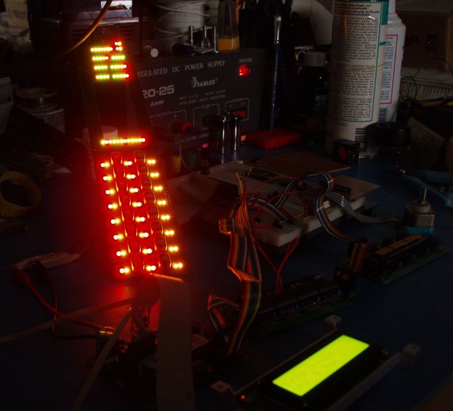
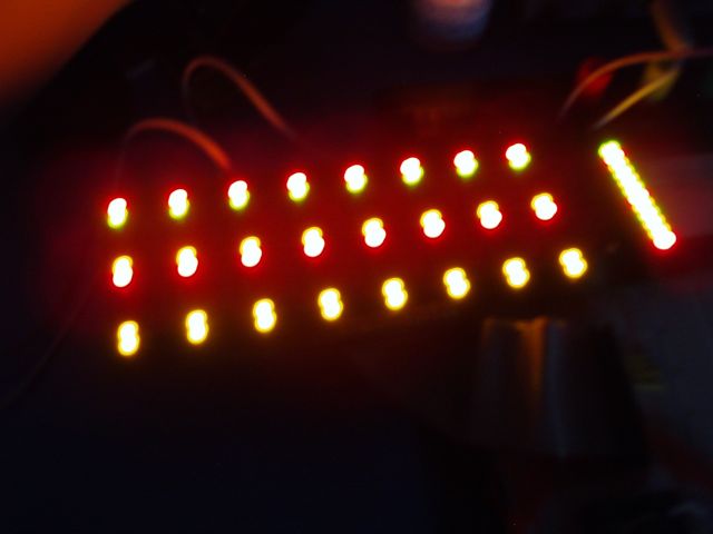
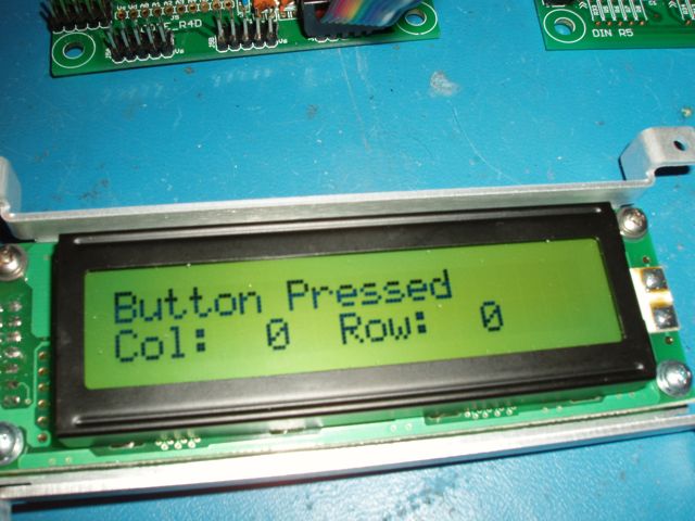
So today I decided to tackle control of the Max7219 LED controller.
After much futzing around trying to figure out where the pins for Port C.0, C.1, and C.2 actually physically present themselves, I wired up power and the 3 control lines (LOAD/CS, Clk, DataIn) from the core to the MAX7219. Noting too fancy. I still routed all the wires through my ZIF socket and protoboard for simplicity.
When I fired it up the first time.. NO LIGHTS! Doh. Continuity all test out fine. Frustrating. At a loss I decided to see if anything in code could be causing it. My first attempt I decided to move the location where I called MAX72XX_Init(). BINGO! That worked. Perhaps I can get an explanation for why the MAX72XX_Init() must be before the SM_Init() call for the scan matrix?
One "problem".. with all the LED's lit, my LCD display became almost impossible to read. I had to turn up the brightness to max so I could read it. Seems like the LED driver may like to have it's own power regulator. Maybe I'll steal the regulator setup that was in the tascam originally.
Hey this Midibox stuff is a piece of cake, I'm lovin it!! Thanks TK and everyone for all the work that's been done to get this system to the place it's at today. Hopefully I can contribute something useful for everyone soon. I have some ideas for improvements to the 72xx driver that I'm going to need for my next steps.
-
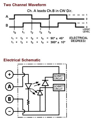
I have this Oak Grigsby/Electroswitch high resolution optical encoder that I'd like to use and I'm wondering what people think the possibilities of using this with MIOS are. I believe the normal encoders that most everyone here uses only have something like 22 PPR, and this one has 128 PPR. The encoder also has built in Schmitt triggers and needs +5v applied for it to work.
The specs are located here: http://www.electro-nc.com/oak/p0104.pdf
So I'm not really sure what the best way to hook this thing up is, or even if MIOS can deal with. Do I use some DIN inputs? Do I connect straight to the core?
I'm thinking if it goes to a DIN, then the DIN doesn't need the pullup resistors because it already outputs voltages that are pulled up and pulled down, correctly.. or at least it appears that way to me?
Thanks for the help
Kurt
-
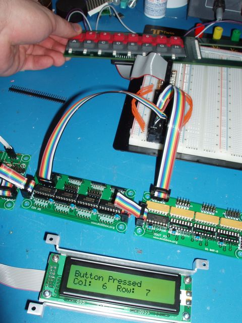
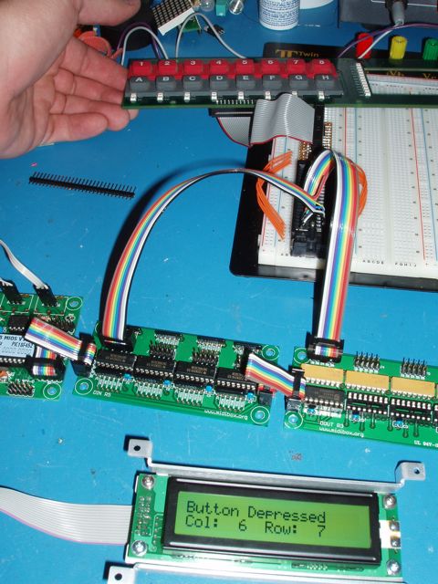
3) a) connected smashtv CORE to DIN to DOUT
b) cabled DIN and DOUT to a ZIF connector on a breadboard.
c) cabled ZIF to control surface cable adapter on a breadboard
4) searched around through the code repository for code that makes a button scan matrix work.. finally Stryd tipped me off that it was named sm_example. Can't we use long filenames!?! At least name the directory "Scan Matrix"
5) in main.c of sm_c_example1 I changed MIOS_SRIO_NumberSet(16) to MIOS_SRIO_NumberSet(1) because I only want to use one shift register right now.
6) I typed 'make' and let it build my project.hex file. A split second later uploaded project.hex to my core and walla! Hot button action.
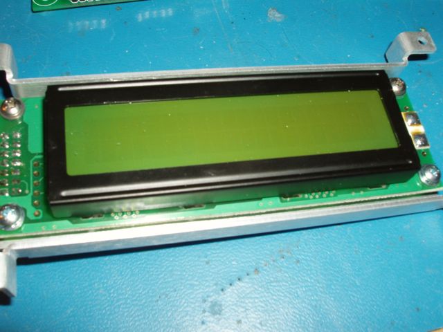
LCD+Core+MB64 Only squares are displayed and no text
in Testing/Troubleshooting
Posted
This sounds a lot like a PIC that only has the bootloader in it and nothing else. I had one of these last weekend that I was dealing with.
If you are sure that Smash uploaded MIOS and the MB64 app code to the pic, then you definitely should be looking at the LCD wiring. Use a multimeter to check continuity between each of the pins on the core to each of the pins on the LCD.. This should tell you if you have a good connection there.
Don't panic if it turns out that all you have is the bootloader.. it's very easy to send MIOS, then send the MB64 via Midi using MIOS Studio.