

wicked1
-
Posts
179 -
Joined
-
Last visited
Content Type
Profiles
Forums
Blogs
Gallery
Everything posted by wicked1
-
Then, is there sort of an idealized synth for this project? I know it can be used for anything, but like, it seems like people are thinking 3 oscillators... Since TK is using the kraftzwerg for his test platform, I'm guessing he's kind of designing around it... That brings me to a slightly off topic question. If you've got a little 3 osc synth, I can think of a lot of reasons you'd want to be able to fade each osc in/out of the mix. Would u rather have 3 VCF's or 3 VCA's? (Trying to think of a good way to assign the 8 available cv's) so like, 3xOSC to 3x filters to mixer to one VCA, or 3xOSC to 3xVCA to mixer to one filter.. then maybe a final vca?
-
Well, after much thought I've come to the same conclusion as always, that midifying my modular is an impossible dream.. (I've already got 3 midi-cv modules and sometimes those 24 cv's aren't even enough for a track..) Building a new semi-modular synth around this midibox cv2 project seems like a very good idea, though. I might have the wrong idea about this project, though. Since I found this thread from the other post where the guy was asking about some SID functionality, the first thing that popped in my head was patch recall. Basically, I was thinking i'd sort of permanently assign cv outs to osc's, filters, vca's, etc. Then be able to adjust all the settings and save it as a patch. Basically a little synth like the sid, only all analog. (and only one voice, instead of 4(or8)) Is that possible, or have a gone too far outside of the "midi-cv" box? -Edit, I just read the midi-cv page and it has answered a lot of questions, and I see it's basically designed w/ patch recall in mind. This new one w/ the LFOs and EG's and all is a LOT more useable in that area, tho.. I'm excited!
-
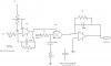
Ok, here's a quick schematic of what I think is going on. I didn't add the 2 electro and 6 smaller power supply bypass caps to my schematic, but those are obvious. There's the extra 27k res at the input that I need help figuring out. Also caps 21-24 are next to the VCA chip on the board photos and not on the parts list. Can someone who has built this, or knows what they are doing let me know if this looks right, and let me know where the missing 2 parts go? I'm guessing the 4 caps at the 2164 are bypassing the cv input to ground.. Not sure on the resistors at the input yet. It looks like they're connected to a trace that goes somewhere and not the ground plane. Thanks!
-
I'm wondering the same thing.. Anyone have a schematic for this? I found one that is quite similar, and I think I've mostly reverse engineered this one by looking at the parts list and photos. The cv inputs have me a little confused. Basically there's a 27k resistor, and I don't know where it goes. Looks like the cv goes in to a 27k resistor that is immediately connected to a 2nd 27k resistor at the input of the 074. I can't tell if anything else is going on at that junction (I'd guess so, else why would there be 2 27k resistors in a row, instead of one larger) I think that's the input filter to smooth cv, but I still don't quite get it, as I don't think the cap there goes to ground like a standard lowpass..... Maybe I need to sketch what I think is going on and have someone look at the schematic.
-
I've had a rev 1 pcb and parts sitting around for a long time. I finally decided to build it and read the wiki, and at the bottom of the base PCB page says "revision 1 errors" and has links that don't work anymore. What are the rev. 1 errors? I'll take any other pre-build advice people want to give for this project. :) Thanks
-
I'm personally more interested in the physical control surface. I like to play my synths like instruments.. (very hands on.. I dislike screens and menus when it comes to my old analog gear) Even if we could re-use the mb-6582 control surface PCB as one potential mb-cv2 control surface, it would be good. (I'd like more sets of knobs, personally, as tweaking two filters or two envelopes at the same time is quite common). The ability to do that and record all the knob twists to a track would be amazing! The ability to record and replicate anything I do w/ my modular in the MIDI realm would be amazing :).
-
Wow, this is awesome. I built the seq and aout for modular control, but have been thinking about building a dedicated digital control surface for it w/ patch recall, etc. This is perfect!! Any new updates?
-
MBHP_ETH, MBHP_SDCARD, SSM2044, SSM2164 PCB Bulk Order
wicked1 replied to seppoman's topic in Bulk Orders
I'm interested in some of these SSM pcb's! Filter and VCA, but mostly the filters. Are the original PCB designs available for printing? If not, they should be :) Otherwise, I'd like some more info from Technobreath. -
Hello, Im wondering if anyone has an order list together for the mb-6582 for mouser or anywhere else. I could have sworn someone had a mouser excel order list put together, but maybe that was a different project. edit Oh yeah, it was the sequencer that I found a parts list for... well... still let me know if anyone has one, thanks.
-
whoa, settle down there.... That first post is several months old, and over half a year past the time I started this. I thought maybe the first run of orders had gone through, and this was about new interests. Shite, in these modern times, 3 months is like, a generation ago. Who wants a pos 6 month old cell phone or mp3 player? Those are old news by now. (ok.. im just joking there, but 8 months is indeed a long time) (stryd, u've got 6660 posts ;)
-
So, What is going on w. the parts kits? I had a reply from Smash on .. 2007-12-01 at 15:35, which says Im on the list. I've got the pcb's, lcd, encoders, knobs, panels, case, etc.. I dont have a pic programmer, so will have to get that done from smash, which is why ive just been waiting to get all the parts from him.
-
core + 4x IIC + 8x bankstick pcb (formerly seq pcb)
wicked1 replied to ultra's topic in Design Concepts
Hi, I just wanted to follow up on my control surface post.. yes, I did use veroboard, and yes.. it sucked! I realize not everyone wants to use the same layout, but there already is a 'standard' layout posted on the ucapps seq page. I personally didn't use the standard layout either, but I'd bet that people who care more about getting down and using the seq would appreciate the possibility of a quick solution, even if not the PERFECT solution. (basically, I'd be able to throw a few together for my musician friends who have never picked up a soldering iron) personally, I made all my own illuminated buttons, so didn't need any LED holes or connectons/ Also laid things out differently than the posted layout. Well, I'll drop the subject here because I don't have the time to do it. -
core + 4x IIC + 8x bankstick pcb (formerly seq pcb)
wicked1 replied to ultra's topic in Design Concepts
When I built mine, making and stuffing the internal PCB's (core, din/dout, iic, bankstick) took about a week. Building the control surface, on the other hand.... that took months! I think a control surface PCB would be far more valuable for people who just want a functioning sequencer. And as sasha said, "But, I`m sure people would be interested as we all hate wires".... The wires connecting the few internal pcb's was nothing in comparison to nightmare of running all the wires to every button and LED on the control surface. I'm not trying to shoot down Ultra's internals PCB, but... someone needs to make a control surface PCB one of these days! A few of my friends want these sequencers after seeing mine, but there's no way I'd ever consider wiring up another control surface!! -
I finally just got my aout (old MAX chip version) finished and installed. I mounted the aout as a module in my synth, and use the synth power supply. I used rj45 jacks and a network cable for the interconnect between the sequencer and the aout in the synth. That gives me 8 CV's, 2 gates from the aout board and 3 more gates from the core. (the other 5 wires are the digital power and tx) After just one night of playing with it, I already know I'll need to get more gates over to the synth, but this works for now. Use your imagination. I had not only filters and VCO's being controlled, but then another VCO to FM the primary, and the tune of the modulator vco was being controlled by the seq. Use one CV for notes, but then you can use a 2nd track going to the same VCO to control octaves. I have a bunch of other not so standard modules, wave shapers, multipliers, etc that I was also controlling w/ the seq. Also had a cymbal sound going and ran that through a VCA, then I took a CV and sent it to the VCA to open it more on some hits so it gave an open/close hi hat sort of sound. The seq and a modular are a great combo!
-
Usually when tuning things like this there are two adjustments. The voltage and the span. If you set c0 to 2v, then adjust the span so that c3 is 5 volts, c0 would then most likely be lower than 2v. (well.. or more depending on which way you adjust the span) Does the software take care of some of that? I must admit, I haven't quite finished the module, so maybe it will make more sense when I get my hands on it.
-
for my modular, all the CV inputs/outputs are grounded on the panel. I don't run a separate ground wire to each jack. If you have no other ground connections on your panel, you'll have to ground one of the jacks, and all the others should be taken care of as well. This seems to be the common way to do things in the modular synth community.
-
If you know of any tutorials for screen printing panels, could you please post them? I'd love to try it sometime. thanks
-
Has anyone made a front panel layout with the neew buttons options?
wicked1 replied to intellijel's topic in MIDIbox SEQ
To further clarify how I figured out all of my DIN's and DOUT's what I did is print out my panel layout. Then as I soldered my buttons and led's I wrote down on the printed panel layout what each button and led connected to. The main ones like the encoders and general purpose buttons were the same as in TK's setup file. I had to change some things for the others. So, basically, next to each button on my printed sheet I have something like 2/3 in black ink, and 1/4 in red ink. That tells me that that button connects to shift register 2, pin 3, and the led connects to SR1, pin 4. Then I made the appropriate change in the setup.asm file. -
Has anyone made a front panel layout with the neew buttons options?
wicked1 replied to intellijel's topic in MIDIbox SEQ
Here's my sequencer. The panel is NOT professional! I made all of my buttons, so they are all a little different, and it was my first time using PCB mount components and none of them are straight. I just threw it all together in a box so I could bring it to a friends house and play around w/ it for a while. I can't do anything about the uneven buttons now, but I will be building a much better front panel and a nice case for it. www.sdiy.org/wicked1 scroll down to the bottom of the page The four buttons on the very right of it are the group select buttons. I'm building the 4x16 button matrix, and those 4 group select buttons will be moved onto that panel. I don't have any good photos of how I did the wiring. For everything on the panel I used verowire which was great! it certainly made the job a lot easier. I connected all of the buttons w/ a common ground, and all of the led's w/ a common ground (actually, it's by side, so all the buttons on the left share one ground, all the buttons on the right share one ground, etc...) The wiring for the LED's is all on the front, under the frosted acrylic, so you can't see it. Basically, I used the verowire to connect all the led's to 8 pin headers, which go through to the back of the panel. Then I use the ribbon cable to connect those headers to the douts. My past experience was w/ building my modular synth, and this sequencer looked easy in comparison. There wasn't a lot of complex thought involved in building the sequencer but man... that was a lot of wires to solder and keep track of! It ended up taking a lot longer than I thought it would. Do it right the first time, because you won't want to build another control surface! As for the software, it was actually quite easy. The setup.asm files have all the options available. I think I started w/ TK's. I just had to change which register and pins certain buttons and led's were connected to. Your wiring will be different than mine, so my file won't do you any good. You just have to be able to count to make the changes :). after that, you have to compile the software, which was really easy too. Just read this page http://www.ucapps.de/howto_tools_mpasm.html And yes, you'll need another dout -
I've got an MPC that I use to sequence things now. It will record CC's. Can I run two sequencers together and control one synth with them?
-
Has anyone made a front panel layout with the neew buttons options?
wicked1 replied to intellijel's topic in MIDIbox SEQ
elpy, I just finished my sequencer. What do you want to know? Well... It isn't finished. It's all wired up and functional and has a temporary acrylic panel. I'm having so much fun using it, I don't know when I'll build its case and a proper front panel. I'll try to add some photos to my synth diy website tomorrow. Compared to what a lot of the people here are doing, it doesn't look good at all, but it works! -
Thanks! that explains it. If that is really how few people have made sequencers, then all I have to say is that a LOT of people are missing out on the best step sequencer ever designed!! Thanks for all of your hard work. As soon as I'm finished dumping money into my build, I'll be sure to make a donation.
-
Hello, I'm trying to record a filter change in real time. I have the track set up, and it is controlling the filter. I can edit each step individually and have it control the filter, but I'd like to record it in real time. The midi in light does light up as I twist the filter knob, but it isn't recording any changes. I set up a track just for this CC, I go to the record page, I hit play and start twisting the knob. Am I missing something? I've haven't had a keyboard plugged into the sequencer yet. I'm not sure if it would record regular notes or not. Maybe that is something I should check. I'm surprised there isn't a user group of some sort for the sequencer.. how many of them do you think have been made?
-
Thanks, That fixed it.
-
I'm having some trouble w/ my trigger layer LED's. When I select A, nothing is lit, when I select B, A is lit, and when I select C, B is lit. I've checked my wiring, and it is fine. The way I'm trying to configure this SR is.. 0 -play 1 -pause 2 -Stop 3 -A 4 -B 5 -C 6 and 7 are the 1-16 17-32 led's Everything works fine except for the trigger layer. I tested all of the wiring w/ my multimeter, and it checked out ok So, just as a test, I switched it so that 0 -A (play led on my panel) 1 -B (pause led) 2 -C (stop led) 3 -play 4 -pause 5 -stop 6 and 7 are the 1-16 17-32 led's and have the same results. the A button lights up when I press play. The play button does not light when I press A, Play lights when I press B and pause lights when I press C This is the section of my ASM file ;; OPTIONAL! see CHANGELOG.txt DOUT_ENTRY TMP4, 5, 5, 3 ; Triger Layer A LED DOUT_ENTRY TMP4, 6, 5, 4 ; Triger Layer B LED DOUT_ENTRY TMP4, 7, 5, 5 ; Triger Layer C LED ;; OPTIONAL! see CHANGELOG.txt DOUT_ENTRY TMP5, 0, 5, 0 ; Play LED DOUT_ENTRY TMP5, 1, 5, 2 ; Stop LED DOUT_ENTRY TMP5, 2, 5, 1 ; Pause LED ;; OPTIONAL! see CHANGELOG.txt DOUT_ENTRY TMP5, 3, 5, 6 ; Step 1-16 displayed DOUT_ENTRY TMP5, 4, 5, 7 ; Step 17-31 displayed Thanks for any help
