

latigid on
-
Posts
2,516 -
Joined
-
Last visited
-
Days Won
147
Content Type
Profiles
Forums
Blogs
Gallery
Posts posted by latigid on
-
-
We can track the SEQ v4+ serial numbers here:
https://forum.midiphy.com/d/60-midiphy-seq-v4-official-serial-number-thread/2 -
No worries! Glad you could find some!
-
I get the same, but one trick is to highlight the entire contents and "print" the page to PDF. Then you should get the images in line.
Best,
Andy-
 1
1
-
-
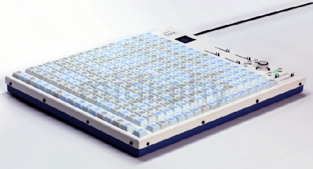
This one has been a long time coming but today we're ready to release MatriX.
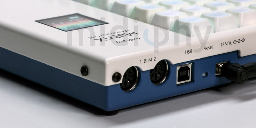
It has a similar form to the BLM16x16+X but now with mechanical keyswitches and full RGB backlighting as well as a joystick and OLED display.
Peter has done a great job in reprogramming the 32-bit application, in particular to extend the LoopA. Check out some features in the video below!
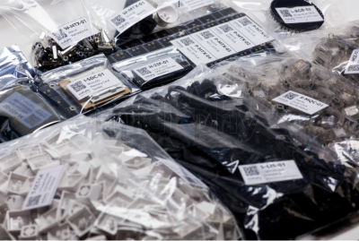
Essential kits are available here:
https://www.midiphy.com/en/matrix/Have fun building!
Andy
-
1
-
-
Very cool work Rolf!
-
Hello,
The answer is "maybe":
Looks like you'll need to compile the code and run it on iPad somehow. No idea how to do it!
MiOS Studio is just a USB interface really. Mostly for uploading firmware or monitoring. The sequencer application as pre-compiled firmware runs on microcontrollers only.
-
I'm not too savvy with buss control or loopbacks, but from what I saw I don't think it's possible to have two busses controlling one track. (Also I think 4 busses are the limit too.)
Would it be an option to have your MIDI notes set up on different patterns? Maybe you can trigger a pattern change with your drum hit and that alters something?
Btw. how do you trigger step advance manually? I saw that the divider can be switched to manual, but isn't it a CC that then controls the track progression? Or am I missing something?
-
We're using this for midiphy SEQ v4+
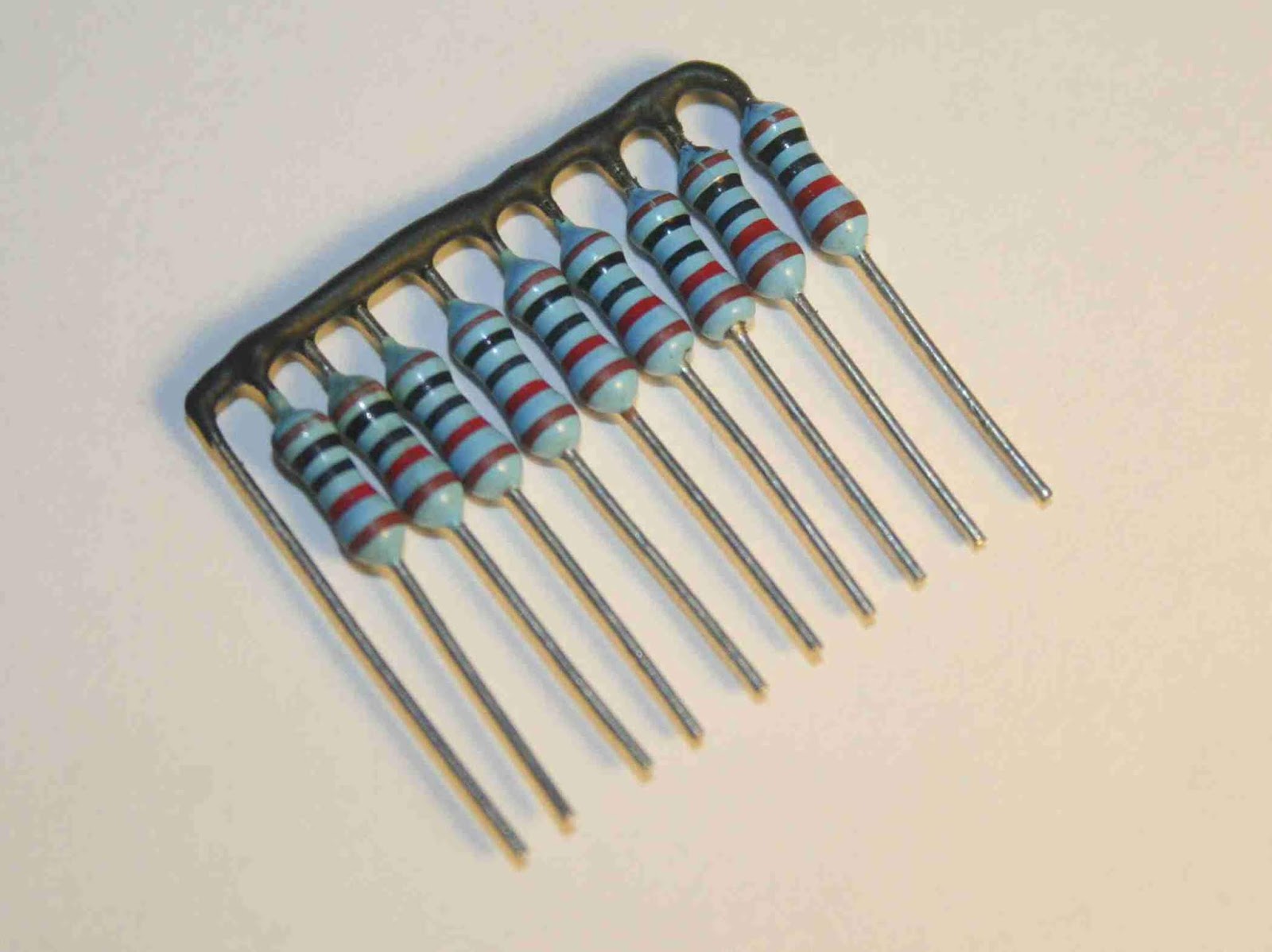
https://www.mouser.de/ProductDetail/Bourns/4610X-101-103LF?qs=%2BG4UmwsSIwOIq1qGQ3k3nQ==Maybe you can find an alternative?
You can also jury-rig bussed SIP resistor networks by mounting individual THT parts vertically and connecting the common ends together:
-
 1
1
-
-
Could be! Also please check the clearance in the case. The OLEDs we supply are thin (y dimension) enough to fit but there is not a lot of room. I think some models of display simply won't fit in the case.
-
Welcome! The midiphy PCBs also have a standard IDC, so that means you can mount the PCB anywhere and use a ribbon cable to a breakout DB-25 anywhere on the case, if that suits better.
-
Hello and welcome back!
We have Eurorack-format modules here (including a "Euroceiver" board):
https://www.midiphy.com/en/shop/188/MIDIbox-Sequencer-v4+-Eurorack-Modulesand the line drivers in question:
https://www.midiphy.com/en/shop-details/0/10/linerx-pcb-
https://www.midiphy.com/en/shop-details/0/9/linetx-pcb-Best regards,
Andy -
Pin 10 on U2 would seem not to have a pull-up resistor (all digital inputs need a defined logic state).
Otherwise, it looks basically like it follows the DIN module schematic (can't say anything about your proposed mapping or header connections).
-
I have a few spare, never opened from the original packaging. PM if you would like some. I think 25€ + shipping (in Germany) is fair.
-
Once finished, post a photo in
to claim your serial number!
I would love to offer SN 111 but I don't think we're there yet :).
-
Well done!
-
1
-
-
Hi Jeremy:
38 minutes ago, UnUnUnium said:Yes, I think it was the one for the STMF1 core.
It happens :)
38 minutes ago, UnUnUnium said:I did reboot the core (just pull the power/reset button, yes?) and I closed and reopened MIOS Studio.
That's right, pulling out the power/USB will do. Always restart MIOS Studio following a power cycle.
38 minutes ago, UnUnUnium said:Is the correct firmware here? http://ucapps.de/mios32_download.html
Looks like the current one, yep!
38 minutes ago, UnUnUnium said:JPA0 is on the core board?
Yes, you need to jumper it, means opening up the case unfortunately. Also ensure that resistors R101/R102 are installed.
Hope you can get back to the bootloader! If not, it's typically no biggie to reflash with ST-LINK or JTAG.
Best,
Andy-
1
-
-
Might have been the one for an STMF1 core?
Just checking, did you reboot the core and close/reopen MIOS Studio?
If you did, see if you can use JPA0 to enter boot hold mode and try to upload the app again. If it doesn't help, it would need a JTAG programmer or even just an STM32 DISCOVERY board if you have one around.
Note that there is only one SEQ app. The configuration is set by the HWCFG file that you upload onto the SD card.
Best,
Andy -
Ace!

-
1
-
-
Hi Jeremy,
The cables are the issue 90% of the time :)
But what you see there is two columns not driving, so that could also be on the resistor networks (particularly RN5, pin12/13) and other shift registers (particularly IC20, pin 3/4). The other two LEDs on the first 16*8 row are not simple to explain as the other rows and columns are functional.
Best,
Andy-
1
-
-
Great to hear!
-
Worked out with the JA matrix then? (Seems so, well done!)
The normal fix for OLEDs is to put a jumper in J15s (3v3).
Other options are to check R33D (560R), make sure there are no shorts from the back of the IDC cable to the OLED PCB and cabling in general.
-
I would still suspect the cables :)
You should be able to measure continuity between the IDC8 socket on lemec and the first 8 pins of the JA IDC24 (i.e. closest to the ring MEC switches). With a cable attached of course!
Are the matrices positioned the right way around? Upload a photo of your work on the JA and lemec_R.
Otherwise, if you mean the top 4 rows of the matrix don't light up, that is to do with the sink driver IC18 and shift register IC17.
For the driver: output side is pin 18 -> matrix bottom row (row 1), pin 17 -> row 2.. pin 11 -> row 8. Input side just the opposite leg on the IC.
For the register: pin 7 -> row 1, pin 6 -> row 2 ... pin 1 -> row 7, pin 15 -> row 8.
-
MacOS caches your USB MIDI ports, to see the four new virtual USB MIDI devices after your initial firmware upload of the LoopA app, please perform these steps: * start the Audio-MIDI-Setup of MacOS (e.g. search for "audio-midi" with Spotlight) * disconnect the core module from USB * delete the interface in the Audio-MIDI-Setup * connect the core module to USB again.
Hope it helps!
-
Looks like it's actually just gone out of stock. You might consider adding your location for more convenient shipping?
JP89 (DIN-DOUT) - Router
in Design Concepts
Posted · Edited by latigid on
It's not quite clear to me what you want to do? You want to have one J89 SRIO chain and switch between several Cores?
If that's right, it is trivial to make a Johnson counter/decade counter out of a 4017 chip. You could think to use the output enable pin(s) of the buffer (541 or 125) that is used to interface the buss to the core. Each Core gets one buffer with the datalines connected to the inputs (+DIN to an output), the outputs are common to the J89 chain (+ the serial in). Advance the counter to "turn on" one chip.