

latigid on
-
Posts
2,524 -
Joined
-
Last visited
-
Days Won
149
Content Type
Profiles
Forums
Blogs
Gallery
Posts posted by latigid on
-
-
Ace!

-
 1
1
-
-
Hi Jeremy,
The cables are the issue 90% of the time :)
But what you see there is two columns not driving, so that could also be on the resistor networks (particularly RN5, pin12/13) and other shift registers (particularly IC20, pin 3/4). The other two LEDs on the first 16*8 row are not simple to explain as the other rows and columns are functional.
Best,
Andy-
 1
1
-
-
Great to hear!
-
Worked out with the JA matrix then? (Seems so, well done!)
The normal fix for OLEDs is to put a jumper in J15s (3v3).
Other options are to check R33D (560R), make sure there are no shorts from the back of the IDC cable to the OLED PCB and cabling in general.
-
I would still suspect the cables :)
You should be able to measure continuity between the IDC8 socket on lemec and the first 8 pins of the JA IDC24 (i.e. closest to the ring MEC switches). With a cable attached of course!
Are the matrices positioned the right way around? Upload a photo of your work on the JA and lemec_R.
Otherwise, if you mean the top 4 rows of the matrix don't light up, that is to do with the sink driver IC18 and shift register IC17.
For the driver: output side is pin 18 -> matrix bottom row (row 1), pin 17 -> row 2.. pin 11 -> row 8. Input side just the opposite leg on the IC.
For the register: pin 7 -> row 1, pin 6 -> row 2 ... pin 1 -> row 7, pin 15 -> row 8.
-
MacOS caches your USB MIDI ports, to see the four new virtual USB MIDI devices after your initial firmware upload of the LoopA app, please perform these steps: * start the Audio-MIDI-Setup of MacOS (e.g. search for "audio-midi" with Spotlight) * disconnect the core module from USB * delete the interface in the Audio-MIDI-Setup * connect the core module to USB again.
Hope it helps!
-
Looks like it's actually just gone out of stock. You might consider adding your location for more convenient shipping?
-
-
Thanks, glad you like it! It's really built like a tank :).
I think documentation could be a cool community project, maybe you would like to start a wiki page? A user personally offered to write up some pages but I can imagine that life takes over and certain things drop off the priority list.
To answer some of your questions:
14 hours ago, clddstllr said:Trigger/Parameter Layer
It is now on the (right-hand) JA board: click the respective button and the lower row of Matias keys chooses the layer. Note that this is a significant UI enhancement compared to the previous standard panel.
14 hours ago, clddstllr said:Track Group and Track buttons
Likewise, choose the respective JA button. Rather than track groups, you get instant access to all 16 tracks and can easily make multiple selections now, a significant UI enhancement. The concept of track groups still remains and is indicated by the group of four tracks, with the currently selected track coloured differently.
14 hours ago, clddstllr said:F1-F4
In the SEQ v4+, most if not all button functions have their own dedicated buttons and there is no need for F buttons unlike in the previous version. If you wish to remap any of the buttons, feel free to edit the HWCFG file.
14 hours ago, clddstllr said:Length, Divider (and a lot of other) buttons
This has the same workflow as before: select the menu and press the respective key underneath the OLED displays to access these.
One important thing to note is that the previous "select" key is now called "shift".
It really is a deep instrument! I would encourage you to try out some basic patterns and explore the options, for example the direction and divider pages, the MIDI echo FX, different scales etc.
Have fun with it!
-
1
-
-
Well done #45!
Pimped out with tinted windows! :-)
-
1
-
-
16 hours ago, UnUnUnium said:
One more question - could my problems have to do with the core board as well, or are they likely to be only the JA PCB?
They could be indeed. That would particularly apply to J8/9 and IC1B.
-
3 hours ago, UnUnUnium said:
One thing I am still confused about is the SEQ_L.NGC situation - I get only 2 MIDI ports (In and out) and no specific NG ports.
Sounds like MB_NG is not loaded properly... if it is a Mac I think there is a way to delete some config or so. You can try with another OS or computer. I hope that you closed MIOS Studio between firmware updates.
-
1 hour ago, UnUnUnium said:
Thank you both for looking into this.
I've had a look at all my joints, but still no luck. I can look at alternative solder - I also have a flux pen if you would recommend that.
As far as SW 12 goes, unfortunately I think the copper pad is worn out, so it looks like I may have to order another JA PCB + parts and have another go.
You can always bodge the parts.
LED anodes connect across a row
4148 anodes connect across a row, D12 cathode to bottom-left pin when viewed from the front.
"switch cathodes" connect to SW17 below; for simplicity's sake that is the LED pin marked with a dash.1 hour ago, UnUnUnium said:Still, it would be good to figure out what went wrong here so I can avoid it next time.
I have installed SEQ_L.NGC, and succesfully loaded seq_l and set debug on.
One thing I noticed however is that 'NG' doesn't show up as a MIDI port in MIOS as it does in the build video. Could this indicate an issue? I'm not sure why it's occurring as I am following the instructions in the video and can successful load seq_l...
As long as you get 4x MIDI ports it is okay, sometimes they will be named differently. This varies depending on your OS.
1 hour ago, UnUnUnium said:LEDs definitely don't have reverse polarity, I checked again, and I was very careful of this in the first place.
As far as the physical issues you mention, the one which I suspect the most is a dodgy ribbon cable - could it be possible that this could prevent the LEDs from lighting up, yet still allow the switches to function?
Technically not. The matrix sink columns here are also driven by 74HC595s, so I would expect all or nothing. If the matrix was otherwise dysfunctional, you might see multiple button events triggered at once.
You could consider to carry on with the lemec boards and then you can see if the signals make it through JA.
-
There are some joints that don't look to be properly formed e.g. the top row of the LED matrixes, fifth pin from the left viewed from the rear of the board. It could be a similar cold joint for your SW12.
Were you testing with SEQ_L.NGC? Because if you have the switch matrix going, there is no reason why the LEDs should not light up, unless they all have reversed polarity. Test with your multimeter, diode mode, red probe on the circle, black probe on the flat.
If you haven't loaded SEQ_L.NGC, then I wouldn't expect any LEDs to light up.
Looks like the resistor network is the right part.
Cables can also be at fault, or even the soldering of the buffer chips or the headers on the Core board.
-
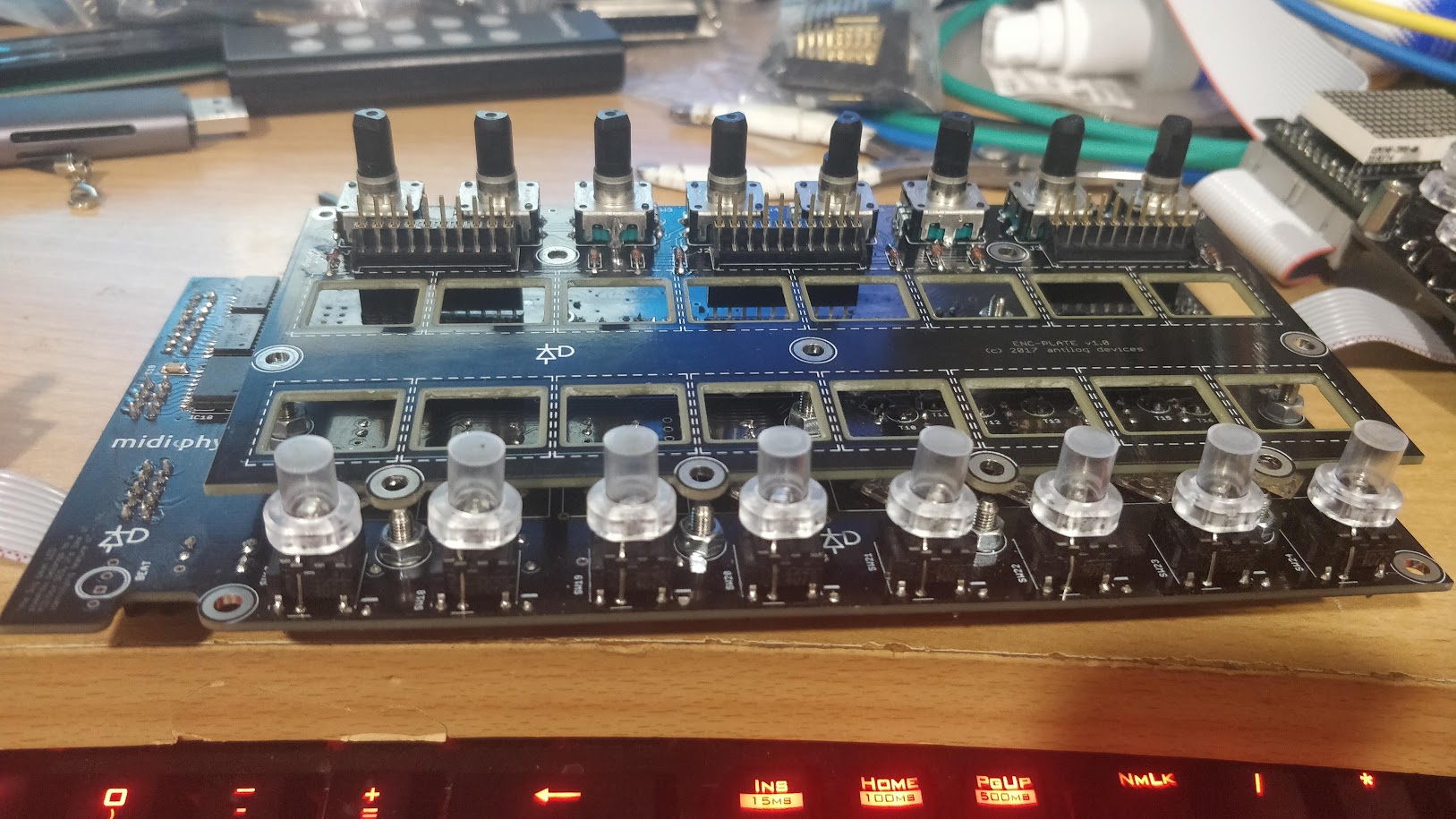
Could you please upload a couple of sharp images of both sides of the board?
-
Nice! There is little more than a USB connection and even that is in the middle of the board, so I think you should be good here.
-
1
-
-
It would be difficult to desolder these parts as the metal acts as a big heatsink. An option I can see is to somehow cut the metal apart, even so there are just the pins left, then order new brackets.
3mm is probably too much to get the rear-panel components to align properly. In the end maybe you have to reorder the PCB and/or parts but it is worth a go to get them off.
-
1
-
-
Really glad you could get it working and cheers for the generous donation! Top effort on your part really.
-
You could try to bodge it by connecting the cathode end of the diode directly to the encoder switch pin. It is the one closer to the middle of the board (the one closer to the edge is the row sink and is common to the three preceding encoders). It would probably help to remove the encoder switch pin from the PCB totally and find some way to insulate it.
Connecting directly from encoder switch pin to J2 pin 6 is also an option.
-
7 minutes ago, Smithy said:
Still no short between ENC4 pins and J2 Pin 6.
With the ENC Plate PCB installed when I short J1 pin 8 to GND the SW20 LED lights up and I get the following in debug, it includes touching the pin and releasing from it:
[1036341.011] MBNG_MATRIX_NotifyToggle(1, 28, 0)
[1036341.011] MBNG_DIN_NotifyToggle(2028, 0)
[1036341.012] [EVENT] id=BUTTON:2028 hw_id=BUTTON:2028 bank=0 fwd_id=LED:2031 type=NoteOn value=0 label=
[1036341.013] MBNG_DOUT_NotifyReceivedValue(2031, 127)
[1036341.014] MBNG_MATRIX_DOUT_NotifyReceivedValue(2, 31, 127)
[1036341.015] MBNG_MATRIX_NotifyToggle(1, 44, 0)
[1036341.016] MBNG_DIN_NotifyToggle(2044, 0)
[1036341.016] No event assigned to BUTTON hw_id=2044
[1036341.020] MBNG_MATRIX_NotifyToggle(1, 60, 0)
[1036341.021] MBNG_DIN_NotifyToggle(2060, 0)
[1036341.021] No event assigned to BUTTON hw_id=2060
[1036341.024] MBNG_MATRIX_NotifyToggle(1, 12, 0)
[1036341.024] MBNG_DIN_NotifyToggle(2012, 0)
[1036341.025] [EVENT] id=BUTTON:2012 hw_id=BUTTON:2012 bank=0 fwd_id=LED:2016 type=NoteOn value=0 label=
[1036341.026] MBNG_DOUT_NotifyReceivedValue(2016, 127)
[1036341.027] MBNG_MATRIX_DOUT_NotifyReceivedValue(2, 16, 127)
[1036341.029] MBNG_MATRIX_NotifyToggle(1, 36, 0)
[1036341.030] MBNG_DIN_NotifyToggle(2036, 0)
[1036341.030] No event assigned to BUTTON hw_id=2036
[1036341.033] MBNG_MATRIX_NotifyToggle(1, 52, 0)
[1036341.034] MBNG_DIN_NotifyToggle(2052, 0)
[1036341.034] No event assigned to BUTTON hw_id=2052
[1036341.038] MBNG_MATRIX_NotifyToggle(1, 4, 0)
[1036341.038] MBNG_DIN_NotifyToggle(2004, 0)
[1036341.039] [EVENT] id=BUTTON:2004 hw_id=BUTTON:2004 bank=0 fwd_id=LED:2015 type=NoteOn value=0 label=
[1036341.040] MBNG_DOUT_NotifyReceivedValue(2015, 127)
[1036341.041] MBNG_MATRIX_DOUT_NotifyReceivedValue(2, 15, 127)
[1036341.042] MBNG_MATRIX_NotifyToggle(1, 20, 0)
[1036341.042] MBNG_DIN_NotifyToggle(2020, 0)
[1036341.043] [EVENT] id=BUTTON:2020 hw_id=BUTTON:2020 bank=0 fwd_id=LED:2024 type=NoteOn value=0 label=
[1036341.044] MBNG_DOUT_NotifyReceivedValue(2024, 127)
[1036341.045] MBNG_MATRIX_DOUT_NotifyReceivedValue(2, 24, 127)
[1036341.060] MBNG_MATRIX_NotifyToggle(1, 20, 1)
[1036341.060] MBNG_DIN_NotifyToggle(2020, 1)
[1036341.062] [EVENT] id=BUTTON:2020 hw_id=BUTTON:2020 bank=0 fwd_id=LED:2024 type=NoteOn value=127 label=
[1036341.062] MBNG_DOUT_NotifyReceivedValue(2024, 0)
[1036341.063] MBNG_MATRIX_DOUT_NotifyReceivedValue(2, 24, 0)
[1036341.070] MBNG_MATRIX_NotifyToggle(1, 20, 0)
[1036341.070] MBNG_DIN_NotifyToggle(2020, 0)
[1036341.071] [EVENT] id=BUTTON:2020 hw_id=BUTTON:2020 bank=0 fwd_id=LED:2024 type=NoteOn value=0 label=
[1036341.072] MBNG_DOUT_NotifyReceivedValue(2024, 127)
[1036341.073] MBNG_MATRIX_DOUT_NotifyReceivedValue(2, 24, 127)
[1036341.080] MBNG_MATRIX_NotifyToggle(1, 12, 1)
[1036341.080] MBNG_DIN_NotifyToggle(2012, 1)
[1036341.082] [EVENT] id=BUTTON:2012 hw_id=BUTTON:2012 bank=0 fwd_id=LED:2016 type=NoteOn value=127 label=
[1036341.082] MBNG_DOUT_NotifyReceivedValue(2016, 0)
[1036341.083] MBNG_MATRIX_DOUT_NotifyReceivedValue(2, 16, 0)
[1036341.088] MBNG_MATRIX_NotifyToggle(1, 12, 0)
[1036341.088] MBNG_DIN_NotifyToggle(2012, 0)
[1036341.089] [EVENT] id=BUTTON:2012 hw_id=BUTTON:2012 bank=0 fwd_id=LED:2016 type=NoteOn value=0 label=
[1036341.090] MBNG_DOUT_NotifyReceivedValue(2016, 127)
[1036341.091] MBNG_MATRIX_DOUT_NotifyReceivedValue(2, 16, 127)
[1036341.186] MBNG_MATRIX_NotifyToggle(1, 44, 1)
[1036341.186] MBNG_DIN_NotifyToggle(2044, 1)
[1036341.186] No event assigned to BUTTON hw_id=2044
[1036341.192] MBNG_MATRIX_NotifyToggle(1, 52, 1)
[1036341.193] MBNG_DIN_NotifyToggle(2052, 1)
[1036341.193] No event assigned to BUTTON hw_id=2052
[1036341.197] MBNG_MATRIX_NotifyToggle(1, 4, 1)
[1036341.197] MBNG_DIN_NotifyToggle(2004, 1)
[1036341.198] [EVENT] id=BUTTON:2004 hw_id=BUTTON:2004 bank=0 fwd_id=LED:2015 type=NoteOn value=127 label=
[1036341.199] MBNG_DOUT_NotifyReceivedValue(2015, 0)
[1036341.200] MBNG_MATRIX_DOUT_NotifyReceivedValue(2, 15, 0)
[1036341.201] MBNG_MATRIX_NotifyToggle(1, 20, 1)
[1036341.201] MBNG_DIN_NotifyToggle(2020, 1)
[1036341.203] [EVENT] id=BUTTON:2020 hw_id=BUTTON:2020 bank=0 fwd_id=LED:2024 type=NoteOn value=127 label=
[1036341.203] MBNG_DOUT_NotifyReceivedValue(2024, 0)
[1036341.204] MBNG_MATRIX_DOUT_NotifyReceivedValue(2, 24, 0)
[1036341.205] MBNG_MATRIX_NotifyToggle(1, 36, 1)
[1036341.206] MBNG_DIN_NotifyToggle(2036, 1)
[1036341.206] No event assigned to BUTTON hw_id=2036
[1036341.210] MBNG_MATRIX_NotifyToggle(1, 60, 1)
[1036341.211] MBNG_DIN_NotifyToggle(2060, 1)
[1036341.211] No event assigned to BUTTON hw_id=2060
[1036341.215] MBNG_MATRIX_NotifyToggle(1, 12, 1)
[1036341.215] MBNG_DIN_NotifyToggle(2012, 1)
[1036341.217] [EVENT] id=BUTTON:2012 hw_id=BUTTON:2012 bank=0 fwd_id=LED:2016 type=NoteOn value=127 label=
[1036341.217] MBNG_DOUT_NotifyReceivedValue(2016, 0)
[1036341.218] MBNG_MATRIX_DOUT_NotifyReceivedValue(2, 16, 0)
[1036341.219] MBNG_MATRIX_NotifyToggle(1, 28, 1)
[1036341.219] MBNG_DIN_NotifyToggle(2028, 1)
[1036341.221] [EVENT] id=BUTTON:2028 hw_id=BUTTON:2028 bank=0 fwd_id=LED:2031 type=NoteOn value=127 label=
[1036341.221] MBNG_DOUT_NotifyReceivedValue(2031, 0)
[1036341.222] MBNG_MATRIX_DOUT_NotifyReceivedValue(2, 31, 0)
This does not happen without the Enc plate PCB installed.
I also tried doing it with the arduino headers installed to separate the PCBs further like in the photo below, and I do get the events and SW20's LED lighting up still.
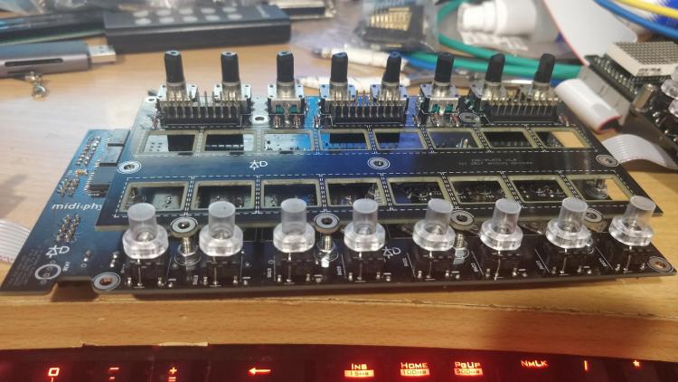
So this should rule out a short between components touching on both boards.
Would I be right in thinking there's a short somewhere on the ENC Plate PCB?
If you essentially trigger the encoder pins with the plate PCB disconnected and there is no spurious matrix event, then I agree that there is a short somewhere on the plate board. It is really puzzling that you don't see any short to J2 from the encoder.
Check again that all RNs are cut flush, even with stacking headers maybe the pins are too long?
The encplate PCB is fairly simple and just connects the encoders to J1/3 and the diode columns to J2.
-
I still think if you have a short between the encoder pins and J2, pin 6, that would probably explain your issue.
Try shorting J1 pins 8/9 to 0V, (not 10). That's where that encoder ends up. You should see DIN events corresponding to the encoder if SEQ_L/R is loaded. See if enabling the DIN matrix brings back the LED storm too.
Another weird thing that sometimes happens is that your MEC switches have broken LEDs.
-
hw_id=36 means that it is the 36th DIN input. I think the DINs are counted backwards, so that corresponds to IC3, pin 14. That pin is connected in parallel to J2, pin 6 and RN2, pin 5, along with the diode anodes of that column. (If they are counted forwards, then it is IC3 pin 3 and J2/RN2 pin 7 and the 5th column of diodes.)
Logically, the only way that you can trigger that DIN pin by turning EN4 is if there is some connection between the encoder pins and that pin. It could also be the diodes in the 4th column of switches.
With the plate board connected, see if you get any shorts between the encoder legs and all pins of J2.
Disconnect the plate and try the same debug test by shorting J1 pins 9/10 to 0V. If you get the same hw_id=36, then your issue is on lemec_R. If the issue disappears when disconnecting, then there is some unintentional contact made when stacking the boards together.
-
Very tricky!
To check: it does the same thing if you change the the sequence of boards and load the respective .NGC _R / _L?
You could try to modify the .NGC file by commenting out the DIN matrix
DOUT_MATRIX n=1  rows=8 inverted_sel=1 inverted_row=1  sr_dout_sel1=3  sr_dout_r1=4  led_emu_id_offset=1001
DIN_MATRIX  n=1  rows=8 inverted_sel=1 inverted_row=0  sr_dout_sel1=3  sr_din1=3     button_emu_id_offset=1001
That might help to narrow down where to look.
-
Yes, that is the right idea with the HWCFG.
LG,
Andy
Troubleshooting midiphy SEQ v4+
in MIDIbox SEQ
Posted
Might have been the one for an STMF1 core?
Just checking, did you reboot the core and close/reopen MIOS Studio?
If you did, see if you can use JPA0 to enter boot hold mode and try to upload the app again. If it doesn't help, it would need a JTAG programmer or even just an STM32 DISCOVERY board if you have one around.
Note that there is only one SEQ app. The configuration is set by the HWCFG file that you upload onto the SD card.
Best,
Andy