

latigid on
-
Posts
2,516 -
Joined
-
Last visited
-
Days Won
147
Content Type
Profiles
Forums
Blogs
Gallery
Posts posted by latigid on
-
-
First thoughts:
The 1M resistor will create a voltage divider, I guess you chose 1M to minimise the effect of this.
Definitely go for Schottky-type diodes for clamping. You're correct in that the reverse voltage will kill your IO otherwise.
You might want to check this out:
It's designed for an STM Core but could be easily adapted for PICs. The concept is to use a rail-to-rail opamp as a second inverting amp stage instead of diodes. There's no chance that a higher voltage gets through unless it manages to raise/lower the power rails (unlikely in a modular setup). The design has input attenuators and switches/jumpers for selecting the voltage range (unipolar 0-5, 0-10 V or bipolar -5 to +5).
I might have some spare boards available, currently I haven't tested them due to other commitments. Let me know if you want some and I'll look into it for you.
-
Let's keep up the discussion, I have an opinion but it's not meant to trump anyone else's.
I understand your view on a sloped front panel but my view is that this should be added as an option. This could easily be archived by designing the case to it flat as standard and have the option to attach something to the rear underside to give the case a slope. The advantage of this approach is that the angle for the front panel could be adjusted from 0 deg to what ever the user wants.For me this would look a bit tacky and lose stability. Maybe wooden end cheeks could be added but here I think a sloping sheet music stand would be the best option.
 By using blind studs on the front half of a U case female>female threaded spaces could be attached then the PCB attached with male>female threaded spaces (male end going through PCBS into female>female spaced attached to front) Then the back panel has holes for screws to then be fixed to the female end of the male>female spacer. By mounting the PCB this way the whole unit would be VERY strong and size wouldn't be a problem.
I'm trying to picture this, but if I've got it right you suggest standoffs on the rear of the panel. If you read up a few posts my idea is to use long studs (threaded rod) on the rear of the panel, through an acrylic spacer and then through the PCB and tightened on the back. This comprises a lot of material to avoid flexing and the threads are smaller in diameter compared with standoffs. I've kept in the other mounting holes on the PCB (2.8 mm), so if more strength is needed they could act as fixing points on the back. But in this case you couldn't go through the spacer as there's not enough material left for the grid shape after the hole has been cut out.
In terms of flat or sloped, we have to consider what else goes inside. Will everyone buy a miniCore board? Or do some prefer to use their old Core8s? What if others would like to develop a BLM-specific instrument e.g. with a Core32 inside?
Again, I need to check the full PCB dimensions but a square case will have wasted space at the bottom of the BLM. In this situation what is preferred? A flatter part at the front or a uniformly thicker case? This is my main motivation for a sloping box.
I really like the simplicity if this style of case and a byproduct of this simplicity should be reduced manufacturing costs.You're dead right, U-shaped cases are much cheaper than the "Consolet" style from Protocase.
EDIT: but in fact the "sloped top" style is the same price as the U-shape. The "consolet" has an extra flat part on the top and a removable rear panel. So there's already savings available.
-
Also a possibility. Just a question: is your idea motivated by aesthetics or price? From what I've seen of Monomes and the like, the flat surface is not very ergonomic, hence my idea of a slope. It can possibly be made flatter but I have to check the PCB first. Also remember that we're already talking 30 cm+ for to the back of the case, bigger than say your Novation controllers. Didn't you already put four together? How is that to play?
-
It looks that way but thankfully the socket doesn't go right to the PCB surface. Check a Core8 or on midibox-shop.com and you'll see.You're actually ignoring that zone for two of your resistors... -
why single sided? there is no cost benefit for thatWell he could have some fancy patterns etched on the other side!
Heh, nothing too fancy!
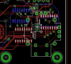
I'm still learning PCB design, but one rule of thumb is that you shouldn't have breaks in your ground plane where signals run across. If they go over a slot the return current has to take the long way around. Probably complete overkill unless you're getting into the MHz range, but I figure why not if it can be done without too much fuss.

The blue is a keepout zone as measured from the Core r4,
-
Thanks for having a look, I will move the resistors away from the edge of the DIP40. I always put caps as close as possible to the power pins for the best effectiveness. Some 4-wall sockets are actually mirrored (we're looking at the back of the board). It's always best if you don't have to, but bending components out of the way or putting them on the other side of the board is always possible. OSHpark won't be too expensive so I'll order a couple after a few changes.
-

and done I think. All 16 mil/single sided, I should check the clearances inside the DIP40 socket. I put in J5B in case anyone wants some extra pot/CV sources.
-
Great, will do!
-
I'd like to redesign the Core board to fit with my There are quite a lot of unused connectors and components. I will add a line driver (74HCT125) to buffer the IO.
First question: are pull ups on the unused pins still recommended?
-
Wow. Out of left field.. Do you have an exploded view of the assembly? I'm curious how this will fit toghether
I don't have an exploded view yet but perhaps I can explain in words. This assumes an enclosure from Protocase Designer.
Front panel is 3.2 mm aluminium (8 gauge in the US). There are 15 mm M3 studs running along the top and bottom edges and an M2 thread in the middle. I haven't yet specified the extra north-south studs as it messes with the symmetry :).
Next is a 3 mm acrylic spacer which extends from the left edge to the sliders. It provides a semi-rigid support to keep the buttons in place, especially the extra ones that need to be cut into 1x4 pieces.
Then the button pads. They have a 1.75 mm skirt and the buttons themselves are 10mm on top. This gives about 4 mm clearance over the top panel, more or less the same as ADAfruit's UNTZrument.
Then the PCB (1.6 mm). Note that the sliders are 7 mm tall from the top face of the PCB. The back of the 3.2 mm panel must be milled out ~2.2 mm leaving 1 mm panel space to fit them under.
The studs would pass through the PCB and be fastened with washers/nuts on the other side. The M2 screw right in the middle is important as it provides an opposing anchoring force.
If more stability is needed there are four M2.5 (?) holes for each set of 16 pads. I hope the PCB+spacer+panel will keep everything rigid though, especially if it's all flush. (-1 point for JBweld, the glue would get in the way here)
Then either a standard Core8 or a mini one as a piggyback module.
Wire to the DIN 8 and you're done!
-
Thanks for all the interest!
Boards ordered today, fingers crossed!
-
I'm not really enjoying the tone here... please have some patience and respect the fact that I've already spent significant time on this. I take all of the risks if there is a flaw with the PCB design. And I've been careful to try to come up with a case solution in parallel in order to avoid a "band aid" approach later on.
This is part of the success of the MB-6582 (and Xoxbox). Wilba specifically designed a device around the readily available Pactec enclosure. I bet many people have SEQ V4s which are all but finished apart from the case.
I'm curious now: will the other people interested also like a case?
After the panel is cut from FPE/Schaeffer or the Beast what is the next step? Will they bend sheet metal too?
If somebody can conceptualise a case that is more affordable, more suitable (rack/desktop) and accessible to ALL of the people who will build one, then let's see your design. Don't waste too much time, just consider a PCB of 300x286.5 mm dimensions with approximately 5 mm spacing to the inside surface of a 3.2 mm panel. I have to build one first to get the clearance from the back of the PCB. but I'd say 30 mm would be the minimum depth due to the piggybacked miniCore8.
Here's an idea: add holes (M4/M5) to the sides so rack ears can be attached. Or even wooden panels :).
@Adafruit Model or Dimensions:without YOUR pcb Files i cant design anything technicly/correct/exactly also it is a waste time.
A Design based on your PCB sent to "beastUk" or anyone else give us an offer... you dant have to do anything... http://thebeast.co.uk/?page_id=21
@Mounting the PCB:
There are more ways to dont need "mounting holes" on the frontside then JBWeld and Pressed/soldered screw threads.
e.g. with 3 U-bars on the back of the PCB that also strength the whole case to be like an Volvo240... with that the whole Frontpanel isnt static relevant anymore...
@Exactly what you want: 3 Letters "CAD"
@Core direct connections to UI-PCB: hell yea! flatter is better
-
Phatline: you can get model files from ADAfruit if you want to cut your own. I'll post the dimensions later. Fantom: I already plan to use Formulor for an acrylic spacer but not the case as I don't think it's strong enough. Lamouette: cutting the panel is no problem. Because there is no engraving it's a job for a laser cutter or water jet. The issue is getting a case to match which is impossible to find in this size. So my logic is: if you have to pay $200 for the holes, why not get them to make the box at the same time? This way you get exactly what you want.
-
I'm in Switzerland and I used Protocase Designer for the case. This is a proprietary format so I don't have the CAD file sorry. I did try to look for other cases but there is almost nothing in this size. Some are square but then are quite deep (100 mm).
The front dimensions I've used are 330x330 mm, bottom depth 40 mm top depth 70 mm. Altitude had a good idea that the Core8 could be rebuilt on a smaller board and directly connected to the big PCB. I'm working on this at the moment. This could allow for a flatter case, although I still think a gentle slope.is a good idea.
I envisage this as a desktop version as it would be awkward to play in a rack (IMO). Plus the height would be 7-8 rack units. I figure it will be expensive, so why not go for something nice. I don't want an UNTZtrument and I don't think the acrylic will be strong enough with a 16x16 sized matrix.
Yes, $500+ is a lot but Schaeffer want 150 EUR just to cut the holes in 3 mm alu. The material isn't expensive but the machine time is wherever its done. If 10 people order cases then the cost goes down by almost half, and they will also retroactively discount the first one built. So you can see my motives here :). Remember that they are not just cutting the panel but professionally bending the case and installing blind nuts, studs and standoffs. A JBweld-free MIDIbox. This price also includes a "grained" finish rather than tacky (IMO) powdercoat colours. They could anodise it for extra $$ and time. And to fit the sliders in at the correct height the rear face must be milled out slightly.
You're lucky if you have a milling machine and plenty of aluminium to practise with, but I'm guessing most people won't which is why I propose a professionally made case.
-
The blue+red version will even come out a bit cheaper as the LEDs are less expensive. But I'm with you: green-blue-cyan has the most balanced colour. I really like the red LEDs as they are deep and powerful but the mixing with green just doesn't work properly. Underneath the silicone buttons the light is quite diffused, I didn't notice any pain here.
The biggest outlay for me will be the case (>$500) as I will have to order one to check everything works. After that the price will be lower but I hope we can agree on one design/finish and I will preferentially sell PCBs to those who will buy a case too. When you say "contrast case" were you thinking of another case design, or a combined front panel? Anodised perhaps? If so there might be a way to get different finishes (e.g. black) but this would be an add on. I'm happy to discuss other styles, maybe people prefer a flatter box?
First of all I will get the PCB working and we can go on from there.
-
Cool, four-and-a-maybe is a good start!
Ok, cool ! :smile:What about the faders ? They can control some parameters on the seqv4 ? or can control external cc via the seqV4 out ?
Can we use them to record cc automation in the SEQV4, so maybe it will need a proper firmware ?
What about adding a joystick on the bottom ot the 4 faders ?
i have no idea about how the software side works...
but i could be in ! :rolleyes:
You'll have to check with TK on this one, basically you have some CC control over parameters on the SEQ. I did ask but it will be a development feature once people have the hardware.
Joystick feature-creep! There is a bit of space (about 30 mm square) on the bottom right corner of the panel but none on the PCB. The sparkfun/ PS2 thumbstick might fit but I can't find accurate dimensions for it. The panel to PCB spacing is only 5 mm, so I think this is a no-go sorry.
 This is really amazing work. I don't see how I could resist. I'm in.
Great!
Woah, really hard to resist (but the gurl would notice "another piece of hardware" and i would feel the Nudelholz, again ;-)).Awesome job with the routing, respect!!!
Many greets,
Peter
C'mon Hawke, Moar ghear right? You could say you picked it up from an ESA flohmarkt? But thanks for the support anyway. Let's get some built and we'll try to tempt you later :).
I almost got a good deal on LEDs from Aliexpress but the shipping cost and time doesn't make it worth it. I'm not sure if it's a good idea to order from Mouser at the 1000 piece price break before the concept is proven, otherwise I'd have a lot of spares on my hands...
What's the general consensus? Green-blue-cyan for the moment? Or are there some attached to red-blue-pink?
-
Altitude, Phatline, duly noted and many thanks!
Lamouette, merci à toi aussi. The LED brightness is between 100-300 mcd. I was running these at about 8 mA while the peak is 20 mA so there is a little bit of room with current limiting. Maybe the duty cycle could also be altered. At least without the silicone pads they are painful to look at :cool: . I'm not sure about direct sunlight visibility but I can try if it's nice tomorrow :). The brightness is good in a naturally lit room in any case.
For data the idea is to use an 8-pin DIN connector. If you have the Quad IIC module installed in your SEQ you connect the BLM for bi-directional MIDI and power (see here). The connector is a nice Amphenol pannel mount but the male plugs are a bit pricey at about $9 each. If anyone knows of a cheap supply of pre-made cables we could drop the cost slightly.
I'll aim to get the PCB layout proofed and ordered this weekend.
-
Cool beats! :flowers:
-
Case renders (too many images in first post):
I’ve also come up with a case solution using 3.2 mm aluminium plus a spacer to align the button pads, which is cut out of acrylic. It was a bit of a headache to find the right combinations of spacer height and panel thickness but I think 3.2 mm should be strong enough with all of the holes. The case includes self-clinching blind studs to fix the PCB to the front panel, standoffs on the bottom for both r2/r3 and r4 Core8 modules, a rear cutout for a DIN8 plug and rubber feet.


I checked but didn’t see any other truly suitable commercially available enclosures. Another option is a case by Heidenreich. Keep in mind the 289 holes dictate a fairly stiff metal should be used.
-
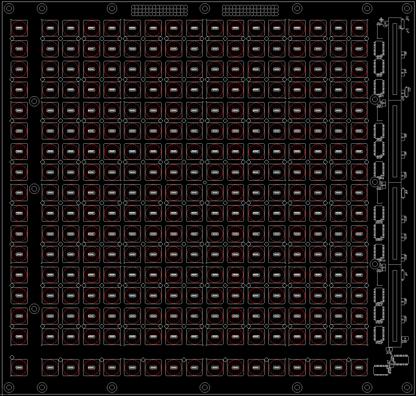
I’ve spent quite a bit of time in designing a full 16x16+X BLM.
It’s using the ADAfruit silicone pads and rear-mount LEDs.
First I tested the LED concept with OSHpark boards. I tried red, green (not yellowy green), yellow and blue, and all of their combinations for the “third colour.†Although I was happy with the illumination for red and green separately, their mixing is unfortunately quite poor. What does work however is red+blue = pink and green + blue = cyan/white. The latter is my pick to use in BLMs. Yellow LEDs looked okay but only the combination with red was decent, albeit not very different in colour.


I have a 300 mm wide 4-layer PCB made up that additionally incorporates all 5 SCALAR modules and 4 sliders for analogue action. The sliders are Bourns PTL meaning there’s one LED in each too! Not just for bling, these are some of the lowest profile available. One concern I have is that the SC trace changes layer quite often (clock is best when it doesn’t go through vias), although I’ve routed everything in a chain like TK suggests. If you have any experience with this, please share! But if the MBHP_DOUT and past standalone SCALAR boards work with their routing, then potentially this should too.
I kept one layer as a ground plane but used each of the other three for routing. Too hard with all of the cutouts and the top layer predominately un-masked copper. Current sinks are BC818 transistors (SOT23), shift registers are SOIC16, and resistor arrays are a wider version of this. LEDs are approximately 1206 size. I have through-hole 1N4148 diodes which will need to be trimmed short and soldered from the rear. Also there are leaded 100nF decoupling caps, which is again not best design practice but I can change them if anyone objects. I figure that you have to place a via in any case… I put in 0604 RC termination footprints in case this is necessary.


The costs are reasonably high. I calculate a finished unit might be as much as $800, with the machined case being around $350 and a $250 Mouser order, mostly for LEDs. The button pads, PCB and spacer make up the rest.
So… my question is: who would like to build one? It would be really helpful if you could indicate by replying below. The more interest, the cheaper it will be for everyone. Of course I will get one unit working before going further. It’s just good at this stage to test the water.
-
Hey,
What's the motivation for this one? The original is 80x80 mm so your's isn't that much smaller. Do you have a particular space constraint? I don't use Altium so I can't comment on the PCB design, but I'd suggest:
* Through-hole electrolytic caps. SMD are a pain in the butt, perhaps better with a reflow oven but I'm dubious about DIY versions of these in terms of their temperature homogeneity. The trimmers also look like they'll be annoying to mount, and are less mechanically robust for the long term.
* 2x5 DIL header for data. The original pinout is also incompatible with modern Cores.
* Better clearance around mount holes.
* Consideration of a new offset circuit that is truly switchable. Check some of my posts or Altitude's MAX525 SMT design.
-
I have a linear, bipolar, regulated ±15V PSU, but I have an AOUT_LC, not NG. Does it work with 15V, too?
The LC uses a TL072, fine to run this on +/- 15V. The only change would be to adjust R50 and R52 to make the offset trimming easier, but maybe it's fine as-is. Try it!
-
It's not clear what you have. When you say "a complete PSU instead of a transformer on its input" does this mean you have a 15 V plug pack of some sort? If so is it AC or DC? I think if you try to wire a 7812 and a 7912 in parallel you will have problems.
Or if you've already got a regulated bipolar +/- 15 V PSU then that's fine to use for AOUT_NG without modification. Is it linear or switching? Linear will be better.
Some more info or pictures will help to get the best advice for you.
-
Did you want to build your own BLM PCB (either fabbed or on Veroboard)?
If so, it's more than possible but involves some work:
http://www.ucapps.de/mbhp/button_duoled_matrix.pdf
http://www.midibox.org/midibox_seq_blm_ext/
But if you have the PCB already, you have everything you need to make it work, the SRIO chain is onboard via SMDs.
-
 1
1
-

CV / Gate clarification help
in MIDIbox SEQ
Posted
Hello, you should configure your track as AOUT channel 1, this should send the gate. It would be great if TK could tweak the SW to allow all 16 channels to send their gates to the DOUT, I think with the BLM this will be really cool even if the corresponding CV is not sent.