

latigid on
-
Posts
2,524 -
Joined
-
Last visited
-
Days Won
149
Content Type
Profiles
Forums
Blogs
Gallery
Posts posted by latigid on
-
-
I too, received no PM with the invoice. Only the one on the 2nd of August.
Hello, you requested bank transfer as payment method, I haven't sent these yet as I am setting up a USD account (no point in exchanging currency twice...), plus a few people don't have the funds to pay at the moment.
Here's the current situation: I have had 7 payments already from PayPal, one which I would re-send and 5 to be paid by bank transfer. I calculated pricing for 16 cases, and as three people have pulled out for now it puts me behind. I've contacted all the others who expressed interest in the project asking if they want to join.
I see these options:
1) Hopefully get enough signed up to make the quantities (perhaps I'll wait one week for answers)
2) Order at the same price with the hope/expectation that others will come in later. I may need to take a small deposit from the "waitlisted people" if that was the case.
3) Hold the payments now and wait for more people to join.
4) Go ahead with the order, but with increased pricing for the cases given the lower quantities.
5) Refund just the case costs, have a new order open for cases.
6) Refund everything, wait for more sign ups.
7) Flag the whole idea for now.
To anyone that has sent me money already, I'm sorry about this situation and I'm doing my best to fix it. Also learning internet Bulk Orders as I go :smile:. I'm not out to screw anyone, and if things are looking down I will refund your payment straight away. Let's discuss via PM if you need anything clarified.
When the best option is clear I will send out invoices for bank payments.
-
 1
1
-
-
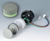
Another option is finding hollow shaft encoders and sticking a normal through hole RGB LED in.
-
I was sure I did, but you're right, I'm sorry. Internet is being a bit funny here today.
-
I cancelled your one and somebody else's as explained by PM. I have no margin on the cases as I figured you'd want them as cheap as they could be. I have contacted all of those who expressed interest in the hopes of maintaining the same pricing. But I'm not going to risk a personal loss, even though I could order some cases now and some later at the same price. I have to commit to a certain number, and I realise now that circumstances change and no one can guarantee that they'll have the funds in a few months, which could leave me thousands out of pocket. If I can't get the numbers I will have to increase the pricing or refund those already paid.
Sorry for the inconvenience to all involved... but it won't be a problem if I can just get a few more on board. I'm hopeful of this :)
-
Hello,
Hmm, sorry about your circumstances. I have to see if there's sufficient interest from the waitlist, otherwise I might have to refund the already collected PayPal payments or adjust the pricing. It might be an option to just order the PCBs for now and do a run of cases later.
-
Just thinking about this a bit more, RGB encoders are known (and by the way: supported by MIOS DOUT to 7 levels + off, so no I2C buss/chips needed), but perhaps a bit too expensive. To make matters worse, it looks like a lot of them are common anode *facepalm*.
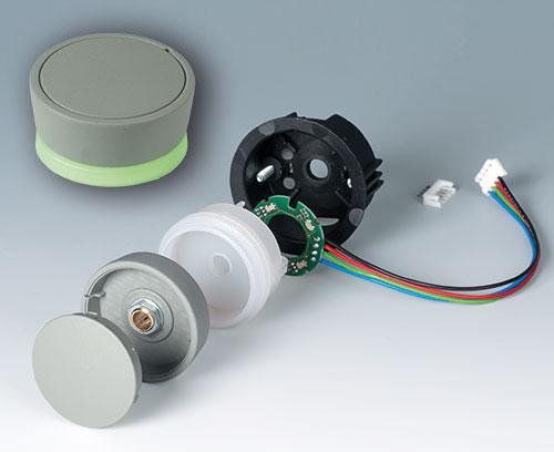
Another idea is to find a way of making a "collar" that sits over the shaft with the knob on top. On the PCB side a few RGB LEDs would illuminate this "lightpipe". So it could work out a bit cheaper and more flexible this way.
See this "Star Knob", a bit big, but the concept is about right.
-
Hello,
I have sent out the PayPal invoices, many thanks for those that have paid already. I just have to make the PCB gerbers and they'll be on the way.
I figured it would be best to open a USD account to make things easier, so I will get that set up and send out bank payment details early next week.
Just a note on the cases: I realise that $270 seems expensive, so I thought it might be interesting to see what it would cost at FPE.
A 330x330 mm square panel in 3 mm aluminium with the 289 holes, 5 M2 threaded holes, slots and milling for the sliders, and 20 M3 blind studs comes to a single price of $322.03 (with discounts depending on quantity). Remember that the case I specified includes bends which really helps with the stability, cutouts for the DIN connector, the second U-shape piece with rubber feet, powdercoating for longevity and worldwide shipping (with luck VAT free).
The pricing is also based on the quantities requested so far, which I'm basically ordering at cost. I'd say "trust me" and pick up a case with this bulk order as I probably won't be able to offer this pricing again unless there was similar interest. I could try to anticipate the total numbers, but this would be at my own risk. Worst case I would take the extras and possibly build them for sale or offer them in kit form for latecomers, but here you would lose the free shipping option.
Anyway, it's of course up to you whether you want a case or not (most people have). I also need to enlist a few more sign ups as a few have asked to move to the waitlist.
-
Hello, welcome to the forum! That shouldn't be a problem, just leave J17 open/not jumpered.
-
-
You do know that the BLM you're going to get has 4 sliders and 4 available AINs right ? :smile: It's pretty good really, as the 8 bit Core gets a good workout this way. At the moment they can't be selected in the "External Control" section, but I bet TK will add this soon enough.
Another option would be to go down the MBCV path and convert some CVs to CCs, then use a second MIDI in for control. EDIT, sorry, this was mentioned just above...
-
Dear all, many thanks for the PM responses so far. I am currently waiting on info from
grizz,ganchan, blingy, and sonicwarrior. The PCBs are basically finalised, I will order the batch and build another, then commit to buying cases. If I can get payments reasonably quickly you might get your boards in 4-6 weeks or so. -
I've spent a few days scratching my head with the BLM. Basically when applying power the Core boots up fine but the LEDs are lit up, sometimes all, sometimes in random patterns. I have a Meanwell 2.5A SPSU supplying 5V to both the Core and the BLM+miniCore.
What I imagine happens is the SRs have undefined states on startup which leads to a kind of latch-up condition. If I reset the power once the miniCore and 5V are stable, the communication initialises as expected. Having a hard reset button is a bit too brute force, so I've arrived at a solution which works every time. I essentially cut the 5V line and implemented a low pass filter with a 0.68R resistor (cap is 470 uF). This does draw a bit of current, but suppresses the initial spike and there is little to no loss in brightness. The LPF is after the miniCore's power, which always initialises first.
It's possibly peculiar/particular to my PSU, I'd love to scope the start up but I don't have a DSS... Linear supplies with good regulation will probably have no trouble. I thought CMOS chips normally had a power-on reset, but it seems like the combination set up in the BLM (current surge? long chains?) can produce some strange results.
Perhaps another method would be to control the /OE pins of each shift register, but I can't think of a neat way of doing that without tying up 24 MCU pins or having horrible fly wires everywhere.
So, more of an FYI as I have a solution already, but of course any insight or experiences are welcome.
-
Is the pricing in the OP still correct?
Cases are $270 due to the modifications mentioned. Postage a little cheaper. 18 button pads are $79 from Mouser.
So your location is Switzerland? Because that would mean the involvement of the customs office.I will post when next travelling to the EU for cheaper shipping, unless you prefer otherwise :)
-
Okay, I've sent out PMs to request addresses etc. I'm looking to get the PCB finalised, then I will start to request payments.
Best,
Andy
-
1
-
-
Sweet! That's about the same size as the BLM, would make a good couple on the MIDIbox battledeck!
Well done,
-
Another point: Mouser have gotten back to me about the button pads. While they are listed as "non-stocked", apparently the delivery time is 1-2 weeks. The pricing is fair, but there will only be about $10 difference in a larger bulk order, so it's easier for everyone to just get theirs directly. This is a great way to get almost everything in one order, especially for Europeans who will even get free shipping.
-
Okay, case revs are final then. :)
I've made several improvements which will bump the price up slightly, these include 6 extra studs and 4 threaded holes to secure the front panel, the latter M2 grub screws are optional. Everything is nicely symmetrical and even functions as a visual guide. Also my idea of mounting the rubber feet through the bottom nuts didn't work because the actual screw threads are too short to get past 3.2 mm aluminium and into the integral nut. So there are 4 more there and these are the reasons for extra cost.
I think you'll be very happy with the cases though, they're sturdy and stylish.
-
Interesting, it looks like Mouser will soon stock the button pads. If so, that's a great way to get almost everything in one order. I'm a bit busy but I'll try to get PMs out in the next few days to confirm addresses, payment details etc.
Mouser part:
485-1611
Currently out of stock but I've requested a delivery quote.
-
Another good one! Very picturesque at the end there.
-
Thanks!
Maybe it's weird lighting, but this BLM has three colours: blue, green and cyan (and off). The way I've wired the LEDs would correspond to TK's green, red and yellow. You could also choose to swap the green with red, then you get pink as the third colour.
-
Looking good!
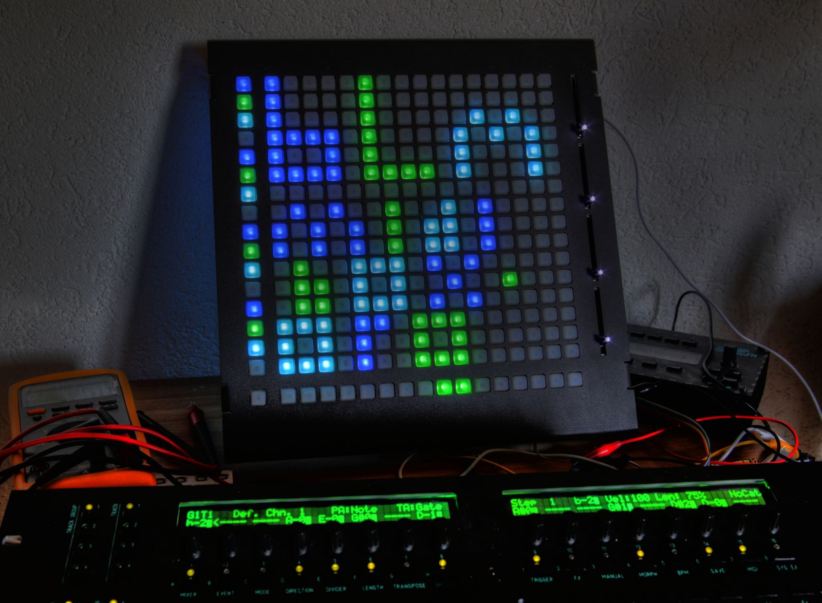
Lamouette asked if the illumination is okay in sunlight. I shone a 10 W fluoro lamp on and you can still make out the colours although it's much better when it's a bit darker. In any case I'm happy with the brightness.
-
Bonus: you could use the holes as sockets for CV inputs to control the SEQ. :smile:
Would need to implement a diode protection circuit, but there are two a "muck" areas onboard.
-
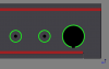
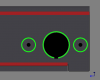
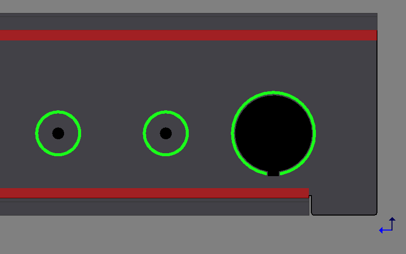
Here the hole centres are 25 mm apart, same 10 mm diameter indicated in green.
-
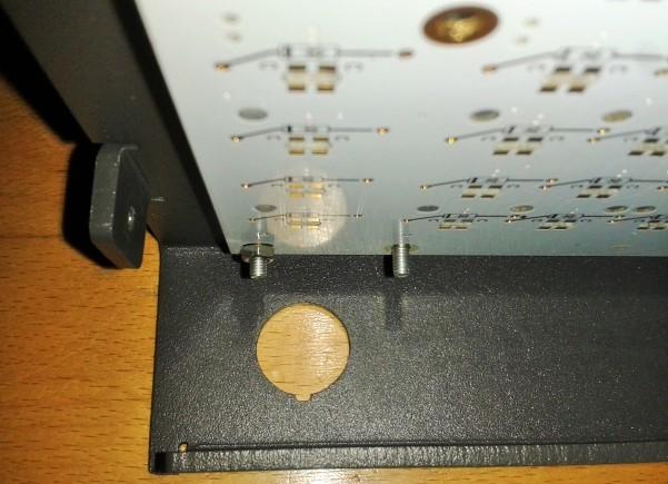
Can I request that the polit holes have their centre in line with the centre of the larger hole (which I guess is for the DIN connector) on the vertical plane?
This shows the internals, I don't think it's possible to fit both in a vertical line.
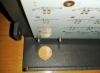
Horizontal I can do, the green outlines are 10 mm. But of course it's nicer to have all the cables out of the way on one side.

BLM 16x16+X PCB and case order [CLOSED/waitlist]
in Bulk Orders
Posted
I am hopeful, let's wait one week to see who gets in touch with me.
For the parts list I have the Mouser carts ready to go (you can then try to find alternative parts if you want) but as they normally ship within a day or two I think I would rather check the final PCB version first.