rvlt
-
Posts
164 -
Joined
-
Last visited
-
Days Won
3
Content Type
Profiles
Forums
Blogs
Gallery
Everything posted by rvlt
-
Hi Peter, yes, I guess you're absolutely right, since I just started programming, and this would be more than copy/paste a few lines... To get the project started I just bought a TDA1543 on ebay yesterday, but it will arrive at my place in "20-30 business days" .. dooh. BTW, a killer feature would be a loop mode for longer samples (to play sustained notes, chords, pads, organs...). right now it's more like a Mellotron ("samples" stop after a few seconds), but this could also be nice. Maybe I make a MIni-Mellotron .. ;)
-
Hey, just wondering: would it be (theoretically) possible to merge this player with another application, e.g. the new MidiBox KB? I have an old Solton Keyboard I want to "midibox", and having this player would make it a nice little sample keyboard. Would be great if this would only use one LPC17, but don't know it this would work at all... I guess polyphony could suffer. cheers, Lars
-
Ah ok, I see. Unfortunately the 7219 are all SMD, but for me still easier to desolder and put 7221 in than learning assembler ;) Reichelt has them in stock, so I think I'll go this route. About the DIN/DOUT: is this really necessary to create a chain? I'm just asking because Tascam didn't use the DOUTs at all on their PCB. The datasheet says the signal at DIN is the same at DOUT, only "16.5 cycles later." Don't know if this is important for your driver. Leaving the DINs like they are now would save from cutting a few PCB traces. But still doable though.. Thanks for your help Lars
-
Wow, thanks! Now it works, I mean on/off & multiple leds. The only thing left is addressing the different chips individually, right now the leds on all three 7219 light up at the same time. When I use a different stribe number via STRIBE_SetLED(...) , only some other leds are addressed on the same 7219, but not a different 7219. I guess i that could be either.. - because compared to the stribe project i have 7219s and not 7221 ? (Is there a difference between LOAD/CS?) - on my tascam pcb the DIN on all 7219 are connected together rather than a DIN > DOUT chain from one chip to another - I have a PIC18F4620 and no PIC18f452 installed right now (I could change that..) I could give more details later, but have to work now. Gotta hurry.... Thanks TK !
-
Hello, some more questions about the MAX72xx driver, this time on MIOS8 with a PIC-Core. ** First of all I must say that I'm a totally newbie when it comes to programming. I've managed to get my Tascam up and running (buttons and button matrix, some single leds..), but addressing LEDs with the MAX-driver is way over my head.** So, what I'm basicially looking for is a simply way to turn LEDs on and off via note on/off events. If I want to control LEDs directly connected to DOUTs I use the "MIOS_DOUT_PinSet" function. Is there some kind of equivalent in the MAX72xx driver? I messed around with the stribe project a bit, and I guess the "STRIBE_SetDot" function is what I'm looking for, but there are some problems: a) there is only one LED at a time lit, as soon as I press another note the first LEDs turns off, and b) there are three MAX7219, and I don't know how to address each chip separately. So before digging around in the stribe code too much, is there a simple way to use LEDs via MAX7219s by just using the driver (without any stribe stuff)? Best regards Lars
-
Midibox and 9090 Drum Individual Accent... is there a Way to realise this
rvlt replied to jamie's topic in MIDIbox SEQ
This sounds brilliant!! If it's not too much hassle: could you tell us the dimensions (approx.) of the PCB? Thanks, Lars -
Midibox and 9090 Drum Individual Accent... is there a Way to realise this
rvlt replied to jamie's topic in MIDIbox SEQ
Wow! Just to get this right: This board shown above together with a Pic-Core will give me a standalone drum sequencer, right? Or is the Pic-Core circuit already integrated on the backside? Best regards, Lars -
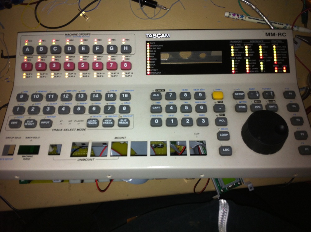
Hey, is there a way / a driver to access a MAX72xx under MIOS32? I know there is a MAX72xx driver in the svn in the MIOS8 path, but none for MIOS32. The reason I'm asking is that I have a midibox'ed Tascam MMRC (with a few MAX7219), and i'd like to put a LPC17 (USB, Ethernet..) in there instead of my Pic Core. Best regards Lars
-
Hey, I built my small "Ainser8" on breadboard today and it all works perfectly! At first I wondered why a single pot would send 8 values at a time, but then I figured out that I had to disable all the pins which were on by default. btw I bought my MCP3208 from Segor, and they have two different versions (C and B, which has slightly better specs) of the chip. In the store I was unsure what to buy so I just got the B version to be on the safe side, but maybe that's not necessary at all. anyway, no more jitter! Thanks!
-
Ah, sure ... I thought it way too complicated. Thanks, you just saved me a lot of work. Will report back when I finished the breadboard. Cheers!
-
Nice!!! I'll try that as soon as I finish my small "ainser8" board Thanks TK !!
-
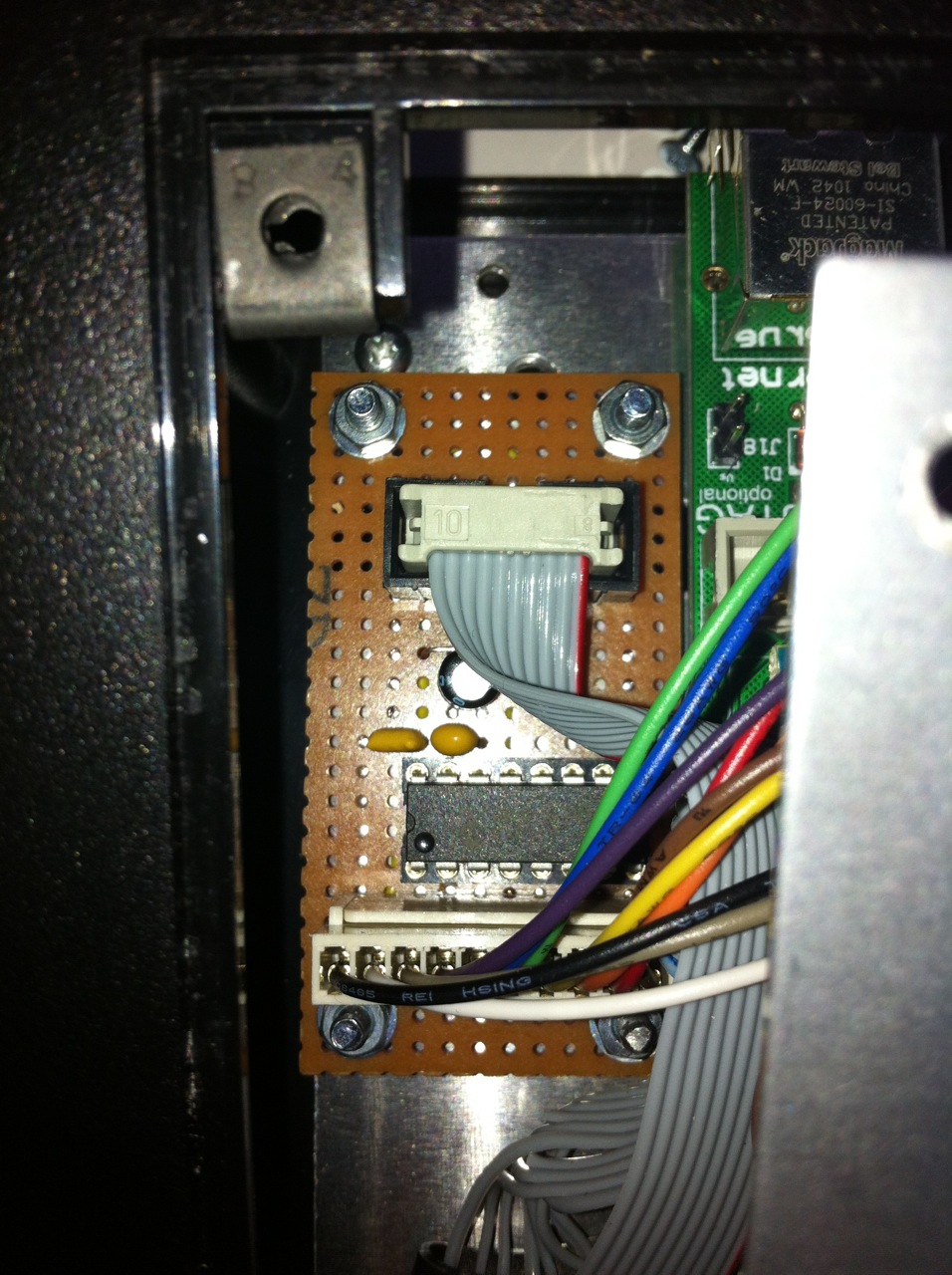
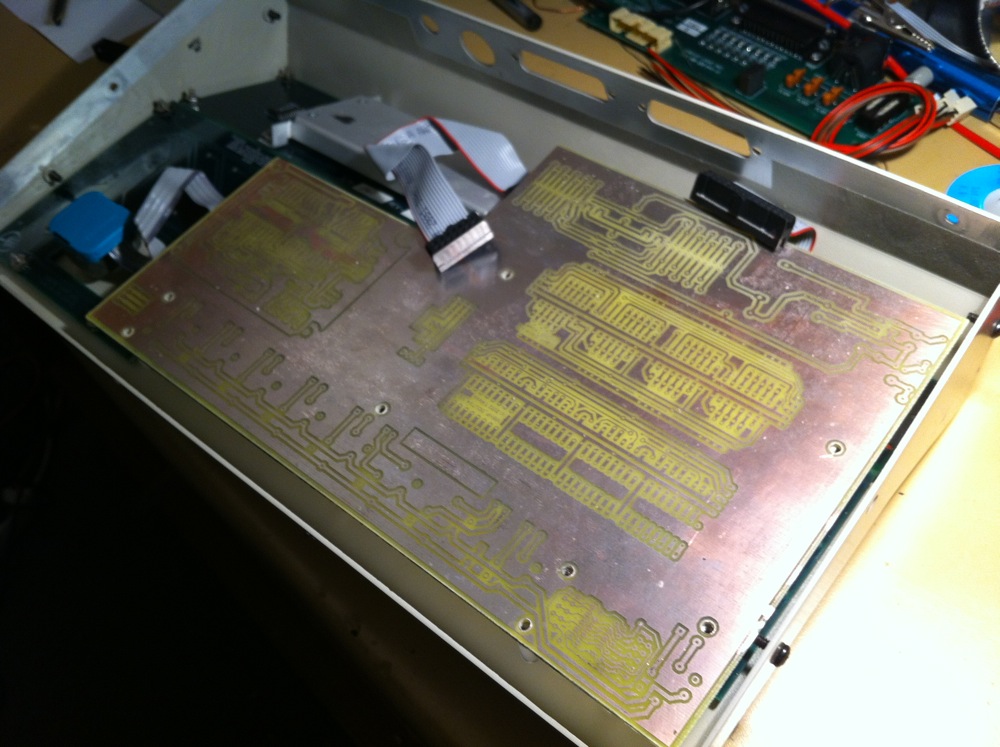
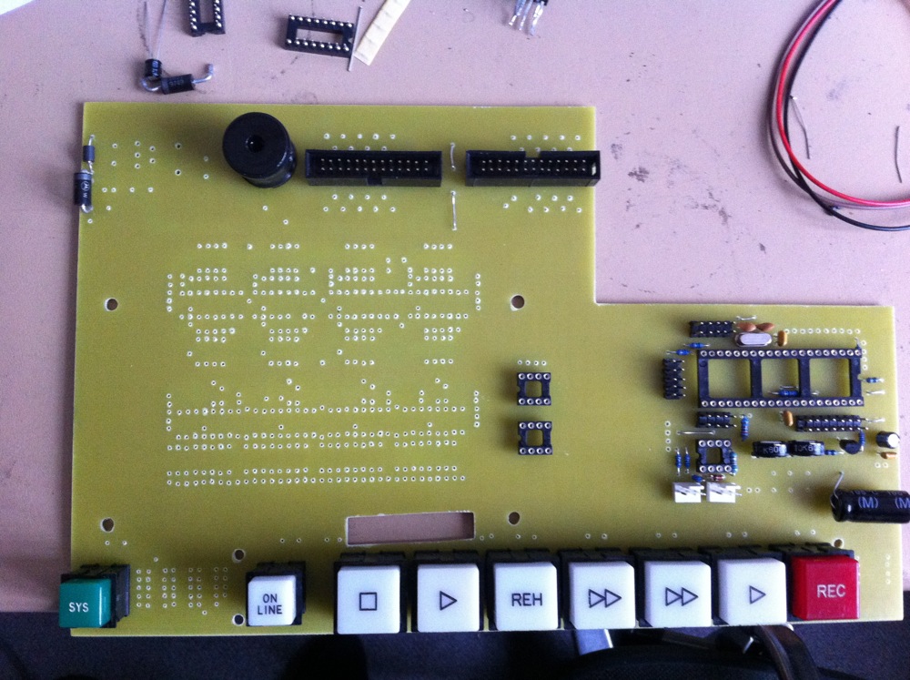
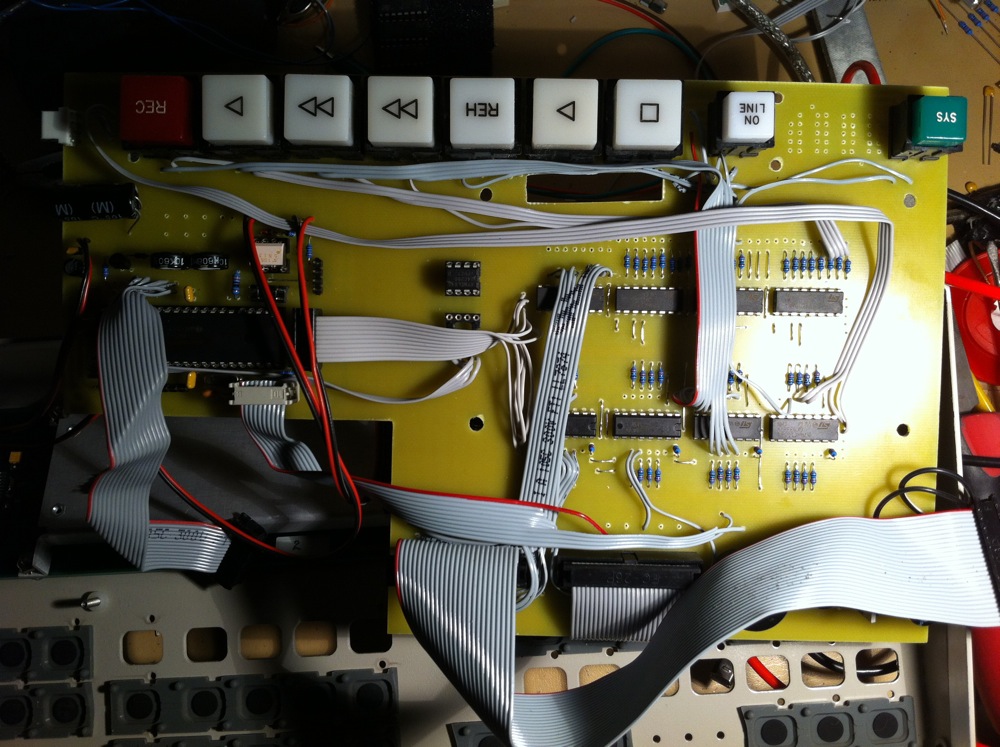
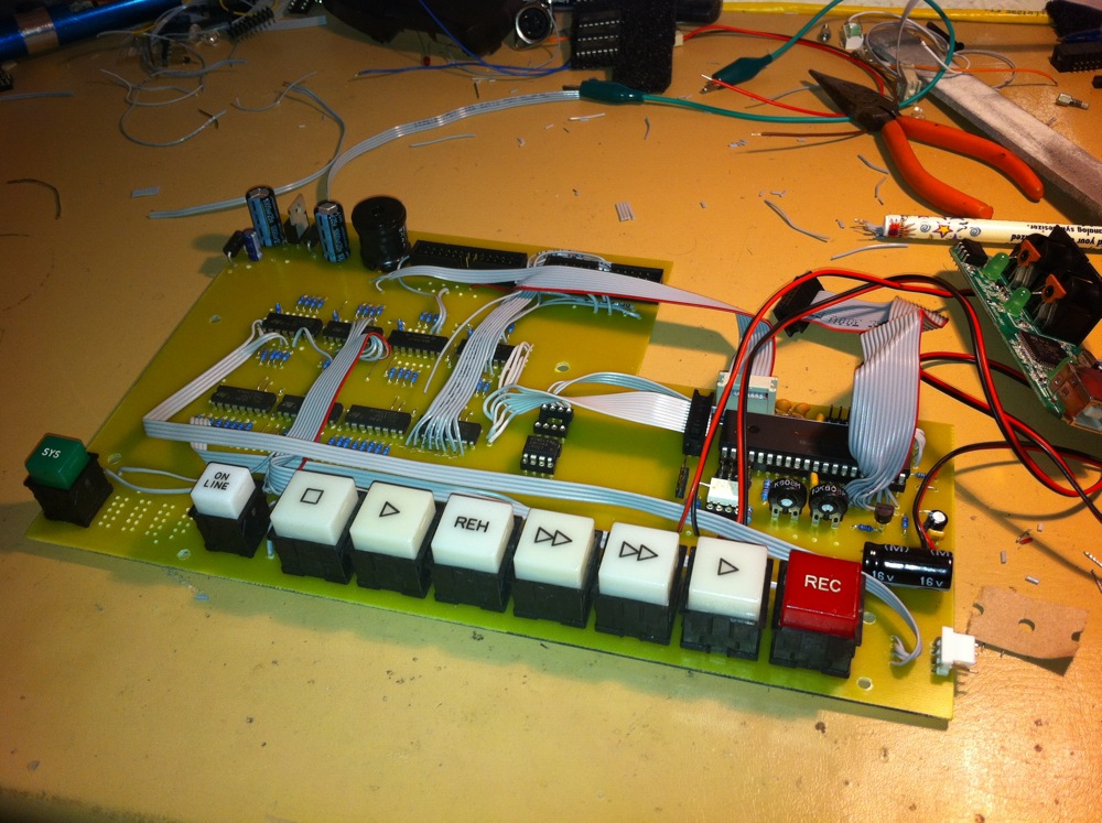
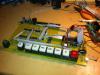
Some progress with my Tascam project: I replaced the main pcb with a self etched one. I didn't want to do it from scratch, so I just took the already existing designs, put them all on the board and connected them via ribbon cables. This also gave me the chance to try different connections easily. - Core8 - DINX4 - DOUTX4 - Bankstick 2x - PSU Section from original board - 2x ribbon cable connectors for the two control surface boards I also put a Midisport 1x1 USB interface in there. So I did a few tests: I uploaded - MIDIO128 for big buttons (connected directly to DIN/DOUT) and the encoder (works) - scan matrix example (works with the lower buttons) - stribe project (leds light up). so far so good. On the hardware-side I only have to put the 7segment leds onto the pcb. As a programming newbie I still have to find out how to put all these functions into one program. And how to make the scan matrix work with more than 8x8... ===== Uups?!? i can suddenly see all of Narwahl's photos, for the first time!! maybe it's because I've added new pics to this threat? anyway, great!


-
Hey, I did a small PCB layout for a "ainser8" with only one 4051, since I only need 8 analog ins. Haven't etched it yet, but will do in the next few days... I connected CH0 of the MCP3208 to Pin 3 of the 4051, and CH1-7 to ground. Then I noticed in the AINSER64 schematic that CH0 is actually connected to the last one of the 4051s (IC11 / J13), not the first one. Does this matter at all? Or is it better to use CH7 with a single 4051 setup?
-
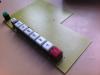
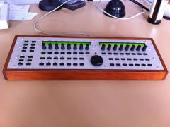
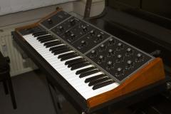
From the album: rvlt's MB stuff
-
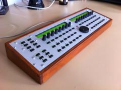
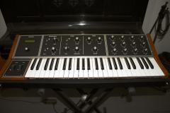
From the album: rvlt's MB stuff
-
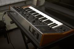
From the album: rvlt's MB stuff
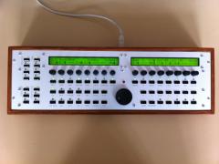
My MB Seq V4 I finished last summer. Front panel is from www.thebeast.co.uk and looks pretty nice. still haven't finished the back panel. On the inside is a core32, a mb seq pcb, sd-card and a self etched "2x IIC Midi + MB-Eth". Sorry, got no inside shots at the moment. -
From the album: rvlt's MB stuff
-
From the album: rvlt's MB stuff
-
From the album: rvlt's MB stuff
-
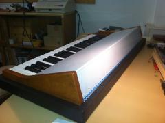
From the album: rvlt's MB stuff
finished! -
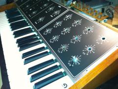
From the album: rvlt's MB stuff
attaching stickers -
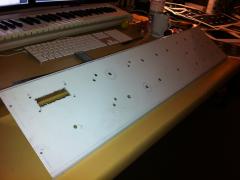
From the album: rvlt's MB stuff
drilling the front panel -
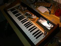
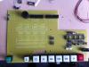
From the album: rvlt's MB stuff
some internals: the PSU on the right is from an old EMU Esi32, in the middle the main pcb form a old miditech keyboard, and far left is a Core8 + DINX2 + Bankstick -
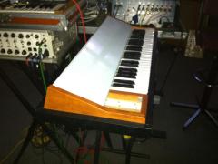
From the album: rvlt's MB stuff
checking with the rest of the live setup -
From the album: rvlt's MB stuff
... and painted